Page is loading ...

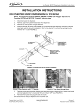
Kit Numbers: KDIL-N-CFF
Kit Purpose: To lower the ice level in the Cornelius Flavor Fusion or IDC255 ice
dispensers when a Scotsman Nugget ice machine is stacked on top of the dispenser.
Kit Contents:
Bin
thermostat
Baffle/cap tube
bracket, grommets
& fasteners
Switch body
mounting
bracket A
Switch body
mounting
bracket B
Wire
KDIL-N-CFF 11-0353-23 included
For NME454,
NME654 or
NME954
For NME1254 included
Applications & Other Requirements:
• NME454, NME654 or NME954 - requires Cornelius adapter
• NME1254 - requires Cornelius adapter
Installation Sequence:
1. Ice slide - included with Cornelius adapter.
2. Adapter. Note: Retrofits of existing ice machine stacked on the dispenser will require
a new adapter.
3. Ice machine.
4. Thermostat kit.
Pre-Installation check list:
• Removal of old ice machine and adapter (when used)
• Dispenser and adapter are properly installed.
• Ice machine is placed onto dispenser / adapter combo.
1
Instructions

Installation: Dispenser
1. Disconnect electrical power from both the ice machine and the dispenser.
2. Install ice slide per the instructions provided with the adapter.
3. Install adapter per its instructions.
4. Place nugget ice machine onto adapter. Be sure to seal the ice machine to the
adapter. Note: sealant supplied with adapter.
Ice Machine
5. Remove front panel.
6. Remove control box cover.
7. Uncoil the bin thermostat capillary tube.
8. Route the cap tube through a nearby snap bushing in the control box.
Note: Refer to table below to select thermostat mounting and cap tube routing
method.
NME654 and
NME954 without
routing hole
NME654 and
NME954 with
routing hole
NME1254 without
routing hole
NME1254 with
routing hole
Thermostat switch
body mounting
Mount to supplied
bracket A
Mount to supplied
bracket A
Use supplied
bracket B
Use supplied
bracket B
Cap tube routing Route next to chute
Route through hole
in base
Route next to chute
Route through hole
in base
9. Mount the thermostat inside the control box to the supplied bracket. Use the proper
bracket from the kit.
2
Electrical Shock Hazard
Disconnect electrical
power before beginning

A. Remove lowest mounting screw from the back of the control box.
B. Place the thermostat and bracket in the control box as shown in figure A or B. Attach
to the control box with the screw previously removed. 9. Connect the wire from the kit to
one terminal of the bin thermostat.
10. Disconnect top wire from toggle switch.
11. Connect wire removed in step 10 to open terminal on bin thermostat.
12. Connect wire from bin thermostat to open terminal on toggle switch.
13. Route bin thermostat capillary tube through foam gasket next to ice chute or through
hole in base if available.
3
Figure A, Using Bracket A (for NME654 or NME954)
Bracket
attachment
here
Toggle
Switch
Wire
From Kit
Bracket A
Note: Bracket A is
long and thin.

4
Figure B, using Bracket B (for NME1254)
Cap Tube Routed Next to Ice Chute
Bin
Thermostat
Capillary
Tube
Bracket B
Route Cap
Tube Thru
This Snap
Bushing
Note: Bracket B is
short and wide.

Dispenser Adapter and Cap Tube Mounting Bracket
14. Insert the three grommets from the kit in three holes in the cap tube mounting
bracket, two at bottom and one in upper hole as shown.
15. Route the bin thermostat cap tube from the ice side through the first hole, then from
the other side through the second hole.
16. Route the cap tube from the second hole to the third. The loop between the 2nd and
3rd holes will face the ice.
18. Form a loop on the inside of the bracket about 1" away from the bracket at the
center
5
Ice Side View
Bracket
Grommet
Cap Tube
From Bottom of
Ice Machine
2nd Hole
1st Hole
Cap Tube
Loop
3rd Hole

The bin thermostat's contacts are now in series with the mode switch of the ice
machine. The bin full light on the ice machine control board will not react to the
thermostat. The thermostat will stop the ice machine when the ice touches the capillary
tube. It will restart a few moments after ice is no longer on the sensor.
19. Attach the bracket to the adapter using
the hardware from the thermostat kit. The
bracket with cap tube slips under the
adapter, the two brackets when bolted
together form a clamp to secure the
bracket assembly to the adapter.
20. Be sure cap tube is routed away from
the ice being discharged.
Dispenser:
21. Set the dispenser agitation for 2 seconds on, 3 hours off.
22. Reconnect electrical power.
23. Return all panels and covers to their normal positions and secure with the original
screws.
17-3136-01
6
Position Cap Tube Mounting
Bracket 12" on center from left of
the dispenser cabinet
Secure Cap Tube Mounting
Bracket to Adapter Flange
/