Page is loading ...

IMI CORNELIUS INC. 2004
March 2, 2004
630460064INS
1 Rev A
IMI CORNELIUS INC g One Cornelius Place g Anoka, MN 55303-6234
Telephone (800) 238-3600 Facsimile (800) 535-4321
INSTALLATION INSTRUCTIONS, BIN STAT KIT, P/N 630000408
These Bin Stat kits apply to all “I” Series Ice makers
Table 1. Loose–Shipped Parts
Item No. Part No. Name Qty.
1 630900413 Spacer, Hex 5/8” Long x 8–32 SS 1
2 70894 Screw MA 08–32 TRPH 24 SS 1
3 51348 Spacer 1
4 630000413 Thermostat Asy 1
5 620037008 Bin Stat Support 1
6 630460064INS Installation Instruction, Thermostat 1
7 168833002 Washer SR 4W SS E#8 1
1. Disconnect power.
2. Remove front cover of the unit and the electrical box cover plate.
3. Carefully insert the coiled capillary tube through the bottom hole in the electrical box where the elec-
trical wires are coming through (see Figure 4).
4. If there is not a hole already in the chassis base, drill a ½” hole in the chassis base as indicated in
Figure 3.
5. Straighten approximately 12” of cap tube to go through hole. Re–coil the remainder. Do not disturb
coiled end.
6. Insert the “1/4” diameter wire form support into the coiled end of capillary tube and insert the assem-
bly through the hole in the chassis base. Route capillary tube to follow support as closely as pos-
sible.
7. Remove the 8–32 nut (closest to the ½” DIA hole) that holds the compartment wall to the base. The
adapter kits that have a single level, adapter kits P/N’s 02390, 630200153, 08006, 02388, 08004,
630000191 and 08010) require a 7/8” high spacer be used to mount the binstat support. Thread the
8–32 x 5/8” hex spacer on to the compartment stud. Then fasten the thermostat support to the hex
spacer using the ¼” high plastic spacer, #8 flat washer and 8–32 x ¾” long phil. head screw. The
spacers are not to be used on the elevated adapter kits. Refer to Figure 2.
8. Any excess capillary tubing must be pulled back into the compressor compartment to prevent ice
from damaging it during dispenser operation.
9. Seal ½” diameter hole with sealant (RTV).

IMI CORNELIUS INC. 2004
March 2, 2004
630460064INS
2 Rev A
10. To mount bin thermostat in electrical box:
A. Clean the mounting area by rubbing briskly with Scotch Brite pad (see Figure 4 for location).
B. Wipe down the cleaned area with rubbing alcohol and let dry.
C. Pull paper strip off of double sided tape on thermostat mounting bracket.
D. Being sure that bin thermostat is facing the correct direction, (see Figure 4) affix the thermostat
in the electrical box. Press firmly down on the mounting bracket to bound the tape.
11. Connect the bin thermostat lead to the circuit board (see Figure 1).
12. Turn bin stat adjustment screw clockwise until it stops. Then turn it counterclockwise 1/8 of a turn.
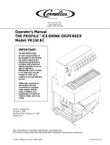
13. Reinstall the front cover of the electrical box and the ice machine and reconnect the power. Verify
that the Bin Stat is working by holding ice on the coiled bare capillary tube. The bin stat will allow the
ice machine cycle to complete and harvest ice. Then the ice machine will shut down. Remove the ice
from the capillary tube and warm the tube with hand heat. The ice machine should start in approxi-
mately 60 seconds.
Processor
Figure 1
SW4–2 ON
SW4–3 ON
BE CONNECTED TO J4 AND
6 CURTAIN SWITCH MUST
DUAL CURTAINS
SW4–1 OFF
J5,J6, OR J7.
ON OFF DUMP EVERY THIRD HARVEST
OFF ON DUMP EVERY SEVENTH HARVEST
ON ON FLAKER
OFF OFF DUMP EVERY HARVEST (FACTORY SETTING)
DUE TO UPGRADING OF CIRCUIT BOARD
NOTE LOCATION OF SENSORS AND WIRE
CONNECTIONS ON NEW BOARD.
FOLLOW SETTINGS #1–#4 FOR HARVEST SETTINGS.
FOLLOW SETTINGS #5–#7 FOR NUMBER OF CURTAINS.
36430001
(Manufacturing Date)
S3–2
Error
SINGLE CURTAIN
SW4–1 ON
SW4–2 ON
SW4–3 ON
5 CURTAIN SWITCH CONNECTED
TO ANY BIN CONNECTOR (J4–J7).
SW4
SW4
SW4
S3–2
S3–2
S3–2
Off
7
6
5
Off
1 2
On
1 2
3
3
Off
On
1
On
2 3
S3–1
S3–1
S3–1
4
3
2
Off
Off
On
Off
On
On
4
2
3
TOP TWO PINS OF STACKING
PLUG BIN THERMOSTAT ON
DUMP CYCLE
DIP SWITCH
DIP SWITCH
WATER CURTAIN
CABLE PLUG
S3–1 S3–2
1
Switches
Bin
Curtain
Switch
Selection
3
4
2
1
Com
Out
In
Stack
312
Off
YL
YL
YL
YL
Thickness
Bridge
Suction line
Sensor
pot.
Manual
S3–1
Harvest/Test
On
Micro
Off
Switch
On
RD
S3–2S3–11
Off
On
External Error
LED Connection
#6 BL Condenser Fan
BE CONNECTED TO J4,J5,J6, AND J7.
7 CURTAIN SWITCH MUST
SW4–1 OFF
SW4–2 OFF
SW4–3 OFF
FOUR CURTAINS
Comp.
Triac
GR
Transformer
Cond.
Valve
Dump
Water
Valve
GR
GR
Fan
Gas
Hot
GR
GR
Cond.
Triac
#2 RD L2
#1 BR L1
#3 RD Hot Gas
#7 YL Water Pump
#5 BL P.S.
#4 BL

IMI CORNELIUS INC. 2004
March 2, 2004
630460064INS
3 Rev A

IMI CORNELIUS INC. 2004
March 2, 2004
630460064INS
4 Rev A
1/4 SPACER
FIGURE 2
8–32 X 3/4 PHMS
5/8 SPACER
8–32 NUT (PART OF ICEMAKER)
WASHER
WASHER
620037008, BIN STAT SUPT
620037008, BIN STAT SUPT.
BIN STAT SUPT ASY FOR ALL
ELEVATED ADAPTOR LID KITS
CAPILLARY ASY
CAPILLARY TUBE
ICEMAKER E-BOX
ELEVATED
ADAPTOR KIT
SINGLE LEVEL
ADAPTOR KIT
COIL CAPILLARY TUBE
AROUND BIN STAT SUPT
8–32 STUD (PART OF ICEMAKER)
BIN STAT SUPT ASY FOR
SINGLE LEVEL ADAPTOR KIT NO:
02388, 08004,630000191, 02390,
630200153, 08006, & 08010

IMI CORNELIUS INC. 2004
March 2, 2004
630460064INS
5 Rev A
OF UNIT WITHOUT COVER.
* DIMENSION IS FROM FRONT
TOP VIEW OF 1230 CHASSIS PLATE
RIGHT HAND LINER
LEFT HAND LINER
ICE
DROP
ZONE
ICE
ZONE
DROP
DROP
ZONE
ICE
ZONE
DROP
ICE
4.25*
1.50
15.41
1/2” DRILL
ELECTRICAL BOX ASY
CLEAN MOUNTING AREA WITH
SCOTCH BRITE PAD,
THEN WIPE AREA DOWN WITH
RUBBING ALCOHOL AND LET DRY
THERMOSTAT KIT ASY
630000408
COIL
Figure 4
TO CHASSIS
PLATE
Figure 3
/