Page is loading ...

ZINST-EK1218072
ASSEMBLY INSTRUCTIONS
TO FULLY ENCLOSE 12’ X 20’ (ROOF) X 7’
2”SQ VERSATUBE CLASSIC CARPORT
WITH 8’ X 7’ GARAGE DOOR
PAGE 1
REV 2/11/13
Our unique assembly process quickly transforms the individual pieces into a finished
structure that will give you years of service. Great care has been taken to ensure
complete satisfaction with your purchase. In the unlikely event that there are any missing
or damaged parts or if you simply need technical assistance, please call our Toll Free Hot-
line at 1-800-900-7222 and your questions will be addressed promptly. Thank you for
choosing the VersaTube Building System.

SAFETY, HAZARD and MAINTENANCE INSTRUCTIONS
CAUTION:
Read the following safety warnings and all instructions in their entirety prior to installation. If you have questions or
are missing any parts, contact Mid-South Metal Products, Inc. (DBA, VersaTube Building systems) customer service
at 1-800-900-7222 before proceeding.
CAUTION:
VersaTube Building Systems designs and manufactures framing products to meet minimum load requirements in
most areas. It is the buyer’s sole responsibility to determine the specific building code requirements applicable in the
city and/or county of the state in which this product is being erected, and to ensure the product is installed with suffi-
cient materials and in such a manner as to comply with the codes.
WARNING:
Metal parts may get hot when exposed to high heat or direct sunlight. Avoid contact with skin and wear protective
gloves and clothing to prevent the possibility of burns.
WARNING:
Standing or walking on the structure could cause damage to the sheet metal panels. If you must walk on the roof,
step within 1’ of a major frame member. The structure must be properly braced to support human weight. Collapse of
the structure may cause serious injury do to weight of components.
WARNING:
Avoid installation on windy days as wind may create hazards during the installation process. Wind may blow material
or cause partially installed components to collapse prior to being secured or fully installed. The weight of the compo-
nents or structure may cause serious injury if it should collapse.
WARNING:
Metal conducts electricity and electrical shock hazards exist since the structure is made of metal. During installation
or storage, keep the structure and all components away from electrical sources. Make sure that your selected loca-
tion is away from power lines, underground cables, and any other source of
electrical power. Serious injury or even death may occur if contact is made with electrical current.
WARNING:
In the event that your structure is fully enclosed, be sure to provide proper and adequate ventilation and egress and
ingress. Hazardous, poisonous or noxious substances should not be stored in the structures absent proper ventila-
tion. Follow all warnings and instructions of the manufacturer of any substance stored in your building.
Also, proper ingress and egress should be provided to prevent persons or children from
Becoming trapped inside the structure.
WARNING:
If metal panels are selected to cover all or a portion of your structure, be careful of the sharp edges which may cause
cuts or lacerations. Wear protective work gloves and suitable clothing for protection and
always take care when handling metal parts.
NOTE:
The VersaTube Building System is an all domestically produced galvanized tubular steel framing system. Mainte-
nance is required twice annually on particular areas of the framing system i.e. ‘’weld seams” and “cut or raw ends”.
This maintenance is performed by applying any “Zinc coated” silver spray paint found at local mass merchant or paint
store to these areas twice annually or every six (6) months.
NOTE:
All sheet metal cladding applied to the VersaTube frame are attached with self drilling screws with a rubber washer.
These screws produce small shavings when drilling through the cladding. If the shavings are allowed to sit on the
sheet metal for an extended period, rust spots will form and promote deterioration. Metal shavings must be brushed
after installation of the sheet metal. Claims reported against rust spots will not be honored by VersaTube Building
Systems.
© MSMP INC. 2/13
PAGE 2

ATTENTION:
IT IS IMPORTANT THAT YOU READ THE FOLLOWING NOTES
BEFORE STARTING THE ASSEMBLY OF YOUR SHELTER
NOTE:
If you are not mounting the shelter to a
concrete pad, you should level the selected
area and remove high spots caused by roots
or rocks. It is particularly important that the
areas on which the shelter base plate
assemblies will sit are level with each other.
Choose a level site away from power lines.
NOTE:
If during the installation process you have
Difficulty fitting frame components together,
use an adjustable wrench to open end of re-
ceiving tube as shown at right.
Close wrench down around bent portion of
tube and bend wall outward.
What you’ll need:
Tape Measure
Hammer
Pencil/Marker
2 Step Ladders
Work Gloves
Level
Shove
Tin Snips
Cordless (14 or 18 volt)
Or Electric Drill
With 5/16" Socket Drive
PAGE 3

BACK ENCLOSURE FOR 12’ X 7’ HORIZONTALLY SHEETED GARAGE
PARTS LIST
PART NO. PARTS QTY. LETTER
71-BE-T T-SECTION 1 A
7400-5875 BASE RAIL 2” X 2” X 58 3/4” 2 B
74-8175 BACK VERTICAL 2” X 2” X 81 3/4” WITH SWAGED END 1 C
7400-1300 VERTICAL EXTENSION 2” X 2” X 13” 1 D
BK-10 ANGLE BRACKET 2 E
BK-20 FLAT BRACKET 1 F
71-9999-A 40 PIECE SCREW PACK, #12 X 1” SELF-DRILLING, HEX HEAD 1 G
ANC-24 GROUND ANCHOR 30” 1 H
SHEET METAL PANELS FOR BACK – 6'-1” (NOT SHOWN) 6 I
SHEET METAL PANELS FOR SIDES – 9'-2” (NOT SHOWN) 8 J
3”x3” CORNER TRIM 8‘, FOR CORNERS (NOT SHOWN) 2 K
SELF-DRILLING PAINTED SCREWS 250 M
PAGE 4
H
SELF-DRILLING
SCREW (G)
A
B
B
E
C
D
F
E
SELF-DRILLING
PAINTED SCREW
WITH SEALING
WASHER (M)

ASSEMBLY INSTRUCTIONS FOR BACK
ENCLOSURE FRAME BE-12-7.0 (12' WIDE)
STEP 1: BASE RAIL ASSEMBLY
Loosely assemble a base rail (B) on both ends of the T-Section (A). Place the loose base assembly on the ground or
concrete pad at the back of the building with the pin on the T-Section in the vertical position. Adjust the joint spacing
to be equal. The ends of the base rails should be touching the Side Base Rails of the building. Now fasten each joint
(from the top) with two #12 x 1” Self-Drilling Screws (G). (See Joint Detail)
STEP 2: ANCHORING THE BASE RAIL ASSEMBLY
Fasten the base rail ends to the building frame with Angle Brackets (E) and Self-Drilling Screws (G). Place the
brackets on the top of the base rails, one at each end.
Anchor the T-Section to the ground or concrete slab as you did the building frame with ground anchors (H) (provided)
or concrete wedge anchors (not provided).
STEP 3: ASSEMBLING BACK VERTICAL AND EXTENSION
Loosely assemble the Vertical Extension (D) onto the Back Vertical (C). Now, Place the Assembly onto the vertical
pin on the T-Section (A). Fasten the Vertical Extension (D) to the Peak of the building frame with a Flat Bracket (F)
And six Self-Drilling Screws G). (The top of the Vertical Extension should touch the bottom of the building peak. The
back vertical should be plumb. Now, fasten the joint of the Back Vertical and Vertical Extension with two Self-Drilling
Screws (G).
ANCHOR BOLT
(NOT INCLUDED)
1/2” x 7” CONCRETE
WEDGE ANCHOR
NOTE: Ground anchors can also
be set in concrete.
JOINT DETAIL
FLAT BRACKET
ASSEMBLY
DETAIL OF ANGLE BRACKET
PAGE 5
# 12 X 3/4” HEX HEAD
SELF-DRILLING SCREW
(G)
B
E
A
B
C
D
E
F

INSTALLATION OF SHEET METAL PANELS
NOTE: IF YOU PURCHASED A BACK ENCLOSURE, THE BACK ENCLOSURE PANELS MUST BE INSTALLED
FIRST.
INSTALLATION OF BACK ENCLOSURE SHEET METAL PANELS
STEP 1: CUTTING AND INSTALLING THE BOTTOM PANEL
Three 12' Sheet metal Panels (I) have been provided to enclose the back of the structure. You will be installing the
bottom panel first. Cut one of the panels to a width of 29 3/8". (measure down from the top/under lap edge of the
panel).
Place the panel on the back of the building at the bottom with the ends flush with the outside of the building frame
Side Posts. Lift the panel to leave 1/8" space between the bottom of the panel and the ground or concrete pad.
Make sure the building is square and fasten the panel to the frame corner and center posts with Painted Self-Drilling
Screws (with rubber washers) (M). Place screws 1" above and below each major rib. (See Rib Detail)
STEP 2: INSTALLING PANEL 2.
To install panel 2, lap the bottom (overlap) rib over the top (under lap) rib of the lower panel, flush the ends of the
panel with the outside of the building frame, and attach with screws as you did the first panel.
STEP: 3 CUTTING AND INSTALLING PANEL 3 (TOP PANEL)
Put the top panel in place on the building and (with a pencil or marker) trace the building roof contour on the back of
the panel. Take the panel down and cut the panel to fit. Return the panel to the building, flush the ends of the panel
with the outside of the building frame and fasten with screws (one at each end above the major rib, above and below
each major rib to the center post, and along the roof frame members as needed.
If you are installing the sheet metal panels after the roof has been installed, you will need to use the dimensions
below to cut the panels. You will also have to loosen or remove the end screws in the roof panels to insert Closure
strips (O) then reinstall or tighten the screws.
RIB DETAIL
FLANGE
OVERLAP RIB
BOTTOM OF
UPPER PANEL
UNDER LAP RIB
TOP OF LOWER PANEL
PAINTED
SELF-DRILLING
SCREWS
Bottom of panel 1/8” off the ground or concrete pad
PAGE 6
SCRAP
PANEL 1
PANEL 2
PANEL 3
12'
73”

FRONT ENCLOSURE FOR 12’ X 7’ HORIZONTALLY SHEETED GARAGE
ON A GARAGE THE FRONT ENCLOSURE IS ASSEMBLED TO THE FRONT FRAME SECTION.
PART NO. PART QTY. LETTER
HE-5 LONG HEADER TUBE 1 A
7100-3550 SHORT HEADER TUBE 1 B
7100-6775 DOOR VERTICAL TUBE 2 C
71-FE-L L-SECTION 2 D
7400-1300 FRONT BASE RAIL 2 E
BK-10 ANGLE BRACKET 4 F
BK-20 FLAT BRACKET 2 G
71-9999-A 40 PIECE SCREW PACK, #12 X 1” SELF-DRILLING 1 H
ANC-24 GROUND ANCHOR, 30” 2 I
SHEET METAL PANEL, 6’-1” (NOT SHOWN) 2 J
SHEET METAL PANEL, 2' (NOT SHOWN) 4 K
3”x3” CORNER TRIM 8‘, FOR CORNERS (NOT SHOWN) 2 M
SELF-DRILLING PAINTED SCREWS, WITH RUBBER WASHER 100 N
PAGE 7
SELF-DRILLING
SCREW
SELF-DRILLING
PAINTED SCREW
I
A
B
F
G
G
F
C
D
F
E
D
E
F C
P
PARTS LIST

ASSEMBLY INSTRUCTIONS FOR FRONT
ENCLOSURE FRAME FE-12-7.0 (12 WIDE)
STEP 1: Assemble Front base Rails and L-Sections
Assemble the Front Base Rails (E) to the L-Sections (D) Do not attach with screws at this time
.
Locate the Base Rail Assemblies as shown below and fasten the Front Base Rails (E) to the side Base Rails of the build-
ing with Angle Brackets (F) and Self-Drilling Screws. Place the Angle Brackets on top of the Front Base Rail. They should
line up with the vertical pin on the side base rail. Now, measure and adjust the L-Sections (E) so that the inside (door
opening) edges of the L-Section are 24” from the outside of the building frame and 8’ apart (door opening). Fasten the
joints from the top side with two Self-Drilling Screws per joint.
STEP 2: Anchoring the Front Base Rail Assembly
Note: The ground under the Front Base Rails must be level.
With the joints secure, square the assembles with the building sides and drive ground anchors through the holes in the L-
Sections into the ground or set the ground anchors in concrete. If Your building is on a concrete slab use 1/2” x 7” con-
crete wedge anchors (not included) to anchor the Base Rail Sections to the slab. (Refer to the bolt manufacturer’s in-
structions for proper installation of anchor bolts.)
HINT: You can use a carpenter’s square to square the Base Rail Sections with the building or snap a chalk line on the
ground from one front corner of the building to the other.
PAGE 8
#12 x 3/4"
Self-Drilling
Screw (H)
Anchor Hole
F
D
E
24"
DETAIL OF
L-SECTION
ASSEMBLY
GROUND
ANCHOR
(J)
CONCRETE WEDGE ANCHOR
1/2” X 7”
(NOT INCLUDED)

STEP 3: Assembling Door Verticals
Place one Door Vertical (C) on to one L-Section (D). Square the Door Vertical Tube With the building by measuring
and setting the distance from the outer edge of the building to the inside (door opening) edge of the door Vertical at
24" at the top. This should match the bottom dimension. Put a mark on the rafter above to use as a placement guide.
IMPORTANT: Make sure that your building frame is square before attaching the vertical door tube.
Attach the vertical Door Tube to the rafter with a Flat Bracket (H) and six Self-Drilling screws. The bracket should be
placed at the outside edge of the Vertical Door Tube. Mount the bracket on the inside of the building.
Now, secure the L-Section/Door Vertical joint with two Self-Drilling screws on the side of the Door Vertical away from
the door opening. Repeat this assembly procedure for the other Door Vertical Tube.
24"
C
D
C
D
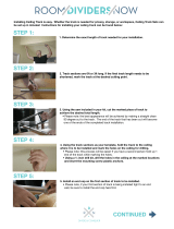
STEP 4: Door Header Tube Assembly
Assemble the Long Door Header Tube (A) and the Short Door Header Tube (B) as shown. Do not fasten the joints
with screws at this time. Place the assembly on the ground with the 2” side facing up and fasten an Angle Bracket
(H) on each end with the Outside of the bracket flush with the end of the tube. Use (3) #12 x 3/4” self drilling screws.
G
A
B
F
F
#12 x 3/4”
Self-Drilling Screw
STEP 5: Attaching the Door Header Assembly
Make a mark on the door opening side of both
Door Vertical Tubes (D) at 81 3/4” from the bottom
of the L-Sections.
Note: You will need two people to lift, position and
attach the Door Header Assembly.
Lift the Door Header, flip it over so that the
brackets are on the bottom side and line up the
bottom ends with the marks on the Door Verticals.
Attach the Angle Brackets on the ends of the Door
Header to the Door Verticals with (3)
#12 x 3/4” self-drilling screws per bracket.
Now, set the door header tubes straight and attach
the joint with two screws on the inside of the build-
ing.
PAGE 9
81 3/4"
F
BRACKETS ON
BOTTOM OF
HEADER
Attach joint with 2 screws
on inside of building

PAGE 10
INSTALLING TRIM ON THE GARAGE DOOR FRAME
ANGLE TRIM INSTALLATION:
Cut two pieces of Angle Trim to fit from the concrete slab to the top of the door jamb (bottom of the door header) for each
door. This will trim out the door jambs.
If you have one 8’ wide garage door you will be using (1) 8’ piece of Angle Trim for the header.
Fasten the Angle Trim with Painted #12 x 1” Self-Drilling Screws with Rubber Washers every 2’.
ORDER OF INSTALLATION: (1) ANGLE TRIM, (2) J-TRIM, (3) SIDE J-TRIM, (4) TOP J-TRIM
2”
1 1/2”
ANGLE TRIM
CUT DOOR JAMB ANGLE
TRIM TO FIT FROM SLAB
TO BOTTOM OF DOOR
HEADER.
DETAIL
USE #12 X1” PAINTED, SELF
DRILLING SCREW WITH RUBBER
WASHER.
FRONT
FRONT
#12 X 1” PAINTED, SELF-DRILLING SCREW
WITH RUBBER WASHER

PAGE 11
INSTALLATION OF J-TRIM AROUND GARAGE OVERHEAD DOOR:
Top J-Trim: Attach one 8’ piece of J-Trim to fit from the bottom of the sheeting ledge to the top of the door jamb (bottom
of the door header). This will be the side J-Trim. If your building is on a slab with no sheeting ledge, cut the trim to fit from
the slab to the under side of the door header.
Sides J-Trim: If you have a 7’ tall door cut a piece of J-Trim 85” long and cut a 1” slit in one end as shown in detail. The
slit will create a tab that will fold into the door header top J-Trim. See illustration.
Attach the Side J-Trim first at both ends and two additional places equally spaced from top to bottom with Pan Head Self-
Drilling Screws. See illustration below for location of Side J-Trim.
Place the Top J-Trim on first, the slide the Side J-Trim tab in the top J-Trim. Fold the end tabs, that you created with the
1” slits, over into the J-Trim channel and attach the at both ends and two on three places down the length with Pan Head,
Self-Drilling Screws. (Be sure to place one screw in the overlap joint if you have one.)
NOTE: Inside foam closure strips are provided to put between the sheet metal and J-trim around the garage door.
J-TRIM
OUTSIDE OF BUILDING
FRONT
DOOR HEADER
MAKE TWO CUTS 1”
LONG AND FOLD TAB
DOWN INTO J-CHANNEL
ON TOP END
1” SLIT
PAN HEAD, SELF-DRILLING SCREW
DOOR JAMB, TOP VIEW, RIGHT SIDE OF DOOR
TOP J-TRIM
J-TRIM
SIDE J-TRIM

Step 1: Cutting panels for both sides of door
The four panels to be attached on both sides of the door will be cut from the 8' panel provided. Use the layout below
to mark and cut out panels 1 through 4.
Step 2: Installing the first 4 panels (2’ panel)
Start the installation of front panels with panel 1 on the front left and panel 2 on the front right of the building at the
bottom. The panels should be raised 1/8” off the ground or concrete slab. Make sure that your building is square and
that the panels are flush with the outside of the building frame. Fasten the panels to the building frame with Painted
Self-Drilling screws with rubber washers (N) above and below each major rib. Now, install panels 3 and 4 above
panels 1 and 2 as shown overlap each successive panel as you work your way up the frame. (See overlap/under lap
rib detail)
Step 3: Installation of panel 5 and 6 (6'-1” panel)
Set panels 5 and 6 in place above panels 2 and 3 and mark on the back of the panel the door opening and roof con-
tour. Remove the panel and use tin snips or electric nibbler to trim panels 5 and 6 to fit the building. Now put the pan-
els back in place and attach with painted self-drilling screws.
FLAN
PAINTED
SELF-DRILLING
SCREWS
OVERLAP RIB
BOTTOM OF
UPPER PANEL
UNDER LAP RIB
TOP OF LOWER PANEL
RIB DETAIL
PAGE 10
INSTALLATION OF SHEET METAL ON FRONT ENCLOSURE
(4) 2' and (2) 6'-1” PANELS
NOTE: The sheet metal on the front and back of the building should be installed before the roof and sides.
4
3
2
1
6 5

INSTALLATION OF SHEET METAL PANELS ON THE SIDE OF BUILDING
(8) 9’-2” panels on an 18’ long x 7’ side wall frame.
These instructions assume that the roof panels are installed on the building and the screws above the
bottom rib have not yet been installed.
STEP 1: Insert the top (under lap) rib of one of the 9'-2” panels under the bottom rib of the lower roof panel at the
back of the building. This will be panel 1. Now, flush panel 1 to the back edge of the building frame and fasten the
panel to the corner frame post and the next frame post back with 3/4” self drilling screws with rubber washers.
Screws should be placed above and below each major rib. Do not install screws next to the top or bottom ribs at
this time. Do not place any screws at this time in the center frame post.
STEP 2: Install panel 2 in the same manner as panel 1 with the front edge of the panel flush with the front edge of the
building frame. Panel 2 should overlap panel one in the center of the building. (If you removed screws from the lower
roof panel, reinstall them at this time.) Install screws above and below each major rib. Do not install screws above
the bottom rib at this time.
STEP 3: Panels 3, 4, and 7 and 8 (from the other side, not shown) will be partial panels. To create these panels, cut
the panels 29 3/8" down from the top side of 4 of the 10' panels. Be sure to cut the 29 3/8" section measuring
from the top under lap edge
(see the under lap / overlap detail). You should check the measurement on your
building.
Now, Install panels 3 and 4 under panels 1 and 2 and secure with screws above and below all major ribs at this time.
Note: Panel 4 (the front panel) should overlap panel 3 (the back panel). Repeat assembly on other side of
building with panels 5, 6, 7, and 8 (not shown in illustration).
RIB DETAIL
OVERLAP RIB
BOTTOM OF UPPER
PANEL
UNDER LAP RIB
TOP OF LOWER
PANEL
3/4" SELF-DRILLING
SCREW WITH RUBBER WASHER
PAGE 11

INSTALL CORNER TRIM
Before you install the corner trim you must install Outside Foam Closures. The foam closured are
grey foam strips with notches cut out to match the contour of the sheet metal panel ribs. The clo-
sures have an adhesive strip on one surface. Peal off the protective paper and install the strips to the
sheet metal panels in the corners of the building as shown. The corner trim for your building is angle
trim 3” x 3” x 8’ long. You will have to cut the corner trim to fit. Screw the trim to the building with #12
x 1” self-drilling screws painted the color of the trim. Place the screws in the trim to hit the center of
every other major rib in the sheet metal panels. Attach with screws in the center of every other rib as
shown.
3”
3”
3” X 3” ANGLE TRIM
TOP VIEW
PAGE 14
OUTSIDE CLOSURE ON ALL 4
CORNERS OF THE BUILDING

INSTALLING YOUR GARAGE DOOR IN A VERSATUBE FRAME
Note that the Versatube frame is all steel with no overhead ceiling joist. You must deviate from the door manufacturer’s
instructions to install the garage door in the Versatube frame. The following is a list of the installation steps that will be
different from the door manufacturer’s assembly instructions:
1. It is not necessary for you to frame out your door opening with 2 x 6 lumber. Track brackets will be attached directly
to the steel door frame.
2. If you have a door with torsion springs instead of a extension springs you will need to attach a center vertical over the
door header if one is not provided. 16’ wide doors will come with a center vertical tube 2” square.
3. You will fasten all brackets an channels to the Versatube frame with #12 x 1” self-drilling screws instead of the lag
screws provided with your door.
4. The garage door manufacturer’s instructions call for assembling all of the door sections one at a time and using 3”
nails bent over to hold the sections in place. With the Versatube frame you will assemble only the first or bottom door
section and use it as a guide to locate and attach the vertical tracks to the door opening.
If you are installing a garage door in a 12’ x 18’ x 7’ or 7 1/2’ Versatube frame. You should have a low headroom double
track or a conversion kit provided to allow for only 4 1/2” of headroom. In ether case you will need to cut the vertical door
tracks down to 66 3/4” in height and drill new mounting holes for the flag bracket. Follow the manufacturers instructions
for assembly of the low headroom double rail or conversion kit. (the 66 3/4” dimension is for horizontal tracks with a 12”
radius bend. Some door tracks have a 9” radius bend. If you have a 9” radius track cut the straight vertical tracks down to
69 3/4”. For a 15” track cut the vertical tracks down to 63 3/4”. (See door manufacturers instructions to determine track
radius size measured from the bottom of the bend to the center of the horizontal track.)
TIP: You should have two people to install the garage door.
Step 1 Low headroom kit
If you have a low headroom track or kit, cut the left and right vertical rail down to 66 3/4” high for a 12” radius track,
69 3/4” for 9” radius, and 63 3/4’ for a 15” radius. Cut off the top of the rail. See illustrations in the manufacturer’s instruc-
tions.
Step 2 Track and Flag Brackets to Vertical Track
Install mounting brackets and flag bracket to the vertical rails according to the manufacturer’s instructions.
Step 3 Assemble Door Section 1
Assemble door section #1 according to the manufacturer’s instructions including the bottom weather strip, the bottom
wheel brackets and the correct hinges. Insert 4 rollers into bottom brackets and hinges and place the first door section in
the door opening with the front of the door flush with the back of the door frame. Center the door side to side. One person
must hold the door in place or brace it up with something on both sides.
Step 4 Installing Vertical Door Tracks
Slide the left vertical door track onto the wheels. Use your level to plumb the track and fasten the bottom track bracket to
the door frame with a #12 x 1” self-drilling screw ( the same screws used to assemble your frame).
Plumb the track and attach the next higher bracket to the door frame. Continue to plumb and attach all brackets and flag
bracket to the frame with self–drilling screws. When all brackets are installed go back and install one additional screw in
DOOR OPENING FRAME (JAMB)
GARAGE DOOR CENTERED
IN OPENING
BOTTOM BRACKET
ROLLER
TRACK
TRACK BRACKET
SELF-DRILLING SCREW
PAGE 15

Step 5 Installing Additional Door Sections
Follow the door manufacturer’s instructions and assemble door section 2. Note that each door section uses a different
height hinge at the ends of the door and the same size hinge in the center of the door.
When the second door section is assembled, install the rollers and install the door section into the vertical door tracks
sliding it down from the top of the tracks. With the section in place attach the door hinges connecting section one to sec-
tion two.
Repeat this assembly for door section three. If your door is taller than 7’ install all but the top section. The top section will
be installed after the horizontal track (and low headroom kit if required) is installed.
Step 6 Installing Low Headroom Kit or Double Track and Horizontal Door Tracks
Follow the instructions provided by the manufacturer of the Low Headroom Kit to assemble the kit to the horizontal tracks.
Note: The Perforated Angle and the 5/16” x 3/4” hex bolts, lock washers and nuts are not provided and must be pur-
chased separately. The length of angle you will need will depend on building height and door configuration. You will need
8 of the hex bolts, lock washers and nuts. You should have enough self-drilling screws left over from the building
assembly.
If the Versatube building that you have has 4’ on center frame spacing you will tie the back of the horizontal tracks up to
the rafter above at the end of the tracks. If the your building has the frame sections on 4 1/2’ or 5’ centers you will have to
add an extension
piece of perforated angle (1 1/2” x 1 1/2” x 16 GA.) to your tracks. This extension will allow you to
connect the vertical perforated angle to the rafter above. (See illustration on next page)
For 4 1/2’ on center buildings cut two pieces of Perforated Angle (1 1/2” x 1 1/2” x 16 GA.) 16” long. For 5’ on center
frames cut the angle lengths to 28”. Measure from the back of the horizontal tracks 8 3/4” and make a mark on the out-
side of the track. Place the extension angle piece on the track as shown with the end of the angle extension lined up with
your mark. Clamp the track and extension angle together and drill two 5/16” hole through the door track using the two of
the holes in the perforated angle as a guide. (See illustration)
8 3/4”
7 1/4” for 4’ ON CENTER FRAME
19 1/4” for 5’ ON CENTER FRAME
PERFORATED
EXTENSION
ANGLE
HORIZONTAL DOOR
TRACK
5/16” X 3/4”
HEX BOLT
NUT
SPLIT LOCK WASHER
DRILL HOLES IN DOOR TRACK
Step 7
Attach the Horizontal Tracks to the Vertical Tracks following the manufacturer’s instructions. If you are attaching a low
headroom kit you will also refer to the instructions included with that kit. To temporally support the back of the tracks use
a string tied to the back of the perforated angle extensions. You should be able to find a place to lace the string through
the sheet metal and over the rafter. If you prefer, you can drive a self-drilling screw into the side of the rafter part way and
tie the string to the screw.
The back of the perforated angle extension (that you attached to the horizontal tracks) will be fastened vertically to the
rafter above with a piece of perforated angle and a brace piece placed at an angle. Use 5/16” x 3/4” hex bolts with lock
washers and nuts to attach the angle pieces together and #12 x 3/4” painted self-drilling screws with rubber washer (the
same screws you used to attach the sheet metal on the building) to attach the perforated angles to the rafter above.
Note: The perforated angle and 5/16” x 3/4” hex bolts, lock washers and nuts are not provided with the garage door or
conversion kit. They must be purchased separately. See illustration on next page.
PAGE 16

#12 x 3/4” PAINTED
SELF-DRILLING SCREW
WITH RUBBER WASHER
EYE HOOK WITH 2
LOCKING NUTS
PROVIDED WITH
GARAGE DOOR
(HOOK FOR SPRING)
RAFTER
5/16” X 3/4” HEX BOLT,
LOCK WASHER & NUT
#12 x 3/4” PAINTED
SELF-DRILLING SCREW
WITH RUBBER WASHER
5/16” X 3/4” HEX BOLT,
LOCK WASHER & NUT
RAFTER
DOOR TRACK WITH
EXTENSION ANGLE
ATTACHMENT OF DOOR TRACK WITH EXTEN-
SION ANGLE TO RAFTER IN 12’ WIDE BUILDING
WITH A LOW HEADROOM KIT INSTALLED.
ATTACHMENT OF DOOR TRACK WITH EXTEN-
SION ANGLE TO RAFTER IN BUILDING WITHOUT
A LOW HEADROOM KIT INSTALLED.
Before you start, make sure that the tracks are level
and square to the front of the building. Use your level
to set the track level and measure the diagonals from
the back of one track to the front of the other. The
diagonals must be equal. See illustration in door
manufacturer’s instructions.
Cut a piece of perforated angle to fit vertically as
shown and fasten it to the track extension angle with
a 5/16” x 3/4” hex bolt, lock washer and nut. Fasten
the top portion to the rafter with two Painted self-
drilling screws with rubber washers (the same screws
you used to attach the sheet metal to your building).
Now, cut a piece of perforated angle to create an
angle brace as shown and attach it to the track exten-
sion just above the extension with a 5/16” x 3/4” hex
bolt, lock washer and nut. Attach the brace to the
rafter with a painted self-drilling screw.
IF YOUR BUILDING HAS FRAME SECTIONS ON 4’ CENTERS, YOU WILL NOT NEED A PERFORATED TRACK
EXTENSION. YOU WILL ATTACH THE END OF THE DOOR TRACK TO THE RAFTER WITH A VERTICAL BRACE
AND AN ANGLE BRACE AS SHOWN ABOVE RIGHT. THE VERTICAL BRACE WILL ATTACH TO THE LARGE
HOLE AT THE BACK OF THE DOOR TRACK.
ATTACHING THE SPRING HOOK (EYE BOLT)
With a low headroom kit you will mount the spring
hook to the vertical brace as high as you can above
the track extension. Place a flanged, locking hex nut
on the eye bolt the full extension of the threads with
the flange to the rear. Insert the bolt through the verti-
cal brace and install another flanged hex nut as
shown. Tighten the nuts.
ATTACHING THE SPRING HOOK (EYE BOLT)
The spring hook should be attached to the vertical
brace about 12” above the track extension. Place a
flanged, locking hex nut on the eye bolt the full exten-
sion of the threads with the flange to the rear. Insert
the bolt through the vertical brace and install another
flanged hex nut as shown. Tighten the nuts.
EYE HOOK WITH 2
LOCKING NUTS
PROVIDED WITH
GARAGE DOOR
(HOOK FOR SPRING)
PAGE 17

INSTALLING THE TOP DOOR SECTION
With the door tracks (and low headroom kit if required) installed it is now time to install the last or top door section.
Place the last door section on top of the section before. Center it side to side and clamp the bottom of the top section to
the lower section or have a helper hold the bottom of the section in place while you attach the hinges connecting the sec-
tions at the center and both ends.
Take a roller, lace it into the track or low headroom track, place the top roller bracket onto the roller shaft, position the
bracket on the top door section and attach it to the door with sheet metal screw. Repeat on other end of top door section.
TOP BRACKET IN LOW HEADROOM KIT
TOP BRACKET THAT COMES WITH GA-
RAGE DOOR. LOCATE 3 1/4” DOWN
FROM TOP OF DOOR
PLACE ROLLER IN
TRACK.
PLACE BRACKET ON
ROLLER SHAFT.
MOUNT TO DOOR
PLACE ROLLER IN
TRACK.
PLACE BRACKET ON
ROLLER SHAFT.
MOUNT TO DOOR
CLAMP OR HOLD DOOR SECTIONS
TOGETHER WHILE INSTALLING
HINGES.
INSTALLING DOOR SEALS
Door weather seal strips have been provided to go on the
door frame (outside the door) both sides and top of the door
to seal out wind and rain.
Cut the one seal to fit your door header and fasten it to the
Versatube frame with painted #12 x 3/4” self-drilling screws
with rubber washers. Place the screws about 12” apart.
Locate the weather seal strip so that the flexible seal portion
presses lightly against the front of the door. Now cut to side
pieces of trim to go from the bottom side of the top trim to
the concrete slab. Fasten the side pieces as you did the top
seal.
Make all necessary adjustments to the track brackets to allow the door operate smoothly. See the door manu-
facturer’s instructions for all adjustments.
Refer to the door manufacturer’s instructions for spring installation. If you have a torsion spring door
, Mount the
center bearing plate with #12 x 3/4” painted, self-drilling screws with rubber washers instead of 5/16” x 1 1/2” lag
screws. Pre drill one additional 1/4” hole in the plate between the existing holes prior to mounting. Use 3 screws.
GARAGE DOOR
WEATHER SEAL
#12 X 1” SELF-DRILLING SCREW
DOOR FRAME
SIDE VIEW
PAGE 18
/