Prince Castle 740-T8 Operating instructions

Type
Operating instructions

This manual is also suitable for

OPERATING
INSTRUCTIONS
Single Function Timers
Model No. 740-T, 740-TJ &
740-TF Series
355 East Kehoe Blvd. ! Carol Stream, IL 60188
Tel: (630) 462-8800 ! Fax: (630) 462-1460
Toll Free: 1-800-PCASTLE
TABLE OF CONTENTS PAGE
Installation..................................................................... 2
Programming................................................................. 2
Operation ....................................................................... 3
Cleaning ........................................................................ 4
Parts List....................................................................... 4
Exploded View .............................................................. 5
Troubleshooting ............................................................ 5
Wiring Diagrams ........................................................... 6
Prince Castle’s second generation of Merlin Timers
feature a new slim design which gives you mounting
flexibility. The 740 Series Timers are designed so
each channel can be programmed independently,
and used simultaneously. The timers are simple to
program and simple to use. The push of a button
activates each channel, and a alarm and multi-
colored flashing channel buttons alert the operator
when timing is complete.
ELECTRICAL
740-TSeries 740-TJ Series
120 Volts 100 Volts
50-60 Hz 50/60 Hz
740-TF Series
220-240 Volts
50/60 Hz
Model 740-T8
This product is warranted to be free from defects in material
and/or workmanship for a period of 1 year from date of original
installation, not to exceed 18 months from the date of
manufacture.
Any component which proves to be faulty in material and/or
workmanship will be replaced or repaired (at the option of
Prince Castle, Inc.) without cost to the customer for parts and
labor. This equipment is portable; charges for on-location
service (e.g., trip charges, mileage) are not included in the
provisions of this warranty.
This warranty is subject to the following exceptions/conditions:
Use of any non-genuine Prince Castle parts voids this
warranty.
All labor to be performed during regular work hours.
Overtime premium (the incremental amount) will be charged
to the customer.
Damage caused by carelessness, neglect and/or abuse
(e.g., dropping, tampering or altering parts, equipment
damaged in shipment, by fire, flood or an act of God) is not
covered under this warranty.
All problems due to operation at voltages other than that
specified on equipment nameplates are not covered by this
warranty. Conversion to correct voltage is the customer’s
responsibility.
This equipment must be serviced by Prince Castle
Authorized Service Agency or a Prince Castle Service
Technician during the warranty period.
LIMITED WARRANTY
740-517revB
Printed in USA 3/06 © 2006
INSTALLATION
1. After you have removed the timer from the carton,
inspect the unit for signs of damage. If there is
damage to the unit:
! Notify carrier within 24 hours after delivery.
! Save carton and packing materials for inspection
purposes.
! Contact your local Prince Castle dealer or, if
purchased directly, the Prince Castle Customer
Sales Department at 1-630-462-8800 to arrange
for a replacement to be sent.
2. Verify that all parts have been received. Mounting
brackets and hardware are provided.
3. To mount the timer, place mounting brackets in de-
sired location. Scribe location of mounting holes,
center punch, and drill holes. Attach timer to mount-
ing brackets placing star washer between bracket and
timer.
DISPLAYS AND INDICATORS
Shows the time for the selected channel
number.
Shows the channel number selected
and in use. (The 740-T2 model does
not have this display.)
Indicates the time value is in Hours and
Minutes.
Indicates that the time value is in
Minutes and Seconds.
Located above each channel timer
button, these lights change color
depending on the stage of the count-
down. Green = first 70% of countdown,
Yellow = next 20% countdown,
Red = last 10% of countdown.
CONTROLS
The 740-T2 has 2 channels, the 740-T4
has 4 channels, the 740-T8 has 8
channels and the 740-T12 has 12
channels.
In the program mode, it increases time
values for each channel . In the Run
Mode, it is used in conjunction with logo
button to increase the volume.
In the program mode, it decreases time
values for each channel . In the run
mode, it is used in conjunction with logo
button to decrease the volume.
Activates Program Mode and used to
adjust the alarm sound level.
PROGRAMMING
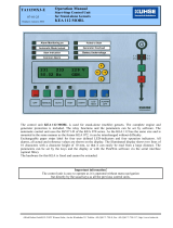
1. To program, press and hold the PRINCE CASTLE
logo for six seconds. The TIME display changes
from ---- to Prog, and a beep will sound.
See figure 1.
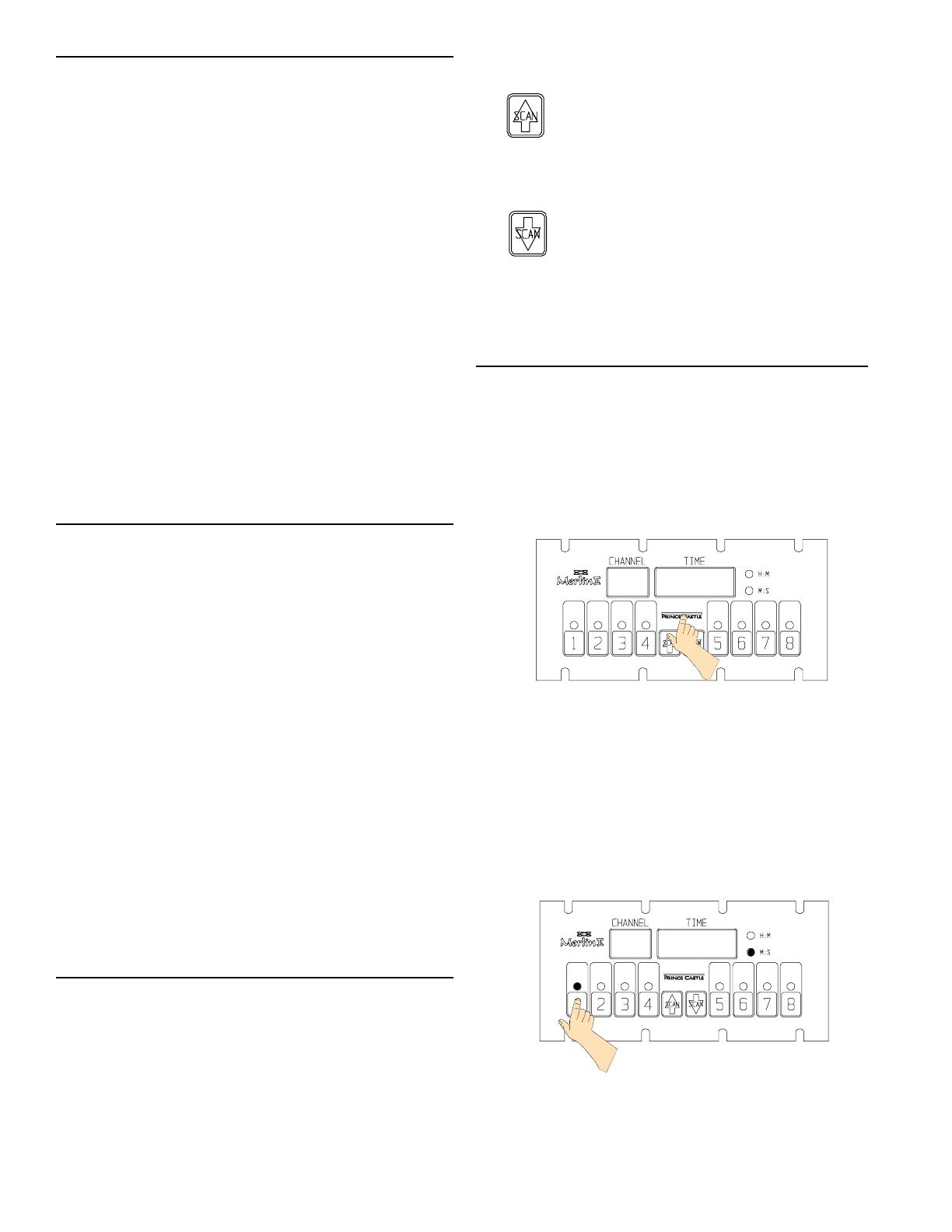
2. Select and press the timer channel to be pro-
grammed. The LED indicator for the selected
button will turn yellow and a beep will sound. The
selected channel number will be displayed in the
CHANNEL display, the current programmed time
for that channel will be displayed in the TIME
display, and the time value will indicate either H:M
OR M:S. See figure 2.
3. To change the program time for the selected
channel, use the SCAN/UP Arrow or the SCAN/
DOWN Arrow button.
2
Channel
(Timer)
SCAN/UP
ARROW
SCAN/DOWN
ARROW
PRINCE
CASTLE
Logo
TIME
Display
CHANNEL
Display
H:M
M:S
LED
Indicators
figure 1
P r o g
1
8:00
figure 2
740-517revB
Printed in USA 3/06 © 2006
3
IMPORTANT: To change from Minutes and Seconds
M:S to Hours and Minutes H:M. press and hold the
SCAN/UP Button. When the display reaches 59:59 it
will automatically change to 1:00 Hour and the LED will
switch from M:S to H:M. The program value for the
H:M indicator is from 1:00 hour to 17 hours: 59 min-
utes. See figures 3 and 4.
4. To program another channel, press the desired
channel button.Repeat programming procedures in
steps 2 and 3 above. See figure 5.
5. When finished progamming each desired channel,
momentarily press the PRINCE CASTLE logo to
end the Program Mode. This saves the program
changes you have made for all channels.
See figure 6.
6. This timer is equipped with programmable
volume(S-3, S-2, S-1 & OFF) levels. The timer
volume can be adjusted by pressing and holding
(for less than 6 seconds) the Prince Castle
Logo and simultaneously either the UP or
DOWN ARROW buttons. The display will show
either S-3 (High Volume), S-2 (Medium Volume),
S-1 (Low Volume) or OFF (No alarm, only key
press feedback tones). To increase the volume
press the UP ARROW, to decrease the volume
press the DOWN ARROW. See figure 7.
OPERATION
1. Press a channel button to activate a timing cycle.
(All channels can be activated and running at the
same time.) The time channel number with the
least amount of time remaining will be displayed in
the CHANNEL display, its time remaining will
countdown in the TIME display, and the time value
M:S or H:M will be illuminated. See figure 8.
2. Press the desired channel button three times within
five seconds to cancel an active timing cycle.
IMPORTANT: The channel timer button’s multi-colored
LED indicator shows the status of the timer. The
indicator has three colors: green, yellow, and red. The
LED will be green during the first 70% of the count-
down. It changes to yellow during the next 20% of the
countdown. It will be red during the final 10% of the
countdown, and will start flashing red once the time
has run out.
figure 3
figure 4
1
59:59
1
1:00
2
3:00
- - - -
figure 5
figure 6
figure 7
.25
figure 8
740-517revB
Printed in USA 3/06 © 2006
3. The timer will countdown from the programmed
value to zero. At zero, the display flashes End and
the alarm sounds. See figure 9.
IMPORTANT:There are three indicators that signal the
operator when the timing cycle is complete: The
CHANNEL display shows the channel associated with
the alarm. The TIME display shows End. The LED
indictor in the channel button flashes red.
4. When the timing cycle is complete, and the alarm
sounds, press the channel button with the flashing
red indicator to cancel the alarm. See figure 10.
5. The scan feature is used to check the time values on
other active channels. There are two different ways
to scan active channels. Press the SCAN/UP or
SCAN/DOWN button.Or press any of the active
timer CHANNEL buttons. If no other button is
pressed within 5 seconds, the display will change to
show the timer with the least amount of time left.
See figure 11.
CLEANING
1. Do not allow grease to build up on the timer, wipe it
down daily with clean damp cloth.
IMPORTANT: Do not use abrasive or chemical cleaners
on your timer, this may cause damage to the overlay.
PART LIST
ITEM PART NUMBER
DESCRIPTION
1 69-079S Rivet Plastic Push Pin
2 69-080 Self Retaining Nut
3 73-014 Hex Nut #4-40 S.S.
4 73-021 Hex Nut #8-32 S.S.
5 88-653-2-4S Speaker Assy.
88-653-2-11S Speaker Assy. (740-T4)
6 735-240S Switch Panel Assy.
(740-T2)
735-211S Switch Panel Assy.
(740-T4)
735-205S Switch Panel Assy.
(740-T8)
735-208S Switch Panel Assy.
(740-T12)
7 735-237 Front Bezel (740-T2)
735-223 Front Bezel (740-T4)
735-226 Front Bezel (740-T8)
735-229 Front Bezel (740-T12)
8 735-238 Rear Cover (740-T2)
735-224 Rear Cover (740-T4)
735-227 Rear Cover (740-T8)
735-230 Rear Cover (740-T12)
9 740-9S Main P.C.Board
(740-T2)
740-218S Main P.C.Board
(740-T4,740-T8 &
740-T12)
10 740-13S P.C.Board Wing
(740-T8)
740-15S P.C.Board Wing
(740-T12)
11 70-048S Knobs (with washers)
12 79-079 Washer
13 72-292S Power Supply (110 V)*
72-293-01JS Power Supply (200 V)
72-293-04FS Power Supply (220-240 V)
* 735-241 Wall Mounting Bracket
*735-242 Table Mounting Bracket
4
figure 9
1
End
1
End
figure 10
figure 11
3
4:00
*72-335S Power Supply
(740-T12PM, 740-T12AMPM, 110V)
*740-282S Switch Panel Assy. (740-T12PM)
*740-407S Switch Panel Assy. (740-T12AMPM)
740-517revB
Printed in USA 3/06 © 2006
EXPLODED VIEW
1
2
3
4 5
6
7
8
9
10
10
11
11
12
12
13
TROUBLESHOOTING GUIDE
5
A. No displays or indicators lit. Unit unplugged. Plug unit in.
Store's circuit breaker blown. Reset breaker.
Defective transformer. Replace Main Circuit Board.
Circuit inoperable. Replace Main Circuit Board.
B. Absence of Audio Alarm. Speaker inoperable. Replace Speaker.
Circuit inoperable. Replace Main Circuit Board.
C. Unit will not enter program All channels are still counting. Wait until channels are in stop
mode. Display does mode.
not show "Prog". Logo Switch inoperable. Replace Switch Panel.
D. Unit enters program mode. The channel is still counting. Wait until channel is in stop mode.
Display shows "Prog", but Arrow Switch inoperable. Replace Switch Panel.
cannot change times. Circuit inoperable. Replace Main Circuit Board.
E. Unable to start, stop, or store Circuit inoperable. Replace Switch Panel. If
timer presets in program mode. problem persists, replace Main
Missing or abnormal characters Circuit Board.
in displays.
F. “8888” flashing in display with Unit is in test mode Unplug timer, hold in both the Up
a constant audio alarm. and Down arrows while plugging in.
This will exit timer from test mode.
CAUSE
SOLUTION
PROBLEM
740-517revB
Printed in USA 3/06 © 2006
WIRING DIAGRAM 740-T4,T8 &T12
WIRING DIAGRAM 740-T2
6
740-517revB
Printed in USA 3/06 © 2006
  • Page 1 1
  • Page 2 2
  • Page 3 3
  • Page 4 4
  • Page 5 5
  • Page 6 6

Prince Castle 740-T8 Operating instructions

Type
Operating instructions
This manual is also suitable for

Ask a question and I''ll find the answer in the document

Finding information in a document is now easier with AI