Page is loading ...

Digital Controller
IMR01W07-E4
This manual describes the connection method with host computer, communication
parameters and communication data (except for parameters in Engineering Mode) of
the FB400/FB900. For detailed host communication such as communication data in
the Engineering mode, protocol and Modbus data mapping description, refer to the
FB100/FB400/FB900 Communication Instruction Manual (IMR01W04-E).
The Communication Instruction Manual can be downloaded from the official
RKC website: http://www.rkcinst.com/english/manual_load.htm.
1. OUTLINE
Digital Controller FB400/FB900 (hereafter, called controller) interfaces with the host
computer via RKC or Modbus communication protocols. In addition, there is the
Modbus data mapping function which enables high-speed communication by
collecting only the data to be communicated at all times in the specified address area.
Communication port
There are two communication ports: Communication 1 and Communication 2.
Communication 1 is used for host communication.
Communication 2 is used for intercontroller communication, but can be also used for
host communication.
When Communication 2 is used for host communication, refer to the FB100/
FB400/FB900 Communication Instruction Manual (IMR01W04-E).
Communication interface
Communication 1 interface: RS-422A, RS-485, RS-232C
Communication 2 interface: RS-485
(When Communication 1 is used for RS-422A, no
Communication 2 can be used.)
2. WIRING
Make sure that lugs or unshielded cables of the communication
terminals are not touched to the screw heads, lugs, or unshielded cables
of the power supply terminals to prevent electric shock or instrument
failure. Use additional care when two lugs are screwed to one
communication terminal.
The cable and termination resistor(s) must be provided by the customer.
2.1 RS-485
Communication terminal number and signal details
Terminal No. Signal name Symbol
25 Signal ground SG
26 Send data/Receive data T/R (A)
27 Send data/Receive data T/R (B)
Wiring method
When the interface of host computer (Master) is RS-485
Host computer (Master)
RS-485
Paired wire
Shielded twisted
pair wire
Controller (Slave)
Communication terminals
(communication 1 side)
Controller (Slave)
*R
*R
25
T/R (B)
T/R (A)
26
27
SG
25
T/R (B)
T/R (A) 26
27
SG
T/R (B)
T/R (A)
SG
Communication terminals
(communication 1 side)
Screw size: M3
×
7 (with 5.8
×
5.8 square washer)
Recommended tightening torque:
0.4 N
・
m (4 kgf
・
cm)
Specified solderless terminals:
Manufactured by J.S.T MFG CO., LTD.
Circular terminal with isolation V1.25-MS3
(M3 screw, width 5.5 mm, hole diameter 3.2 mm)
*R: Termination resistors (Example: 120
1/2 W)
If communication errors occur frequently due to
the operation environment or the communication distance,
connect termination resistors.
Maximum connections: Up to 31 controllers
(
)
()
()
()
(
)
()
When the host computer (Master) has a USB connector
Connect the USB communication converter between the host computer and the controller.
RS-485
Paired wire
Shielded twisted
pair wire
Controller (Slave)
*R
25
T/R (B)
T/R (A)
26
27
SG
(
)
(
)
Controller (Slave)
25
T/R (B)
T/R (A)
26
27
SG
Host computer (Master)
USB communication converter
COM-K (RKC product)
Connect to
USB port
USB cable
(COM-K accessory)
Connect to
USB connector
of COM-K
The termination
resistor is built
into the COM-K.
1
SG
2
4
3
5
T/R (A)
T/R (B)
Unused
Unused
(
)
(
)
Screw size: M3
×
7 (with 5.8
×
5.8 square washer)
Recommended tightening torque:
0.4 N
・
m (4 kgf
・
cm)
Specified solderless terminals:
Manufactured by J.S.T MFG CO., LTD.
Circular terminal with isolation V1.25-MS3
(M3 screw, width 5.5 mm, hole diameter 3.2 mm)
*R: Termination resistors (Example: 120
1/2 W)
If communication errors occur frequently due to
the operation environment or the communication distance,
connect termination resistors.
Maximum connections: Up to 31 instruments
Communication terminals
(Communication 1 side)
Communication terminals
(Communication 1 side)
For the COM-K, refer to the COM-K Instruction Manual (IMR01Z01-E).
2.2 RS-422A
Communication terminal number and signal details
Terminal No. Signal name Symbol Terminal No. Signal name Symbol
25 Signal ground SG 28 Receive data R (A)
26 Send data T (A) 29 Receive data R (B)
27 Send data T (B)
Wiring method
RS-422A
Paired wire
Shielded twisted
pair wire
T (B)
T (A)
R (B)
R (A)
SG25
26
27
28
29
SG
T (B)
T (A)
R
(B)
R
(A)
25
26
27
28
29
SG
T (B)
T (A)
R
(B)
R
(A)
Screw size: M3
×
7 (with 5.8
×
5.8 square washer)
Recommended tightening torque:
0.4 N
・
m (4 kgf
・
cm)
Specified solderless terminals:
Manufactured by J.S.T MFG CO., LTD.
Circular terminal with isolation V1.25-MS3
(M3 screw, width 5.5 mm, hole diameter 3.2 mm)
*R: Termination resistors (Example: 120
1/2 W)
If communication errors occur frequently due to
the operation environment or the communication distance,
connect termination resistors.
Maximum connections: Up to 31 controllers
Host computer (Master)
Controller (Slave)
Communication terminals
(communication 1 side)
Controller (Slave)
Communication terminals
(communication 1 side)
()
()
()
()
()
()
()
()
(
)
(
)
()
()
*R
*R
*R
*R
Using a USB communication converter COM-K (RKC product) enables
connection with the USB port of the host computer.
2.3 RS-232C
Communication terminal number and signal details
Terminal No. Signal name Symbol
25 Signal ground SG (GND)
26 Send data SD (TXD)
27 Receive data RD (RXD)
Wiring method
RS-232C
Shielded wire
SD (TXD)
RD (RXD)
SG (GND)
RS (RTS)
CS (CTS)
* Short RS and CS within connector.
*
SD (TXD)
RD (RXD)
SG (GND)
25
26
27
Screw size: M3
×
7 (with 5.8
×
5.8 square washer)
Recommended tightening torque:
0.4 N
・
m (4 kgf
・
cm)
Specified solderless terminals:
Manufactured by J.S.T MFG CO., LTD.
Circular terminal with isolation V1.25-MS3
(M3 screw, width 5.5 mm, hole diameter 3.2 mm)
Host computer (Master)
Controller (Slave)
Communication terminals
(communication 1 side)
Number of connection: 1 controller
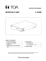
2.4 Connections for Loader Communication
Controller is equipped standard with a loader communication connector.
The controller loader communication connector, our COM-K USB communication converter
(sold separately), and a host computer can be connected with the appropriate cables.
Communication settings on the computer
(the following settings are all fixed)
Communication speed: 38400 bps
Address: 0
Start bit: 1
Data bit: 8
Parity bit: Without
Stop bit:
1
Host
computer
USB communication
converter COM-K
(RKC product)
Connect to USB port
of host computer
Connect
to USB
connector
The termination
resistor is built
into the COM-K.
Loader communication
cable (W-BV-01)
[Optional]
Connect to loader
communication
connector of
FB400
Connect to loader
communication
connector
USB cable
(COM-K accessory)
FB400
bottom view
The Loader port is only for parameter setup.
Loader communication corresponds to RKC communication (based on
ANSI X3.28-1976 subcategories 2.5 and A4).
For the COM-K, refer to the COM-K Instruction Manual (IMR01Z01-E).
3. SETTING
To establish communication parameters between host computer (master) and
controller (slave), it is necessary to set the device address (slave address),
communication speed, data bit configuration and interval time on each controller
(slave) in the Setup setting mode.
After all communication parameters are set, in order to make these
values thus set valid perform any of the following operations.
The power is turned on again after turning it off once.
The RUN/STOP mode is changed in RUN from STOP again after
changing it in STOP once.
Parameters which are not related to existing functions on the controller are
not displayed.
This instrument returns to the PV/SV monitor screen if no key operation is
performed for more than one minute.
This section describes the parameters which must be set for host
communication. For the screen operation and key operation, refer to the
FB400/FB900 Quick Operation Manual (IMR01W02-E).
Description of each parameters
Symbol Name Data Setting Description
Factory
set value
(Add1)
Device address 1
(Slave address 1)
0 to 99
Do not use the same device
address for more than one
controller in multi-drop
connection. Each controller must
have a unique address in
multi-drop connection.
In Modbus communication,
communication is not possible
when the address is 0.
0
(bPS1)
Communication
speed 1
2.4: 2400 bps
4.8: 4800 bps
9.6: 9600 bps
19.2: 19200 bps
38.4: 38400 bps
Set the same communication
speed for both the controller
(slave) and the host computer
(master).
19.2
(bIT1)
Data bit
configuration 1
Refer to data bit
configuration table
Set the same data bit
configuration for both the
controller (slave) and the host
computer (master).
8n1
(InT1)
Interval time 1 * 0 to 250 ms
The interval time for the controller
should be set to provide a time
for host computer to finish
sending all data including stop
bit and to switch the line to
receive status for the host.
10
* The interval time for the controller should be set to provide a time for host computer
to finish sending all data including stop bit and to switch the line to receive status for
the host. If the interval time between the two is too short, the controller may send
data before the host computer is ready to receive it. In this case, communication
transmission cannot be conducted correctly.
Data bit configuration table
Set
value
Data bit Parity bit Stop bit
Set
value
Data bit Parity bit Stop bit
8n1 8 Without 1 7n1
a
7 Without 1
8n2 8 Without 2 7n2
a
7 Without 2
8E1 8 Even 1 7E1
a
7 Even 1
8E2 8 Even 2 7E2
a
7 Even 2
8o1 8 Odd 1 7o1
a
7 Odd 1
8o2 8 Odd 2 7o2
a
7 Odd 2
a
When the Modbus communication protocol selected, this setting becomes invalid.
4. COMMUNICATION DATA LIST
Modbus register address
HEX: Hexadecimal DEC: Decimal
Attribute (A method of how communication data items are read or written
when viewed from the host computer is described)
RO: Read only data (Host computer
Controller)
R/W: Read and Write data (Host computer
Controller)
Data
Most significant
digit
Least significant
digit
…………
…
.
Bit 15
Bit 0
…………….……………………
RKC communication
ASCII code data of 7 digits
Modbus
16-bit data
Communication data (RKC communication/Modbus)
No. Name
RKC
Iden-
tifier
Modbus
register
address
Attri-
bute
Data range
Factory
set value
HEX
DEC
1
Model codes
ID RO Model code (character)
2
Measured value
(PV)
1
M1 0000 0 RO
Input scale low to
Input scale high
3
Current transformer 1
(CT1) input value
monitor
M3 0001 1 RO
CTL-6-P-N:
0.0 to 30.0A
CTL-12-S56-10L-N:
0.0 to 100.0 A
4
Current transformer 2
(CT2) input value
monitor
M4 0002 2 RO
5
Set value (SV)
monitor
1
MS 0003 3 RO
Setting limiter low to
Setting limiter high
6
Remote setting
(RS) input value
monitor
1
S2 0004 4 RO
Setting limiter low to
Setting limiter high
7 Burnout state monitor B1 0005 5 RO
0: OFF
1: ON
8
Burnout state monitor
of feedback
resistance input
B2 0006 6 RO
0: OFF
1: ON
9
Event 1 state monitor
AA 0007 7 RO
0: OFF
1: ON
10
Event 2 state monitor
AB 0008 8 RO
11
Event 3 state monitor
AC 0009 9 RO
12
Event 4 state monitor
AD 000A 10 RO
13
Heater break alarm 1
(HBA1) state monitor
AE 000B 11 RO
0: OFF
1: ON
14
Heater break alarm 2
(HBA2) state monitor
AF 000C 12 RO
15
Manipulated output
value (MV1) monitor
[heat-side]
O1 000D 13 RO
PID control or Heat/Cool PID
control:
5.0 to 105.0 %
Position proportioning PID
control with feedback
resistance (FBR) input:
0.0 to 100.0 %
16
Manipulated output
value (MV2) monitor
[cool-side]
O2 000E 14 RO 5.0 to 105.0 %
17 Error code ER 000F 15 RO
RKC communication
1: Adjustment data error
2: Back-up error
4: A/D conversion error
32: Custom data error
128: Watchdog timer
256: Stack overflow
2048: Program error (busy)
Modbus (Bit data)
Bit 0: Adjustment data error
Bit 1: Back-up error
Bit 2: A/D conversion error
Bit 3 to Bit 4: Unused
Bit 5: Custom data error
Bit 6: Unused
Bit 7: Watchdog timer
Bit 8: Stack overflow
Bit 9 to Bit 10: Unused
Bit 11: Program error (busy)
Bit 12 to Bit 15: Unused
Data 0: OFF 1: ON
[Decimal number: 0 to 4095]
1
Varies with the setting of the Decimal point position selection.
FB400/FB900
Communication
Quick Manual
All Rights Reserved, Copyright 2004, RKC INSTRUMENT INC.
To prevent electric shock or instrument failure, turn off the power
before connecting or disconnecting the instrument and peripheral
equipment.
!
WARNING

The first edition:
DEC.
2004 [IMQ00]
The fourth edition: MAR. 2012 [IMQ00]
®
RKC INSTRUMENT INC.
HEADQUARTERS: 16-6, KUGAHARA 5-CHOME, OHTA-KU TOKYO 146-8515 JAPAN
FAX: 03-3751-8585 (+81 3 3751 8585) MAR. 2012
Modbus is a registered trademark of Schneider Electric.
Company names and product names used in this manual are the trademarks or registered
trademarks of the respective companies.
Continued from the previous page.
No. Name
RKC
Iden-
tifier
Modbus
register
address
Attri-
bute
Data range
Factory
set value
HEX
DEC
18 Digital input (DI) state
monitor
L1 0010 16 RO RKC communication
Least significant digit: DI1
2nd digit: DI2
3rd digit: DI3
4th digit: DI4
5th digit: DI5
6th digit: DI6
Most significant digit: DI7
Data 0: Contact open
1: Contact closed
Modbus (Bit data)
Bit 0: DI1
Bit 1: DI2
Bit 2: DI3
Bit 3: DI4
Bit 4: DI5
Bit 5: DI6
Bit 6: DI7
Bit 7 to Bit 15: Unused
Data 0: Contact open
1: Contact closed
[Decimal number: 0 to 127]
19 Output state monitor Q1 0011 17 RO RKC communication
Least significant digit: OUT1
2nd digit: OUT2
3rd digit: DO1
4th digit: DO2
5th digit: DO3
6th digit: DO4
Most significant digit: Unused
Data 0: OFF 1: ON
Modbus (Bit data)
Bit 0: OUT1
Bit 1: OUT2
Bit 2: DO1
Bit 3: DO2
Bit 4: DO3
Bit 5: DO4
Bit 6 to Bit 15 Unused
Data 0: OFF 1: ON
[Decimal number: 0 to 63]
20 Operation mode state
monitor
L0 0012 18 RO RKC communication
Least significant digit:
Control STOP
2nd digit:Control RUN
3rd digit: Manual mode
1
4th digit: Remote mode
1
5th digit to
Most significant digit:
Unused
Data 0: OFF 1: ON
Modbus (Bit data)
Bit 0: Control STOP
Bit 1: Control RUN
Bit 2: Manual mode
1
Bit 3: Remote mode
1
Bit 4 to Bit 15: Unused
Data 0: OFF 1: ON
[Decimal number: 0 to 15]
21 Memory area soak
time monitor
TR 0013 19 RO 0 minutes 00 seconds to
199 minutes 59 seconds or
0 hours 00 minutes to
99 hours 59 minutes
2
22 Integrated operating
time monitor
UT 0014 20 RO 0 to 19999 hours
23 Holding peak value
ambient temperature
monitor
Hp 0015 21 RO
10.0 to +100.0
C
24 Power feed forward
input value monitor
HM 0016 22 RO 0.0 to 160.0 %
Display in the percentage of
the load voltage (rated value).
25 Backup memory state
monitor
EM 0017 23 RO 0: The content of the backup
memory does not coincide
with that of the RAM.
1: The content of the backup
memory coincides with that
of the RAM
26 ROM version monitor VR RO ROM version
27 Unused
0018 24
34 001F 31
35 PID/AT transfer
G1 0020 32 R/W
0: PID control
1: Autotuning (AT)
0
36 Auto/Manual transfer
J1 0021 33 R/W
0: Auto mode
1: Manual mode
0
37 Remote/Local
transfer
3
C1 0022 34 R/W
0: Local mode
1: Remote mode
0
38 RUN/STOP transfer
SR 0023 35 R/W
0: RUN mode (Control start)
1: STOP mode (Control stop)
0
39 Memory area
transfer
ZA 0024 36 R/W
1 to 8
1
1
During operation in manual mode, the manual mode of the operation mode state monitor is set to
the “1: ON” state and the remote mode of the same monitor is se to the “0: OFF” state even if the
parameter, “Remote/Local transfer” is set to “1: Remote mode.”
2
Data range of Memory area soak time monitor can be selected on the Soak time unit.
RKC communication: 0:00 to 199:59 (min:sec) or 0:00 to 99:59 (hrs:min)
Modbus: 0 to 11999 seconds or 0 to 5999 minutes
3
Data write is enabled only when the Remote setting (RS) input is provided.
No. Name
RKC
Iden-
tifier
Modbus
register
address
Attri-
bute
Data range
Factory
set value
HEX
DEC
40 Interlock release IL 0025 37 R/W
0: Interlock release
(execution/state)
1: Interlock state
“1” is for monitoring the
interlocked state. Under this
condition, do not write “1.”
0
41
Event 1 set value
(EV1)
1
★
A1 0026 38 R/W
Deviation:
Input span to Input span
3
Process and set value:
Input scale low to Input
scale high
3
Manipulated output value
(MV1 or MV2):
5.0 to 105.0 %
50
42
Event 2 set value
(EV2)
1
★
A2 0027 39 R/W 50
43
Event 3 set value
(EV3)
1
★
A3 0028 40 R/W 50
44
Event 4 set value
(EV4)
1
★
A4 0029 41 R/W 50
45
Control loop break
alarm (LBA) time
2
★
A5 002A 42 R/W
0 to 7200 seconds
(0: Unused)
480
46 LBA deadband
2, 3
★ N1 002B 43 R/W 0 to Input span 0
47 Set value (SV)
3
★ S1 002C 44 R/W
Setting limiter low to
Setting limiter high
TC/RTD: 0
V/I: 0.0
48
Proportional band
[heat-side] ★
P1 002D 45 R/W
TC/RTD inputs:
0 (0.0, 0.00) to Input span
3
(Unit: C [F])
Voltage (V)/Current (I) inputs:
0.0 to 1000.0 % of Input
span
0 (0.0, 0.00): ON/OFF action
TC/RTD: 30
V/I: 30.0
49
Integral time
[heat-side] ★
I1 002E 46 R/W
PID control or Heat/Cool PID
control:
0 to 3600 seconds or
0.0 to 1999.9 seconds
4
(0, 0.0: PD control
[both heat-side and cool-side])
Position proportioning PID
control:
1 to 3600 seconds or
0.1 to 1999.9 seconds
4
240
50
Derivative time
[heat-side] ★
D1 002F 47 R/W
0 to 3600 seconds or
0.0 to 1999.9 seconds
4
(0, 0.0: PI control)
60
51
Control response
parameter ★
CA 0030 48 R/W
0: Slow 2: Fast
1: Medium
[When the P or PD action is
selected, this setting becomes
invalid.]
Note 1
52
Proportional band
[cool-side]
5
★
P2 0031 49 R/W
TC/RTD inputs:
1 (0.1, 0.01) to Input span
3
(Unit: °C [°F])
Voltage (V)/Current (I) inputs:
0.1 to 1000.0 % of Input
span
30
53
Integral time
[cool-side]
5
★
I2 0032 50 R/W
0 to 3600 seconds or
0.0 to 1999.9 seconds
2
(0, 0.0: PD control
[both heat-side and cool-side])
240
54
Derivative time
[cool-side]
5
★
D2 0033 51 R/W
0 to 3600 seconds or
0.0 to 1999.9 seconds
4
(0, 0.0: PI control)
60
55
Overlap/Deadband
5
★
V1 0034 52 R/W
TC/RTD inputs:
Input span to +Input span
3
(Unit:C [F])
Voltage (V)/Current (I) inputs:
100.0 to +100.0 % of
Input span
Minus () setting results in
overlap. However, the
overlapping range is within
the proportional range.
0
56 Manual reset
6
★ MR 0035 53 R/W 100.0 to 100.0 % 0.0
57
Setting change rate
limiter (up)
3
★
HH 0036 54 R/W
0 to Input span/unit time *
(0: Unused)
* Unit time: 60 seconds
(factory set value)
0
58
Setting change rate
limiter (down)
3
★
HL 0037 55 R/W 0
59 Area soak time ★ TM 0038 56 R/W
0 minutes 00 seconds to
199 minutes 59 seconds or
0 hours 00 minutes to
99 hours 59 minutes
7
RKC: 0:00
Modbus: 0
60 Link area number ★ LP 0039 57 R/W 0 to 8 (0: No link) 0
61 Heater break alarm 1
(HBA1) set value
8, 9
A7 003A 58 R/W CTL-6-P-N:
0.0 to 30.0 A (0.0: Unused)
CTL-12-S56-10L-N:
0.0 to 100.0 A (0.0: Unused)
0.0
★: Data related to Multi-memory area function
1
If there is no Event function, set to RO (Only reading data is possible). If Event 4 corresponds to Control
loop break alarm (LBA), the Event 4 set value becomes RO.
2
Data write is enabled only when the Event 4 corresponds to Control loop break alarm (LBA).
3
Varies with the setting of the Decimal point position selection.
4
Varies with the setting of the Integral/Derivative time decimal point position selection.
5
Data write is enabled only when the control action is Heat/Cool PID control.
6
Data write is enabled only when the Integral time [heat-side] or Integral time [cool-side] is set to 0 or 0.0.
7
Data range of Area soak time can be selected on the Soak time unit.
RKC communication: 0:00 to 199:59 (min:sec) or 0:00 to 99:59 (hrs:min)
Modbus: 0 to 11999 seconds or 0 to 5999 minutes
8
Data write is enabled only when the CT1 is provided.
9
If CT1 assignment (Engineering mode) corresponds to “0: None,” set to RO (Only reading data is possible).
Note 1: PID control, Position proportioning PID control: 0 Heat/Cool PID control: 2
No. Name
RKC
Iden-
tifier
Modbus
register
address
Attri-
bute
Data range
Factory
set value
HEX
DEC
62
Heater break
determination
point 1
1, 2, 3
NE 003B 59 R/W
0.0 to 100.0 % of HBA1 set
value (0.0: Heater break
determination is invalid)
30.0
63
Heater melting
determination
point 1
1, 2, 3
NF 003C 60 R/W
0.0 to 100.0 % of HBA1 set
value (0.0: Heater melting
determination is invalid)
30.0
64
Heater break alarm 2
(HBA2) set value
4, 5
A8 003D 61 R/W
CTL-6-P-N:
0.0 to 30.0 A (0.0: Unused)
CTL-12-S56-10L-N:
0.0 to 100.0 A (0.0: Unused)
0.0
65
Heater break
determination
point 2
4, 5, 6
NH 003E 62 R/W
0.0 to 100.0 % of HBA2 set
value (0.0: Heater break
determination is invalid)
30.0
66
Heater melting
determination
point 2
4, 5, 6
NI 003F 63 R/W
0.0 to 100.0 % of HBA2 set
value (0.0: Heater melting
determination is invalid)
30.0
67
PV bias
7
PB 0040 64 R/W
Input span to +Input span
0
68
PV digital filter
F1 0041 65 R/W
0.0 to 100.0 seconds
(0.0: Unused)
0.0
69 PV ratio PR 0042 66 R/W 0.500 to 1.500 1.000
70
PV low input cut-off
DP 0043 67 R/W 0.00 to 25.00 % of input span 0.00
71
RS bias
7
, 8
RB 0044 68 R/W Input span to +Input span 0
72
RS digital filter
8
F2 0045 69 R/W
0.0 to 100.0 seconds
(0.0: Unused)
0.0
73 RS ratio
8
RR 0046 70 R/W 0.001 to 9.999 1.000
74
Proportional cycle
time [heat-side]
T0 0047 71 R/W 0.1 to 100.0 seconds
M: Relay contact output
V: Voltage pulse output
T: Triac output
D: Open collector output
M: 20.0
V, T, D: 2.0
75
Proportional cycle
time [cool-side]
T1 0048 72 R/W M: 20.0
V, T, D: 2.0
76
Manual manipulated
output value
ON 0049 73 R/W PID control:
Output limiter low [MV1] to
Output limiter high [MV1]
Heat/Cool PID control:
Output limiter high [MV2] to
Output limiter high [MV1]
For overlap:
105.0 to 105.0 % *
*
Actual output value is limit ed
by the output limiter function .
Position proportioning PID
control with feedback
resistance (FBR) input:
Output limiter low [MV1] to
Output limiter high [MV1]
0.0
77
Set lock level
LK 004A 74 R/W
RKC communication
Least significant digit:
Lock only setting
items other than SV
and event set value
(EV1 to EV4).
2nd digit: Lock only event set
value (EV1 to EV4)
3rd digit: Lock only set value
(SV)
4th digit to
Most significant digit:
Unused
Data 0: Unlock 1: Lock
0
Modbus (Bit data)
Bit 0: Lock only setting items
other than SV and event
set value (EV1 to EV4).
Bit 1: Lock only event set
value (EV1 to EV4)
Bit 2: Lock only set value (SV)
Bit 3 to Bit 15: Unused
Data 0: Unlock 1: Lock
[Decimal number: 0 to 7]
0
78
Engineering mode
For the data, refer to the FB100/FB400/FB900 Communication Instruction Manual
(IMR01W04-E).
205
206
Startup tuning (ST)
9
ST 00CB 203 R/W
0: ST unused
1: Execute once *
2: Execute always
* When the startup tuning is
finished, the setting will
automatically returns to
“0: ST unused.”
0
207
Engineering mode
For the data, refer to the FB100/FB400/FB900 Communication Instruction Manual
(IMR01W04-E).
211
212 Automatic
temperature rise
learning
10
Y8 00D1 209 R/W
0: Unused
1: Learning *
* When the automatic
temperature rise learning is
finished, the setting will
automatically returns to
“0: Unused.”
1
213
Engineering mode
For the data, refer to the FB100/FB400/FB900 Communication Instruction Manual
(IMR01W04-E).
226
1
Data write is enabled only when the CT1 is provided.
2
If CT1 assignment (Engineering mode) corresponds to “0: None,” set to RO (Only reading data is possible).
3
Data write is enabled only when the HBA1 type is type B.
4
Data write is enabled only when the CT2 is provided.
5
If CT2 assignment (Engineering mode) corresponds to “0: None,” set to RO (Only reading data is possible).
6
Data write is enabled only when the HBA2 type is type B.
7
Varies with the setting of the Decimal point position selection.
8
Data write is enabled only when the Remote setting (RS) input is provided.
9
If control is Position proportioning PID control, set to RO (Only reading data is possible).
10
If the Automatic temperature rise group (Engineering mode) corresponds to “0: Automatic temperature
rise function OFF,” set to RO (Only reading data is possible).
Communication data for multi-memory area (only for Modbus)
Use the register addresses of 0500H to 0514H to confirm or change set values of
parameters in multi-memory areas which are not selected.
No. Name
Modbus
register
address
Attri-
bute
Data range
Factory
set value
HEX
DEC
1
Setting memory area
number
0500 1280 R/W 1 to 8 1
2
Event 1 set value
(EV1)
1
0501 1281 R/W
Deviation:
Input span to Input span
3
Process and set value:
Input scale low to Input
scale high
3
Manipulated output value
(MV1 or MV2):
5.0 to 105.0 %
50
3
Event 2 set value
(EV2)
1
0502 1282 R/W 50
4
Event 3 set value
(EV3)
1
0503 1283 R/W 50
5
Event 4 set value
(EV4)
1
0504 1284 R/W 50
6
Control loop break
alarm (LBA) time
2
0505 1285 R/W
0 to 7200 seconds
(0: Unused)
480
7 LBA deadband
2, 3
0506 1286 R/W 0 to Input span 0
8 Set value (SV)
3
0507 1287 R/W
Setting limiter low to
Setting limiter high
TC/RTD: 0
V/I: 0.0
9
Proportional band
[heat-side]
0508 1288 R/W
TC/RTD inputs:
0 (0.0, 0.00) to Input span
3
(Unit: C [F])
Voltage (V)/Current (I) inputs:
0.0 to 1000.0 % of Input
span
0 (0.0, 0.00): ON/OFF action
TC/RTD: 30
V/I: 30.0
10
Integral time
[heat-side]
0509 1289 R/W
PID control or Heat/Cool PID
control:
0 to 3600 seconds or
0.0 to 1999.9 seconds
4
(0, 0.0: PD control
[both heat-side and cool-side])
Position proportioning PID
control:
1 to 3600 seconds or
0.1 to 1999.9 seconds
4
240
11
Derivative time
[heat-side]
050A 1290 R/W
0 to 3600 seconds or
0.0 to 1999.9 seconds
4
(0, 0.0: PI control)
60
12
Control response
parameter
050B 1291 R/W
0: Slow 2: Fast
1: Medium
[When the P or PD action is
selected, this setting becomes
invalid.]
Note 1
13
Proportional band
[cool-side]
5
050C 1292 R/W
TC/RTD inputs:
1 (0.1, 0.01) to Input span
3
(Unit: °C [°F])
Voltage (V)/Current (I) inputs:
0.1 to 1000.0 % of Input span
30
14
Integral time
[cool-side]
5
050D 1293 R/W
0 to 3600 seconds or
0.0 to 1999.9 seconds
4
(0, 0.0: PD control
[both heat-side and cool-side])
240
15
Derivative time
[cool-side]
5
050E 1294 R/W
0 to 3600 seconds or
0.0 to 1999.9 seconds
4
(0, 0.0: PI control)
60
16 Overlap/Deadband
5
050F 1295 R/W
TC/RTD inputs:
Input span to +Input span
3
(Unit:C [F])
Voltage (V)/Current (I) inputs:
100.0 to +100.0 % of
Input span
Minus () setting results in
overlap. However, the
overlapping range is within
the proportional range.
0
17 Manual reset
6
0510 1296 R/W 100.0 to 100.0 % 0.0
18
Setting change rate
limiter (up)
3
0511 1297 R/W
0 to Input span/unit time *
(0: Unused)
* Unit time: 60 seconds
(factory set value)
0
19
Setting change rate
limiter (down)
3
0512 1298 R/W 0
20 Area soak time 0513 1299 R/W
0 to 11999 seconds or
0 to 5999 minutes
Data range of Area soak time
can be selected on the Soak
time unit.
0
21 Link area number 0514 1300 R/W 0 to 8 (0: No link) 0
22 Unused 0515 1301
1
If there is no Event function, set to RO (Only reading data is possible). If Event 4 corresponds to
Control loop break alarm (LBA), the Event 4 set value becomes RO.
2
Data write is enabled only when the Event 4 corresponds to Control loop break alarm (LBA).
3
Varies with the setting of the Decimal point position selection.
4
Varies with the setting of the Integral/Derivative time decimal point position selection.
5
Data write is enabled only when the control action is Heat/Cool PID control.
6
Data write is enabled only when the Integral time [heat-side] or Integral time [cool-side] is set to 0 or 0.0.
Note 1: PID control, Position proportioning PID control: 0 Heat/Cool PID control: 2
For the Modbus data mapping function, refer to the FB100/FB400/FB900
Communication Instruction Manual (IMR01W04-E).
/