Ethernet [Modbus/TCP] Communication Converter
IMR01Y21-E3
This manual describes the communication data of the COM-JL. For the installation, the
detail handling procedures and various function settings, please refer to the following
separate manuals.
• COM-JL [For FB100/FB400/FB900] Installation Manual (IMR01Y05-E):
Attached to the product
• COM-JL [For FB100/FB400/FB900] Quick Instruction Manual (IMR01Y15-E):
Attached to the product
• COM-JL [For FB100/FB400/FB900] Instruction Manual (IMR01Y10-E):
Separate volumes
(Download or sold separately)
The above manuals can be downloaded from our website:
URL: http://www.rkcinst.com/english/manual_load.htm
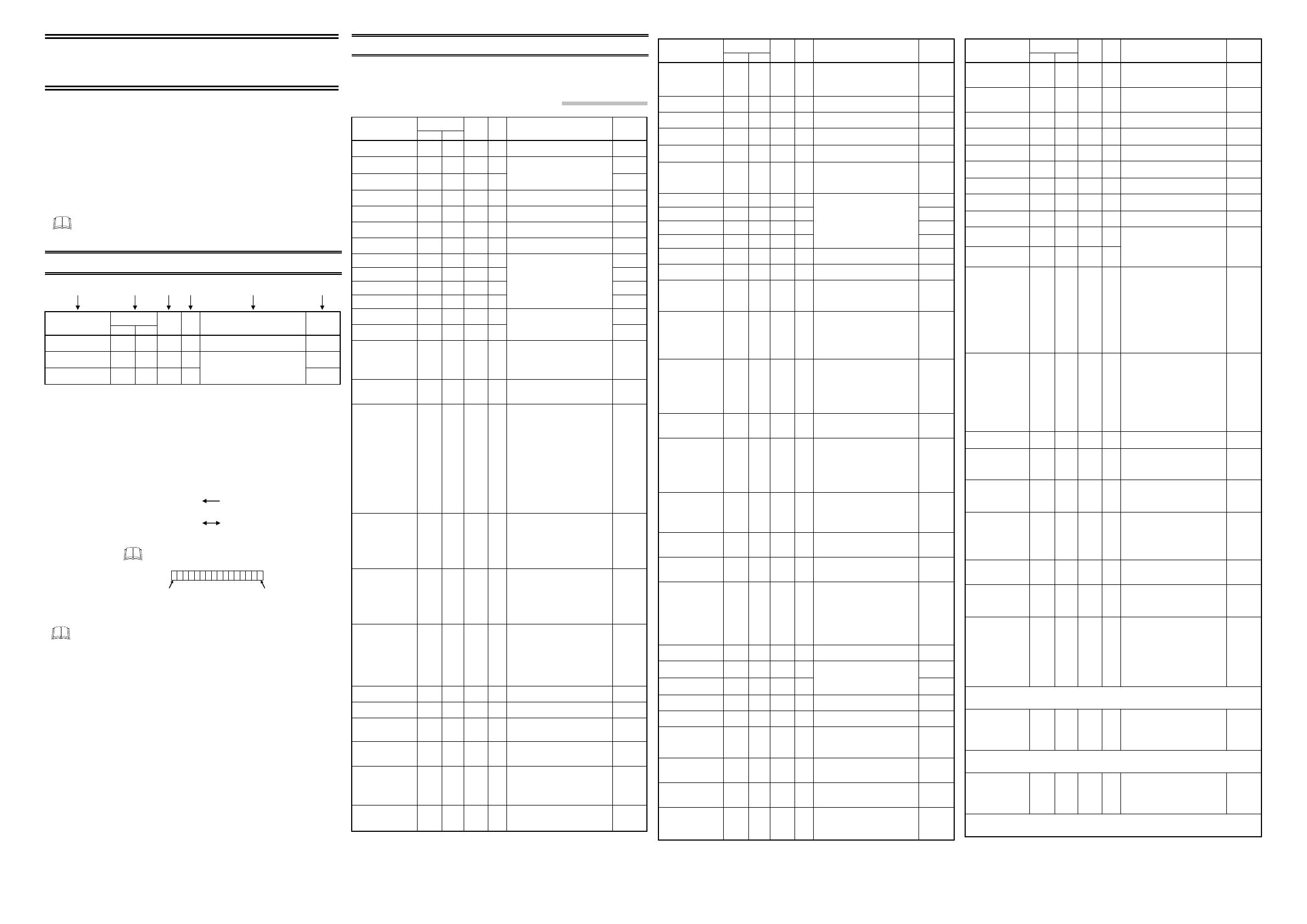
1. REFERENCE TO DATA MAP
Register
address
Name
HEX DEC
Number
of data
Attri-
bute
Data range
Factory set
value
Measured value (PV)
0000 0 31 RO Input scale low to Input scale high ⎯
Current transformer 1
(CT1) input value monitor
0020 32 31 RO ⎯
Current transformer 2
(CT2) input value monitor
0040 64 31 RO
CTL-6-P-N:
0.0 to 30.0A
CTL-12-S56-10L-N:
0.0 to 100.0 A
⎯
(1) Name: Name of communication data
(2) Register address: The head address of each item (Vacant numbers become unused)
HEX: Hexadecimal
DEC: Decimal
(3) Number of data: Number of data points
The address in the register address column will be the head address,
and the number of data items is indicated in this column.
(4) Attribute: RO: Read only data
(Host computer [Client] Controller [Server])
R/W: Read and Write data
(Host computer [Client] Controller [Server])
(5) Data range: Read or write range of communication data
Bit image of bit data is as follows.
Bit 15
Bit 0
…………….……………………
16-bit data
(6) Factory set value: Factory set value of communication data
Reading data of unused setting items are factory set values. Unused setting
items may not be written. To do so will not cause an error however and data will
be rejected.
2. DATA MAP
The data map shows data which can be used for communication between the host computer
[Client] and controller (FB100/400/900) [Server].
2.1 FB100/400/900 Communication Data
Register
address
Name
HEX DEC
Number
of data
Attri-
bute
Data range
Factory set
value
Measured value (PV)
0000 0 31 RO Input scale low to Input scale high ⎯
Current transformer 1
(CT1) input value monitor
0020 32 31 RO ⎯
Current transformer 2
(CT2) input value monitor
0040 64 31 RO
CTL-6-P-N:
0.0 to 30.0A
CTL-12-S56-10L-N:
0.0 to 100.0 A
⎯
Set value (SV) monitor
0060 96 31 RO Setting limiter low to Setting limiter high
⎯
Remote setting (RS)
input value monitor
0080 128 31 RO Setting limiter low to Setting limiter high
⎯
Burnout state monitor 00A0 160 31 RO 0: OFF
1: ON
⎯
Burnout state monitor of
feedback resistance input
00C0 192 31 RO 0: OFF
1: ON
⎯
Event 1 state monitor 00E0 224 31 RO ⎯
Event 2 state monitor 0100 256 31 RO ⎯
Event 3 state monitor 0120 288 31 RO ⎯
Event 4 state monitor 0140 320 31 RO
0: OFF
1: ON
⎯
Heater break alarm 1
(HBA1) state monitor
0160 352 31 RO ⎯
Heater break alarm 2
(HBA2) state monitor
0180 384 31 RO
0: OFF
1: ON
⎯
Manipulated output
value (MV1) monitor
[heat-side]
01A0 416 31 RO PID control or Heat/Cool PID control:
−5.0 to +105.0 %
Position proportioning control with
feedback resistance (FBR) input:
0.0 to 100.0 %
⎯
Manipulated output
value (MV2) monitor
[cool-side]
01C0 448 31 RO −5.0 to +105.0 % ⎯
Error code 01E0 480 31 RO Bit data
Bit 0: Adjustment data error
Bit 1: Back-up error
Bit 2: A/D conversion error
Bit 3 to Bit 4: Unused
Bit 5: Custom data error
Bit 6: Unused
Bit 7: Watchdog timer error
Bit 8: Stack overflow
Bit 9 to Bit 10: Unused
Bit 11: Program error (busy)
Bit 12 to Bit 15: Unused
Data 0: OFF 1: ON
[Decimal number: 0 to 4095]
⎯
Digital input (DI) state
monitor
0200 512 31 RO Bit data
Bit 0: DI1 Bit 4: DI5
Bit 1: DI2 Bit 5: DI6
1
Bit 2: DI3 Bit 6: DI7
1
Bit 3: DI4 Bit 7 to Bit 15: Unused
Data 0: Open 1: Closed
[Decimal number: 0 to 127]
⎯
Output state monitor 0220 544 31 RO Bit data
Bit 0: OUT1 Bit 4: DO3
1
Bit 1: OUT2 Bit 5: DO4
1
Bit 2: DO1 Bit 6 to Bit 15: Unused
Bit 3: DO2
Data 0: OFF 1: ON
[Decimal number: 0 to 63]
⎯
Operation mode state
monitor
0240 576 31 RO Bit data
Bit 0: STOP
Bit 1: RUN
Bit 2: Manual mode
2
Bit 3: Remote mode
2
Bit 4 to Bit 15: Unused
Data 0: OFF 1: ON
[Decimal number: 0 to 15]
⎯
Memory area soak time
monitor
0260 608 31 RO 0 to 11999 seconds or 0 to 5999 minutes ⎯
Integrated operating
time monitor
0280 640 31 RO 0 to 19999 hours ⎯
Holding peak value
ambient temperature
monitor
02A0 672 31 RO −10.0 to +100.0 °C ⎯
Power feed forward
input value monitor
1
02C0 704 31 RO 0.0 to 160.0 %
Display in the percentage of the load
voltage (rated value).
⎯
Backup memory state
monitor
02E0 736 31 RO 0: The content of the backup memory
does not coincide with that of the
RAM.
1: The content of the backup memory
coincides with that of the RAM.
⎯
Unused 0300 768 31 ⎯ ⎯ ⎯
•
•
•
•
•
•
•
•
•
03FF 1023 31
1
Unused on the FB100.
2
During operation in Manual mode, the Manual mode of the Operation mode state monitor is set to the “1: ON” state
and the Remote mode of the same monitor is se to the “0: OFF” state even if the parameter, Remote/Local transfer is
set to “1: Remote mode.”
Register
address
Name
HEX DEC
Number
of data
Attri-
bute
Data range
Factory set
value
PID/AT transfer 0400 1024 31 R/W 0: PID control
1: Autotunig (AT) *
* Automatically reverts to 0 after
Autotuning ends.
0
Auto/Manual transfer 0420 1056 31 R/W 0: Auto mode
1: Manual mode
0
Remote/Local transfer 0440 1088 31 R/W 0: Local mode
1: Remote mode
0
RUN/STOP transfer 0460 1120 31 R/W 0: RUN (control start)
1: STOP (control stop)
0
Memory area transfer
0480 1152 31 R/W 1 to 8 1
Interlock release 04A0 1184 31 R/W 0: Interlock release (Execution/State)
1: Interlock state
“1” is for monitoring the interlocked state.
Under this condition, do not write “1.”
0
Event 1 set value 04C0 1216 31 R/W 50
Event 2 set value 04E0 1248 31 R/W 50
Event 3 set value 0500 1280 31 R/W 50
Event 4 set value 0520 1312 31 R/W
Deviation:
−Input span to +Input span
Process and set value:
Input scale low to Input scale high
Manipulated output value (MV1 or MV2):
−5.0 to +105.0 %
50
Control loop break alarm
(LBA) time
0540 1344 31 R/W 0 to 7200 seconds (0: Unused) 480
LBA deadband
0560 1376 31 R/W 0 to Input span 0
Set value (SV) 0580 1408 31 R/W Setting limiter low to Setting limiter high
TC/RTD
inputs: 0
V/I inputs:
0.0
Proportional band
[heat-side]
05A0 1440 31 R/W TC/RTD inputs:
0 (0.0, 0.00) to Input span
(Unit: °C [°F])
1
Voltage (V)/Current ( I ) inputs:
0.0 to 1000.0 % of Input span
(0, 0.0, 0.00: ON/OFF action)
TC/RTD
inputs: 30
V/I inputs:
30.0
Integral time
[heat-side]
05C0 1472 31 R/W PID control or Heat/Cool PID control:
0 to 3600 seconds or
0.0 to 1999.9 seconds
2
(0, 0.0: PD action)
3
Position proportioning control:
1 to 3600 seconds or
0.1 to 1999.9 seconds
2
240
Derivative time
[heat-side]
05E0 1504 31 R/W 0 to 3600 seconds or
0.0 to 1999.9 seconds
2
(0, 0.0: PI action)
60
Control response
parameter
0600 1536 31 R/W 0: Slow
1: Medium
2: Fast
[When the P or PD action is selected, this
setting becomes invalid.]
PID control,
Position
proportioning
control: 0
Heat/Cool
PID control:
2
Proportional band
[cool-side]
0620 1568 31 R/W TC/RTD inputs:
1 (0.1, 0.01) to Input span
(Unit: °C [°F])
1
Voltage (V)/Current ( I ) inputs:
0.1 to 1000.0 % of Input span
TC/RTD
inputs: 30
V/I inputs:
30.0
Integral time
[cool-side]
0640 1600 31 R/W 0 to 3600 seconds or
0.0 to 1999.9 seconds
2
(0, 0.0: PD action)
3
240
Derivative time
[cool-side]
0660 1632 31 R/W 0 to 3600 seconds or
0.0 to 1999.9 seconds
2
(0, 0.0: PI action)
60
Overlap/Deadband 0680 1664 31 R/W TC/RTD inputs:
−Input span to +Input span
(Unit:°C [°F])
Voltage (V)/Current ( I ) inputs:
−100.0 to +100.0 % of Input span
Minus (−) setting results in Overlap.
However, the overlapping range is within
the proportional range.
0
Manual reset
06A0 1696 31 R/W −100.0 to +100.0 % 0.0
Setting change rate
limiter (up)
06C0 1728 31 R/W 0
Setting change rate
limiter (down)
06E0 1760 31 R/W
0 to Input span/unit time *
(0: Unused)
* Unit time: 60 seconds
(factory set value)
0
Area soak time
0700 1792 31 R/W 0 to 11999 seconds or 0 to 5999 minutes 0:00
Link area number
0720 1824 31 R/W 0 to 8 (0: No link) 0
Heater break alarm 1
(HBA1) set value
0740 1856 31 R/W CTL-6-P-N:
0.0 to 30.0 A (0.0: Unused)
CTL-12-S56-10L-N:
0.0 to 100.0 A (0.0: Unused)
0.0
Heater break
determination point 1
0760 1888 31 R/W 0.0 to 100.0 % of HBA1 set value
(0.0: Heater break determination is
invalid)
30.0
Heater melting
determination point 1
0780 1920 31 R/W 0.0 to 100.0 % of HBA1 set value
(0.0: Heater melting determination is
invalid)
30.0
Heater break alarm 2
(HBA2) set value
07A0 1952 31 R/W CTL-6-P-N:
0.0 to 30.0 A (0.0: Unused)
CTL-12-S56-10L-N:
0.0 to 100.0 A (0.0: Unused)
0.0
1
Varies with the setting of the Decimal point position selection.
2
Varies with the setting of the Integral/Derivative time decimal point position selection.
3
When the heat-side or cool-side integral time is set to zero for Heat/Cool PID control, PD control will take place for
both heat-side and cool-side.
Register
address
Name
HEX DEC
Number
of data
Attri-
bute
Data range
Factory set
value
Heater break
determination point 2
07C0 1984 31 R/W 0.0 to 100.0 % of HBA2 set value
(0.0: Heater break determination is
invalid)
30.0
Heater melting
determination point 2
07E0 2016 31 R/W 0.0 to 100.0 % of HBA2 set value
(0.0: Heater melting determination is
invalid)
30.0
PV bias
0800 2048 31 R/W −Input span to + Input span 0
PV digital filter
0820 2080 31 R/W 0.0 to 100.0 seconds (0.0: Unused) 0.0
PV ratio
0840 2112 31 R/W 0.500 to 1.500 1.000
PV low input cut-off
0860 2144 31 R/W 0.00 to 25.00 % of input span 0.00
RS bias
0880 2176 31 R/W −Input span to + Input span 0
RS digital filter
08A0 2208 31 R/W 0.0 to 100.0 seconds (0.0: Unused) 0.0
RS ratio
08C0 2240 31 R/W 0.001 to 9.999 1.000
Proportional cycle time
[heat-side]
08E0 2272 31 R/W
Proportional cycle time
[cool-side]
0900 2304 31 R/W
0.1 to 100.0 seconds
M: Relay contact output
V: Voltage pulse output
T: Triac output
D: Open collector output
M output:
20.0
V, T, D
output: 2.0
Manual manipulated
output value
0920 2336 31 R/W PID control:
Output limiter low [MV1] to
Output limiter high [MV1]
Heat/cool PID control:
−Output limiter high [MV2] to
+Output limiter high [MV1]
(−105.0 to +105.0 %)
Position proportioning control with
feedback resistance (FBR) input:
Output limiter low [MV1] to
Output limiter high [MV1]
0.0
Set lock level 0940 2368 31 R/W Bit data
Bit 0: Lock only setting items other than
SV and event set value (EV1 to
EV4)
Bit 1: Lock only event set value
(EV1 to EV4)
Bit 2: Lock only set value (SV)
Bit 3 to Bit 15: Unused
Data 0: Unlock 1: Lock
[Decimal number: 0 to 7]
0
STOP display
a
0960 2400 31 R/W 0: SToP is displayed on the PV display
1: SToP is displayed on the SV display
1
Bar graph display
a
0980 2432 31 R/W 0: No display 4: Deviation value
1: MV 5: CT1 input value
2: PV 6: CT2 input value
3: SV monitor
1
Bar graph display
resolution
a
09A0 2464 31 R/W 1 to 100 digit/dot
The resolution can be changed when the
bar graph display was set to deviation
value or CT input value.
100
Direct key 1
a
[FB100]
Direct key selection
09C0 2496 31 R/W [FB100]
0: Unused
1: Used
[FB400/900]
0: Unused
1: A/M transfer key (Type 1, Type 2)
1
Direct key 2
a, b
09E0 2528 31 R/W 0: Unused
1: MONI key (For type 1) or
R/L transfer key (For type 2)
1
Direct key 3
a, b
0A00 2560 31 R/W 0: Unused
1: AREA key (For type 1) or
RUN/STOP transfer key
(For type 2)
1
Direct key type
a
0A20 2592 31 R/W [FB100]
1: Auto/Manual transfer
2: Monitor
3: Memory area transfer
4: Remote/Local transfer
5: RUN/STOP transfer
[FB400/900]
1: Type 1
2: Type 2
1
Engineering mode
For the data, see the COM-JL [For FB100/FB400/FB900] Instruction Manual (IMR01Y10-E).
Startup tuning (ST) 1960 6496 31 R/W 0: Startup tuning (ST) unused
1: Execute once *
2: Execute always
* Automatically reverts to 0 after Startup
tuning (ST) ends.
0
Engineering mode
For the data, see the COM-JL [For FB100/FB400/FB900] Instruction Manual (IMR01Y10-E).
Automatic temperature
rise learning
1A20 6688 31 R/W 0: Unused
1: Learning *
* Automatically reverts to 0 after
automatic temperature rise learning
ends.
1
Engineering mode
For the data, see the COM-JL [For FB100/FB400/FB900] Instruction Manual (IMR01Y10-E).
a
The attribute becomes RO (Only reading data is possible) during RUN (control).
b
Unused on the FB100.
CO
JL
All Rights Reserved, Copyright © 2006, RKC INSTRUMENT INC.
(1) (2) (3) (4) (5) (6)
[For FB100/FB400/FB900]
Communication
Data List


