Home Decorators Collection 118076 User manual
- Category
- Fireplaces
- Type
- User manual

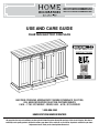
USE AND CARE GUIDE
CHASTAIN ELECTRIC FIREPLACE
1004151498/308824334/28MM90668-PG76
1004151417/308824356/28MM90668-PO98
1004151415/308824412/28MM90668-PD01
We appreciate the trust and condence you have placed in Home Decorators through the purchase of this electric replace. We strive to
continually create quality products designed to enhance your home. Visit us online to see our full line of products available for your home
improvement needs. Thank you for choosing Home Decorators!
THANK YOU
QUESTIONS, PROBLEMS, MISSING PARTS? BEFORE RETURNING TO THE STORE,
CALL HOME DECORATORS COLLECTION CUSTOMER SERVICE
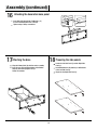
8 A.M. - 7 P.M., EST, MONDAY - FRIDAY, 9 A.M. - 6 P.M., EST, SATURDAY
1-800-986-3460
HOMEDEPOT.COM/HOMEDECORATORS
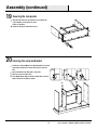
3D INTERACTIVE
INSTRUCTIONS
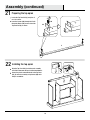
FOR THIS PRODUCT ARE IN

2
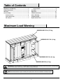
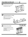
MAXIMUM LOAD 155 lb. (70.3 kg)
MAXIMUM LOAD 20 lb. (9.1 kg)
MAXIMUM LOAD 15 lb. (6.8 kg)
MAXIMUM LOAD 15 lb. (6.8 kg)
CAUTION:
This unit is intended for use only with the products and maximum weights indicated. Use with other products or products heavier
than the maximum weights indicated may result in instability causing possible injury.
NOTE:
Flat Panel TVs with base support should be placed squarely in the center of the stand with no overhang on any side.
Maximum Load Warning ........................................... 2
Safety Information ..................................................... 3
Warranty ..................................................................... 5
Pre-Assembly .............................................................6
Hardware Included ................................................... 6
Product Specications ....................................................... 7
Tools Required ................................................................... 7
Package Contents .............................................................. 8
Assembly .................................................................... 9
Operation .................................................................25
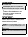
FCC/IC Information ......................................................... 28
Care & Cleaning ....................................................... 28
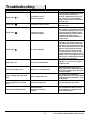
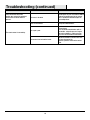
Troubleshooting ....................................................... 29
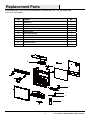
Replacement Parts ..................................................31
Maximum Load Warning
Table of Contents

3
HOMEDEPOT.COM/HOMEDECORATORS
Please contact 1-800-986-3460 for further assistance.
Please read and understand this entire manual before
attempting
to assemble, operate or install the product. If you
have any question regarding the product, please call customer
service at 1-800-986-3460, 8 a.m.-7 p.m., EST, Monday-Friday,
9 a.m. - 6 p.m., EST, Saturday.
When using electrical appliances, basic precautions should
always be followed to reduce the risk of re, electrical shock,
and injury to persons including the following:
1. Read all instructions before using this appliance.
2. If possible, always unplug this appliance when not in use.
3. Only a qualied service person should repair this product.
4. Do not use outdoors.
5.
Do not cover the cord under the carpeting. Do not cover
with throw rugs, runners or the like. Arrange the cord away
from trafc areas and where it will not be tripped over.
6. To disconnect this appliance, turn the controls to the off
position, and then remove the plug from the outlet.
7. Connect to properly grounded outlets only.
8.
This appliance, when installed, must be electrically
grounded in accordance with local codes or, in the
absence of local codes, with the current CSA C22.1
Canadian Electrical Code. For U.S.A. installations, follow
local codes and the National Electrical Code, ANSI/NFPA
NO.70.
9. This appliance has hot and arcing or sparking parts inside.
Do not use it in areas where gasoline, paint or ammable
liquids are used or stored. This replace should not be
used as a drying rack for clothing. Do not hang Christmas
stockings or other decorations on or near this product.
10. There is a thermostat limiter inside the heater. When inner
temperature overheating or abnormal heating occurs, the
thermostat protective device will cut off the power supply
to avoid damage to the replace or risk of re.
Safety Information
WARNING:
Under no circumstances should this replace be
modied. Parts that must be removed for servicing must be
replaced prior to operating this replace again.
DANGER:
High temperatures may be generated under
certain abnormal conditions. Do not partially or fully cover
or obstruct the front of this heater.
WARNING:
If the supply cord is damaged, it must be replaced
by the manufacturer, its service agent or similarly qualified
persons in order to avoid a hazard.
WARNING:
In order to avoid overheating, do not cover the
heater.
WARNING:
Use extreme caution when operating heater
near children and the disabled.
WARNING:
Do not insert or allow foreign objects to enter
any ventilation or exhaust opening as this may cause an electric
shock or re, or damage the appliance.
WARNING:
To prevent a possible re, do not block air intakes
or exhaust in any manner. Do not use on soft surfaces, like a bed,
where the opening may become blocked.
WARNING:
This appliance has hot and arcing or sparking parts
inside. Do not use it in areas where gasoline, paint or ammable
liquids are used or stored. This replace should not be used as a
drying rack for clothing. Do not hang Christmas stockings or other
decorations on or near this product.
WARNING:
Use this appliance only as described in the manual.
Any other use not recommended by the manufacturer may cause
re, electric shock or injury to persons.
WARNING:
This heater is not intended for use in bathrooms,
laundry areas and similar indoor locations. Never locate this
appliance where it may fall into a bathtub or other water container.
WARNING:
This appliance is not a toy. Supervise children
playing near it.
WARNING:
This heater may include a visual alarm to warn
that parts of the heater are getting excessively hot. If the alarm
illuminates, immediately turn the heater off and inspect for any
objects on or adjacent to the heater that may have blocked the
airow or otherwise caused high temperatures to have occurred.
DO NOT OPERATE THE HEATER WITH THE ALARM ILLUMINATING.
CAUTION:
Never leave the heater operating unattended.
Extreme caution is necessary if unsupervised children or invalids
are nearby.
CAUTION:
Before assembly, carefully use scissors or a utility
knife to cut and unwrap all parts. Make sure you do not discard
the hardware.

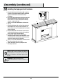
4
NOTE:
To avoid injury from unexpected starting or electrical
shock, do not plug the power cord into a source of power during
unpacking and assembly. The cord must remain unplugged
whenever you are adjusting/assembling the replace.
If any part is missing or damaged, do not attempt to use or
plug in the power cord until the missing or damaged part is
correctly replaced. To avoid electric shock, use only identical
replacement parts when servicing double-insulated tools.
NOTE:
Use care in assembling your new fireplace. Take your
time and use the hardware provided and a quality Phillips head
screwdriver. Never overtighten bolts.
• Do not sit on any part of the mantel.
• It is recommended to work on a soft surface like a rug or to
lay out a blanket to protect the furniture from getting scratched
during the assembly process
NOTE:
SAVE THESE
INSTRUCTIONS
Safety Information (continued)

5
HOMEDEPOT.COM/HOMEDECORATORS
Please contact 1-800-986-3460 for further assistance.
Warranty
1 Year Limited Warranty: The manufacturer warrants that your new Electric Fireplace is free from manufacturing and material defects for
a period of one year from date of purchase, subject to the following conditions and limitations.
1. Install and operate this appliance in accordance with the installation and operating instructions furnished with the
product at all times. Any unauthorized repair, alteration, willful abuse, accident, or misuse of the product shall nullify
this warranty.
2. This warranty is non-transferable, and is made to the original owner, provided that the purchase was made through
an authorized supplier of the product.
3. The warranty is limited to the repair or replacement of part(s) found to be defective in material or workmanship,
provided that such part(s) have been subjected to normal conditions of use and service, after said defect is conrmed
by the manufacturer’s inspection.
4. The manufacturer may, at its discretion, fully discharge all obligations with respect to this warranty by refunding
the wholesale price of the defective part(s).
5. Any installation, labor, construction, transportation, or other related costs/expenses arising from defective part(s),
repair, replacement, or otherwise of same, will not be covered by this warranty, nor shall the manufacturer assume
responsibility for same.
6. The owner/user assumes all other risks, if any, including the risk of any direct, indirect or consequential loss or
damage arising out of the use, or inability to use the product, except as provided by law.
7. All other warranties – expressed or implied – with respect to the product, its components and accessories, or any
obligations/liabilities on the part of the manufacturer are hereby expressly excluded.
8. The manufacturer neither assumes, nor authorizes any third party to assume on its behalf, any other liabilities with
respect to the sale of the product.
9. The warranties as outlined within this document do not apply to non-accessories used in conjunction with the
installation of this product.
10. This warranty gives you specic legal rights, and you may also have other rights which vary from state to state.
This warranty is void if:
a. The replace is subjected to prolonged periods of dampness or condensation.
b. There is any unauthorized alteration, willful abuse, accident, or misuse of the product.
c. You do not have the original receipt of purchase.
Warranty

6
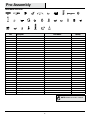
Part Description Part Number Quantity
AA Wood Dowel PH-DWLNTL001 41
BB Cam Lock Screw PH-KDBZNC002 25
CC Cam Lock Connector PH-KDCZNC001 25
DD Shelf Pin PH-SPNPCSPLB2 16
EE Handle with Screws Handle with Screws 2
FF Screw- 3 x 12 mm PH-SCRBLK007 40
GG Screw- 4 x 16 mm PH-SCRBLK019 14
HH Slider PH-BDGBLK001 2
II Screw- 4 x 50 mm PH-SCRBLK006 10
JJ Flat Washer-16 mm PH-WSRBLK002 12
KK Rolling Door Hanger PH-BDRBLK002 4
LL Door Stopper PH-BDSBLK003 2
MM Bolt- 4 x 19 mm Bolt- 4 x 19 mm 2
NN Tipping Restraint Hardware PH-BKTWHT003 1
OO Magnetic Door Latch PH-MTLBLK001 2
PP Right Pin Hinge PH-HNGBLK001 2
QQ Left Pin Hinge PH-HNGBLK001 2
RR Screw- 3.5 x 15 mm PH-SCRBLK015 8
SS Screw- 3 x 15 mm PH-SCRBLK010 12
TT Door Bumper PH-BMPBLK002 2
UU Plastic Connector Block PH-BKTBLK010 2
VV Bolt- 6.3 x 12 mm PH-BLTBLK002 32
WW Plastic Connector Block PH-LVRBLK001 12
XX Bolt- 6.3 x 32 mm PH-BLTBLK001 8
YY Door Bumper PH-BMPCLR001 2
ZZ Leveler (pre-attached) PH-LVRBLK001 4
AAA Insert Mounting Bracket (pre-attached) PH-BKTZNC001 2
BBB Metal Plate (pre-attached) PH-PLTBLK001 4
CCC Floor Glide (pre-attached) PH-GLDBRW001 4
Pre-Assembly
HARDWARE INCLUDED
II JJ
KK
WW
LL
XX
MM
YY
OO
AAA
NN
ZZ
PP
BBB
QQ
CCC
RR SS TT UU VV
DDCC EE FF
GG
HH
AA BB
NOTE:
Hardware not shown to actual size.

7
HOMEDEPOT.COM/HOMEDECORATORS
Please contact 1-800-986-3460 for further assistance.
Phillips Screwdriver
PRODUCT SPECIFICATIONS
VOLTAGE 120VAC, 60 Hz
AMPS 12.5 Amps
WATTS 1500 Watts
PLANNING ASSEMBLY
Before beginning assembly of product, make sure all parts are present. Compare parts with Hardware Included and Package Contents lists.
If any part is missing or damaged, do not attempt to assemble, install or operate the product. Contact customer service for replacement
parts.
Estimated Assembly Time: 90 Minutes
TOOLS REQUIRED
Pre-Assembly (continued)

8
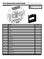
Part Description Quantity
A Bottom Shelf 1
B Right Surround Rail 1
C Left Door 1
D Right Door 1
E Left Partition 1
F Right Partition 1
G Top Panel 1
H Center Shelf 1
I Left Side Panel 1
J Right Side Panel 1
K Top Front Rail 1
L Upper Back Panel 1
M Back Panel 1
N Adjustable Shelf 4
O Left Roller Door 1
P Right Roller Door 1
Q Left Surround Rail 1
R Top Surround Rail 1
S Base Back Rail 1
T Base Left Side Rail 1
U Base Right Side Rail 1
V Base Front Rail 1
W Decorative Base Panel 1
X Fireplace Insert 1
PACKAGE CONTENTS
NOTE:
All panels are labeled left
and right as viewed from the front of
unit.
Pre-Assembly (continued)
X
W
V
T
SC
A
U
D
P
O
Q
E
N
N
M
R
H
L
K
G
M
N
N
F
B
J
I

9
HOMEDEPOT.COM/HOMEDECORATORS
Please contact 1-800-986-3460 for further assistance.
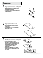
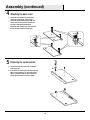
2
Place the Left Partition (E) and Right Partition (F)
on a at surface.
Insert Wood Dowels (AA) into the pre-drilled holes
along the edges as shown.
Preparing the center panels
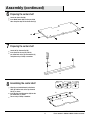
3
Using the Left Surround Rail (Q) and the
Left Partition (E), align the pre-installed dowels and
cam lock screws into the holes.
Secure by inserting Cam Lock Connectors (CC) into
the pre-drilled holes as shown. Use a Phillips
screwdriver to tighten all the Cam Lock
Connectors (CC).
Repeat with the Right Surround Rail (B) and Right
Partition (F) until all Cam Lock Connectors (CC) have
been secured.
Attaching the decorative front panels
1
Locate the Left Surround Rail (Q) and Right Surround
Rail (B) and place on a at surface.
Insert Cam Lock Screws (BB) into the pre-drilled holes
on both panels as shown.
Preparing the decorative front panels
Assembly
F
F
B
CC
Q
E
E
AA
BB
Q
B

10
4
Assembly (continued)
Locate the Left Partition (E) and the Right
Partition (F) and place on a at surface.
Locate the Magnetic Door Catches (OO) and
secure them to each partition using Screws
(SS) where indicated by the diagram.
Locate the Door Bumpers (TT) and secure one
to each partition using the Screws (SS).
Attaching the door catch
F
OO
TT
E
SS
SS
5
Flip the right and left center panel assemblies
from step 4 over.
Insert Cam Lock Screws (BB) into the pre-drilled
holes in each partition (E, F) and secure using a
Phillips screwdriver. Repeat until all Cam Lock
Screws (BB) have been installed as shown.
F
BB
E
Preparing the center panels

11
HOMEDEPOT.COM/HOMEDECORATORS
Please contact 1-800-986-3460 for further assistance.
7
8
6
Assembly (continued)
Locate the Top Surround Rail (R).
Insert Cam Lock Screws (BB) into the
pre-drilled holes in the Top Surround Rail (R)
and tighten using a Phillips screwdriver.
Align the pre-installed dowels in the Center
Shelf (H) with the holes in the Top Surround
Rail (R) as shown.
Insert the Cam Lock Connectors (CC) into the
pre-drilled holes as shown.
Secure using a Phillips screwdriver.
Locate the Center Shelf (H).
Insert Wood Dowels (AA) into the pre-drilled
holes along the edges of the Center Shelf (H).
R
H
R
CC
AA
BB
Preparing the center shelf
Assembling the center shelf
Preparing the center shelf
H

12
HOMEDEPOT.COM/HOMEDECORATORS
Please contact 1-800-986-3460 for further assistance.
1110
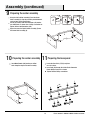
9
Preparing the center assembly Preparing the base panel
Using the Left Partition assembly (E) and the Center
Shelf assembly (H), align the previously installed dowels
and cam lock screws into the holes.
Secure by inserting Cam Lock Connectors (CC) into the
pre-drilled holes as shown. Use a Phillips screwdriver to
tighten all Cam Lock Connectors (CC).
Repeat to secure the Right Partition assembly (F) onto
the Center Shelf assembly (H).
Preparing the center assembly
Assembly (continued)
U
S
V
T
F
H
E
CC
Insert Wood Dowels (AA) into the pre-drilled
holes along the edges of the main assembly.
Locate the Base Rails (S,T,U,V) and place
on a at surface.
Insert Bolts (VV) through the 2-hole Plastic Connector
Blocks (WW) on each rail as shown.
Tighten with the Phillips screwdriver.
AA
WW
V V

13
HOMEDEPOT.COM/HOMEDECORATORS
Please contact 1-800-986-3460 for further assistance.
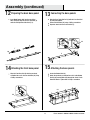
12
14
13
15
Assembly (continued)
S
S
U
T
V
XX
A
AA
V V
XX
Preparing the back base panel
Attaching the front base panel
Connecting the base panels
Attaching the base panels
Insert Wood Dowels (AA) into the pre-drilled
holes along the edges of the Base Back Rail (S)
and Left and Right Base Side Rails (T, U).
Align the Front Base Rail (V) with the previously
assembled base rails. Secure with Bolts (XX) using
a Phillips screwdriver.
Align the Base Right Side Rail (U) with the Base Back Rail
(S) and push together.
Secure with the Bolts (XX) using a Phillips screwdriver.
Repeat to attach the Base Left Side Rail (T).
Locate the Bottom Shelf (A).
Attach the previously assembled base rails to the Bottom
Shelf (A) by inserting Bolts (VV) through the 2-hole Plastic
Connector Blocks. Tighten with a Phillips screwdriver.
U
T

14
16
Assembly (continued)
W
17
Attaching the base
Align the Bottom Shelf (A) with the center assembly.
Insert Screws (II) through the bottom of the Bottom
Shelf (A) and securely tighten using a
Phillips screwdriver.
A
II
18
Locate the Left Side Panel (I) and the Right Side
Panel (J).
Insert Wood Dowels (AA) into the pre-drilled holes
in the Left Side Panel (I).
Repeat for the Right Side Panel (J).
Preparing the side panels
I
J
AA
XX
JJ
Attaching the decorative base panel
Insert Bolts (XX) through the Flat Washers (JJ)
to secure the Decorative Base Panel (W).
Tighten using a Phillips screwdriver.

15
HOMEDEPOT.COM/HOMEDECORATORS
Please contact 1-800-986-3460 for further assistance.
20
19
Find the pre-attached Metal Plate (BBB) behind the surround
and rotate it onto the back of the center shelf to span the
joint.
Secure the Metal Plate (BBB) with a Screw (FF).
Repeat to secure the both sides.
Insert Wood Dowels (AA) into the pre-drilled holes in the top
edge of the main assembly as shown.
Securing the surround bracket
Align the Left Side Panel (I) with the main assembly and
secure together using Screws (II) and a
Phillips screwdriver.
Repeat to attach the Right Side Panel (J).
Securing the side panels
Assembly (continued)
I
J
II
BBB
FF
AA

16
21
22
Locate the Top Front Rail (K) and place it
on a at surface.
Insert the Screws (GG) through the Plastic
Connector Blocks (UU) on each side of the
Top Front Rail (K) as shown.
Preparing the top apron
Align the Top Front Rail (K) with the main assembly
and slide it down onto the pre-installed wood dowels.
Secure the plastic connector blocks to the Top Front
Rail (K) and main assembly using Screws (GG) and a
Phillips screwdriver.
Installing the top apron
Assembly (continued)
K
K
GG
UU
GG

17
HOMEDEPOT.COM/HOMEDECORATORS
Please contact 1-800-986-3460 for further assistance.
Insert Wood Dowels (AA) into the pre-drilled holes
in the top edges of the main assembly.
23
Preparing the top of the assembly
Assembly (continued)
Locate the Top Panel (G) and place onto a at
surface.
Insert the Cam Lock Screws (BB) into the pre-drilled
holes in the bottom of the Top Panel (G).
Tighten using a Phillips Screwdriver.
Place the Top Panel (G) on top of the main assembly
while aligning the previously installed cam lock screws
and wood dowels.
From underneath, insert Cam Lock Connectors (CC) into
the pre-drilled holes.
Tighten using a Phillips Screwdriver.
24
25
Preparing the top panel for assembly
Attaching the top assembly
AA
G
G
CC
BB

18
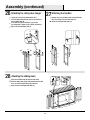
Locate the Left and Right Rolling Doors (O,P).
Place the Rolling Door Hangers (KK) on the outside of
the Left Roller Door (O).
Insert Bolts (VV) with Flat Washers (JJ) into the
pre-drilled holes. Tighten using a Phillips Screwdriver.
Repeat for the Right Roller Door (P).
Align the Left Roller Door (O) with the roller track.
With the Rolling Door Hanger (KK) latched onto the roller
track, push the Left Roller Door (O) to the right.
Repeat to attach the Right Roller Door (P).
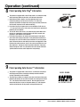
Remove the pre-assembled screws from the Handles
(EE), then attach to the Left Roller Door (O).
Repeat for the Right Roller Door (P).
26
28
27
Attaching the rolling door hanger
Attaching the sliding doors
Attaching the handles
Assembly (continued)
KK
EE
EE
KK
O
P
P
O
P
O
VV
JJ
JJ
VV
KK

19
HOMEDEPOT.COM/HOMEDECORATORS
Please contact 1-800-986-3460 for further assistance.
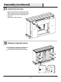
Insert the Bolts (MM) through the roller track to secure
the Door Stoppers (LL).
Place the Door Bumpers (YY) on the inner edge of each
door as indicated. Simply pull off the adhesive and stick.
Insert Screws (GG) through the Sliders (HH) and into the
pre-drilled holes into each Roller Door (O, P).
29
30
Attaching the door stopper
Attaching the track guide
Assembly (continued)
LL
MM
GG
HH
YY
P
O

20
N
N
N
N
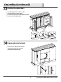
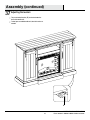
Attach the Upper Back Panel (L) and Side Back Panels
(M) by inserting the Screws (FF) through the pre-drilled
holes in the Upper Back Panel (L) and the Side Back
Panels (M).
Tighten using a Phillips Screwdriver.
31
32
Installing the back panels
Attaching the adjustable shelves
Insert the Shelf Pins (DD) into the pre-drilled holes on
the inside of each side cabinet panel as shown.
Rest the Adjustable Shelf (N) on the Shelf Pins (DD).
Assembly (continued)
FF
DD
M
M
L
Page is loading ...
Page is loading ...
Page is loading ...
Page is loading ...
Page is loading ...
Page is loading ...
Page is loading ...
Page is loading ...
Page is loading ...
Page is loading ...
Page is loading ...
Page is loading ...
-
 1
1
-
 2
2
-
 3
3
-
 4
4
-
 5
5
-
 6
6
-
 7
7
-
 8
8
-
 9
9
-
 10
10
-
 11
11
-
 12
12
-
 13
13
-
 14
14
-
 15
15
-
 16
16
-
 17
17
-
 18
18
-
 19
19
-
 20
20
-
 21
21
-
 22
22
-
 23
23
-
 24
24
-
 25
25
-
 26
26
-
 27
27
-
 28
28
-
 29
29
-
 30
30
-
 31
31
-
 32
32


Home Decorators Collection 118076 User manual
- Category
- Fireplaces
- Type
- User manual
Ask a question and I''ll find the answer in the document
Finding information in a document is now easier with AI
Related papers
-
Home Decorators Collection 118144 User manual
-
-
-
-
-
-
-
-
-


