GE GXMH31H Installation guide

Type
Installation guide

The GE GXMH31H water softener removes dirt and other impurities from your water, providing cleaner, healthier water for your home. It has a 3-gallon per minute flow rate and can handle water pressure up to 125 psi. The softener also features a digital display that shows the remaining salt level, the time until the next regeneration cycle, and any error codes. Plus, the GXMH31H is easy to install and maintain, with a simple bypass valve for easy servicing.

The GE GXMH31H water softener removes dirt and other impurities from your water, providing cleaner, healthier water for your home. It has a 3-gallon per minute flow rate and can handle water pressure up to 125 psi. The softener also features a digital display that shows the remaining salt level, the time until the next regeneration cycle, and any error codes. Plus, the GXMH31H is easy to install and maintain, with a simple bypass valve for easy servicing.

Before you start.
BEFORE YOU START
The water softener requires a minimum water flow of 3 gallons per minute at the inlet. Maximum
allowable inlet water pressure is 125 psi. If daytime pressure is over 80 psi, nighttime pressure may
exceed the maximum. Use a pressure reducing valve if necessary (Adding a pressure reducing valve
may reduce the flow). If your home is equipped with a back flow preventer, an expansion tank must
be installed in accordance with local codes and laws.
The water softener uses a direct plug-in external power supply (included). Be sure to use the included
power supply and plug it into a nominal 120V, 60 cycle household outlet that is in a dry location only,
grounded and properly protected by an over current device such as a circuit breaker or fuse.
Do not use this system to treat water that is microbiologically unsafe or of unknown quality without
adequate disinfection upstream or downstream of the system.
Ground Clamp
Kit
Bypass Valve 12 ft.
Drain Hose
Clips
Installation
Adaptors
Hose Clamps Overflow
Adapter
Grommet O-rings
WARNING! Discard all unused parts and packaging material after installation. Small parts
remaining after the installation could be a choke hazard.
8
Pliers
Screwdriver
Teflon tape
Razor knife
Two adjustable wrenches
Additional tools may be required if modification
to home plumbing is necessary.
TOOLS AND MATERIALS REQUIRED FOR INSTALLATION
NOTE: Failure to comply with these installation instructions will void the product warranty, and the
installer will be responsible for any service, repair or damages caused thereby.
Silicone
Grease
INSPECT SHIPMENT
The parts required to assemble and install the water softener are included with the unit. Thoroughly
check the water softener for possible shipping damage and parts loss. Also inspect and note any damage
to the shipping carton.
Remove and discard (or recycle) all packing materials. To avoid loss of small parts, we suggest you keep the
small parts in the parts bag until you are ready to use them.
9
Installation Requirements.
PROPER ORDER TO INSTALL WATER TREATMENT EQUIPMENT
Well
Pump
Well Water Supply
City Water Supply
OR
Pressure
Tank
Optional
Sediment
Filter
Water
Heater
Water
Softener
Hot Water to House
Cold Water to House
Untreated Water to
Outside Faucets
LOCATION REQUIREMENTS
Consider all of the following when selecting an
installation location for the water softener.
Do not locate the water softener where freezing
temperatures occur. Do not attempt to treat
water over 120ºF. Freezing temperatures or
hot water damage voids the warranty.
To condition all water in the home, install
the water softener close to the water supply
inlet, and upstream of all other plumbing
connections, except outside water pipes.
Outside faucets should remain on hard water to
avoid wasting conditioned water and salt.
A nearby drain is needed to carry away
regeneration discharge (drain) water. Use a
floor drain,laundry tub, sump, standpipe, or
other options(check your local codes). See
“Air Gap Requirements” and “Valve Drain
Requirements”sections.
The water softener uses a direct plug-in
external power supply (included). Be sure to
use the included power supply and plug it into
a nominal 120V, 60 cycle household outlet that
is in a dry location only, grounded and properly
protected by an over current device such as a
circuit breaker or fuse.
Always install the water softener between
the water inlet and water heater. Any other
installed water conditioning equipment should
be installed between the water inlet and water
softener (See Figure below).
If installing the water softener outdoors, do
not locate where it will be exposed to wet
weather, direct sunlight, extreme hot or cold
temperatures, or other forms of abuse.
DO NOT RUN HOT WATER THROUGH THE
SOFTENER. Temperature of water passing
through the softener must be less than 120° F.
Avoid installing in direct sunlight. Excessive sun
heat may cause distortion or other damage to
non-metallic parts.
When installing in an outside location you
must take steps necessary to assure the
softener, installation plumbing and wiring, are
protected from the elements, direct sunlight,
contaminantion, vandalism, insects, vermin, etc.
Do not install the softener where it would block
access to the water heater or access to the
main water shutoff.
DIMENSIONS
IN
OUT
3-3/4"
TOP VIEW
FRONT VIEW SIDE VIEW
14-7/16"
22-7/16"
47-5/8"
41-1/2"
IN - OUT
Shut off
valve
10
Installation Requirements.
PLUMBING CODES
All plumbing must be completed in accordance
with national, state and local plumbing codes.
In the state of Massachusetts: The Commonwealth
of Massachusetts plumbing code 248-CMR shall be
adhered to. A licensed plumber shall be used for
this installation.
AIR GAP REQUIREMENTS
A drain is needed for regeneration water (See
Figure 1). A floor drain, close to the water
softener, is preferred. A laundry tub, standpipe,
etc. are other drain options. Secure valve drain
hose in place. Leave an air gap of 1-1/2” between
the end of the hose and the drain. This gap is
needed to prevent back flow of sewer water into
the water softener. Do not put the end of the
drain hose into the drain.
VALVE DRAIN REQUIREMENTS
Using the flexible drain hose (included) (see Figure
2), measure and cut to the length needed. Flexible
drain hose is not allowed in all localities (check
your plumbing codes). If local codes do not allow
use of a flexible drain hose, a rigid valve drain run
must be used. Purchase a compression fitting (1/4
NPT x 1/2 in. minimum tube) and 1/2” tubing from
your local hardware store. Plumb a rigid drain as
needed (see Figure 3).
NOTE: Avoid drain hose runs longer than 30 feet.
Avoid elevating the hose more than 8 feet above
the floor. Make the valve drain line as short and
direct as possible.
FLEXIBLE DRAIN LINE
RIGID DRAIN LINE
FLOOR DRAIN STANDPIPE LAUNDRY TUB
1-1/2”
air gap
1-1/2”
air gap
1-1/2”
air gap
Drain
Hose
Drain
Hose
Drain
Hose
Figure 1
Figure 3
Clip
1/4s NPT thread
1/2s outside
diameter
copper tube (not
provided)
Compression fitting
1/4 NPT x 1/2s O.D
tube (not provided)
Cut barbs from valve drain
elbow (pull clip and remove
drain valve elbow from valve)
Barbs
Barbs for 3/8
s
I.D. tubing
Hose clamp
Drain hose
1/4” NPT Thread
Figure 2
Drain hose adapter
11
Installation Requirements.
INLET/OUTLET PLUMBING REQUIREMENTS
Always install either a single bypass valve
(provided),as shown in Figure 4, or, if desired, parts
for a 3 valve bypass system (not included) can be
purchased and assembled, as shown in Figure 5.
Bypass valves allow you to turn off water to the
softener for maintenance if needed, but still have
water in house pipes.
Pipe fittings must be 1/2” minimum.
Use:
&RSSHUSLSH
7KUHDGHGSLSH
3(;&URVVOLQNHG3RO\HWK\OHQHSLSH
&39&SODVWLFSLSH
2WKHUSLSHDSSURYHGIRUXVHZLWKSRWDEOHZDWHU
IMPORTANT: Do not solder with plumbing
attached to installation adaptors and single
bypass valve. Soldering heat will damage the
adaptors and valve.
DANGER:
Electric Shock Hazard:
Install metal ground clamp to metal house
water supply pipe before beginning
installation. Securely tighten connection in
center of metal ground clamp. Failure to do
so can result in death or electric shock.
3-VALVE BYPASS SYSTEM
For soft water service: Open the inlet and outlet
valves and close the bypass valve.
To bypass the softener and send hard water to
the home: Close the inlet and outlet valves and
open the bypass valve.
3 VALVE BYPASS
Bypass
Valve
Outlet
Valve
Inlet
Valve
From Water
Softener
To Water
Softener
Figure 5
SINGLE BYPASS VALVE
Pull out for “Service”
(Soft water)
Push in for
“Bypass”
Figure 4
Installation
adaptors
12
Installation Instructions.
TYPICAL INSTALLATION
Clips
Inlet
Outlet
Lubricated
O-ring
Single Bypass
Valve
O-ring
1” NPT
Threaded
Adaptor
1” NPT Sweat
Adaptor (not
included)
Pipe
Ground
Clamp
1-1/2”
air gap
Floor Drain
Secure Valve Drain Hose
in place over Floor Drain
Brine Tank
Overflow Hose*
Overflow
Adapter
Ground Clamp
Conditioned
Water
Main Water Pipe
Bypass Valve
Assembly
Plug-in
Transformer
To
Controller
Drain Hose
Adapter
Valve Drain
Hose*
*Do not connect the water
softener valve drain hose to the
brine tank overflow
NOTE: See “Air Gap Requirements” section.
Figure 8
NOTE: Be sure the turbine and support are firmly in place in the
valve outlet. Blow into the valve port and observe the turbine
for free rotation.
5HPRYHSODVWLFVKLSSLQJSOXJDQGZLUHIURPYDOYHRXWOHW
Figure 6
Figure 7
Incoming-
Hard Water
Hard Water
to Outside
Faucets
Top
Cover
Brine Tank
(Salt Storage)
Clips
Turbine
Valve outlet
Turbine shaft and support
Plastic shipping plug
Installation Instructions.
TURN OFF WATER SUPPLY
1. Close the main water supply valve, located near
the well pump or water meter.
2. Open all faucets to drain all water from house
pipes.
NOTE: Be sure not to drain water from the water
heater, as damage to the water heater elements
could result.
INSTALL THE BRINE TANK OVERFLOW
ADAPTER
Install the brine tank overflow grommet and
adapter in the 13/16” diameter hole in the back of
the salt storage tank sidewall, (see Figure 9).
NOTE: The brine tank overflow adapter accepts
either 1/2” or 3/8” I.D. hose.
INSTALL THE BYPASS VALVE
NOTE: For easier installation, remove the top
cover. Release 2 clips at rear of cover. Rotate
cover forward and lift up.
1. Remove two clips from the water softener valve
inlet and outlet ports and visually check and
remove any debris, (see Figure 7).
2. Make sure the turbine assembly spins freely in
the”out” port of the valve, (see Figure 8).
3. If not already done, put a light coating of
silicone grease (provided) on the single bypass
valve o-rings, (see Figure 7).
4. Push the single bypass valve into the softener
valve as far as it will go. Snap the two large
holding clips into place, from the top down, (see
Figure 7 and 10).
IMPORTANT: Be sure the clips snap firmly into
place so the single bypass valve will not pull out.
MOVE THE WATER SOFTENER INTO PLACE
WARNING!
Excessive Weight Hazard
Use two or more people to move and install
water Softener Failure to do so can result
in back or other injury.
1. Move the water softener into the desired
location. Set it on a solid, level surface.
IMPORTANT: Do not place shims directly under
the salt storage tank to level the softener. The
weight of the tank, when full of water and salt,
may cause the tank to fracture at the shim.
CORRECT ASSEMBLY
Outside diameter of
clip channel on single
bypass valve
Clip
Outside diameter of
water softener valve
inlet & outlet
NOTE: Be sure all 3 tabs of the clip go through the match-
ing holes on the water softener valve inlet or outlet, and
fully into the channel on the single bypass valve. Make sure
that the tabs are fully seated.
Figure 10
SINGLE BYPASS VALVE
If connecting to floor
level plumbing, install
the bypass valve turned
downward, as shown.
Salt
Cover
Brinewell
Cover
Brine
Tank
Stand
Tube
Float Stem
Brinewell
Brine
Tubing
Brine Tank
Overflow
Adapter
Grommet
Hole
Nut - Ferrule
Nozzle Venturi
Assembly
Figure 9
Note: Unit is shown with top cover removed.
Brine
Valve
Assembly
13
14
Installation Instructions.
COMPLETE INLET AND OUTLET PLUMBING
WARNING!
ELECTRICAL SHOCK HAZARD:
Install metal ground clamp to metal house
water supply pipe before beginning installation.
Securely tighten connection in center of metal
ground clamp. Failure to do so can result in
death or electrical shock.
6HFXUHJURXQGFODPSWRPHWDOSLSHV
Measure, cut, and loosely assemble pipe and
fittings from the main water pipe to the inlet and
outlet ports of the water softener valve. Be sure
to keep fittings fully together, and pipes squared
and straight. BE SURE INCOMING HARD WATER
SUPPLY IS DIRECTED TO THE SOFTENER VALVE
INLET PORT.
NOTE: Inlet and outlet are marked on the water
softener valve. Trace the water flow direction to
be sure hard water is to inlet.
IMPORTANT: Be sure to fit, align and support
all plumbing to prevent putting stress on the
water softener valve inlet and outlet. Stress from
misaligned or unsupported plumbing may cause
damage to the valve.
,IPDNLQJDVROGHUHGFRSSHULQVWDOODWLRQGRDOO
sweat soldering before connecting pipes to the
NPT adapters and bypass valve. Torch heat will
damage plastic parts.
WARNING!
If solder is used to make pipe connection
use only lead free solder and flux to
prevent lead poisoning.
:KHQWXUQLQJWKUHDGHGSLSHILWWLQJVRQWRSODVWLF
fittings, use care not to cross-thread.
8VH7HIORQ7DSHRQDOOH[WHUQDOSLSHWKUHDGV
Complete the inlet and outlet plumbing for the
type of pipe you will be using. Secure ground
clamp to metal pipes.
INSTALL VALVE DRAIN HOSE
1. Measure and connect the 3/8”drain line
(provided) to the water softener valve drain
fitting. Use a hose clamp to hold the hose in
place.
NOTE: Avoid drain hose runs longer than 30 feet.
Avoid elevating the hose more than 8 feet above
the floor. Make the valve drain line as short and
direct as possible.
IMPORTANT: If codes require a rigid drain line see
“Valve Drain requirements” section.
2. Route the drain hose or copper tubing to the
floor drain or other suitable drain point. Secure
drain hose. This will prevent “whipping’’ during
regenerations. See “Air Gap Requirements”
section (Figure 1).
3. Cut and secure the hose.
NOTE: The softener will not work if the water
cannot exit the drain hose during recharge.
INSTALL BRINE TANK (SALT STORAGE)
OVERFlOW HOSE
1. Measure, cut to needed length and connect the
3/8”drain line (provided) to the salt storage tank
overflow elbow and secure in place with a hose
clamp.
2. Route the hose to the floor drain, or other
suitable drain point no higher than the drain
fitting on the salt storage tank (This is a gravity
drain). If the tank overfills with water, the
excess water flows to the drain point. Cut the
drain line to the desired length and route it
neatly out of the way.
IMPORTANT: For proper operation of the water
softener, do not connect the water softener valve
drain tubing to the salt storage tank overflow hose.
Ground
Clamp
Ground
Clamp
Figure 11
15
Installation Instructions.
RINSE OUT CARBON FINES
Small particles of carbon filtration material are
generated during manufacturing and shipping.
These particles will exit the media tank with the
first water that flows through the softener. These
carbon “fines” are not harmful, but give the water
a gray color and should be rinsed down the drain
before any water from the softener is directed to
the home’s faucets or water heater.
CAUTION: To avoid water or air pressure damage
to softener inner parts, and to flush carbon fines,
pipe chips or other residue from the water pipes,
be sure to do the following steps exactly as
instructed.
1. Make sure the softener’s valve drain hose is
hooked up and the open end directed to a floor
drain, laundry tube or other suitable type of
drain.
2. The system should be connected to electrical
power.
3. Place the bypass valve in “bypass” position
(see Figure 4). On a single valve, slide the stem
inward to bypass. On a 3-valve bypass, close
the inlet and outlet valves and open the bypass
valve.
4. Fully open the house main water pipe shutoff
valve.
5. Initiate a regeneration by pressing and holding
for 3 seconds the RECHARGE button. The valve
motor will start running and the valve will
advance to the “Fill” position (see Figure 21).
6. After you hear the valve motor stop running
(valve in “Fill” position), press, but do not hold
the RECHARGE button. The valve will advance
to the “Brine” position (see Figure 21).
7. After you hear the valve motor stop running
(valve in “Brine” position), press, but do not hold
the RECHARGE button. The valve will advance
to the “Backwash” position (see Figure 21).
8. Once the unit is in the backwash, place bypass
valve in SERVICE position (see Figure 4), exactly
as follows:
(a). Single Bypass Valve: Slowly, slide pull the
valve stem outward toward service, pausing
several times to allow the softener to pressurize
gradually. Check for leaks.
(b). 3-Valve Bypass: Fully close the bypass
valve and open the outlet valve. Slowly open
the inlet valve, pausing several time to allow
the softener to pressurize gradually. Check for
leaks.
9. Let the softener complete the backwash and
fast rinse cycles (takes about 20 minutes).
When the regeneration ends, the softener’s
valve returns to the service position.
TEST FOR LEAKS
To prevent air pressure in the water softener and
plumbing system, complete the following steps in
order:
1. Fully open two or more softened cold water
faucets close to the water softener, located
down stream from the water softener.
2. Observe steady water flow from both open
faucets.
3. After about three minutes, open a hot water
faucet until there is a steady flow and there are
no air bubbles, then close this faucet.
4. Close all cold water faucets and check for leaks
at the plumbing connections that you made.
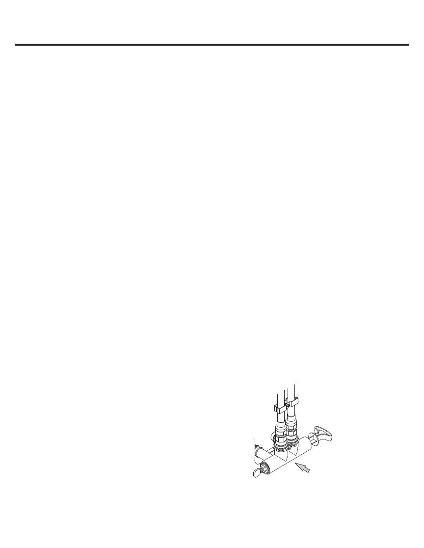
5. Check for leaks around clips at softener’s
inlet and outlet. If a leak occurs at a clip,
depressurize the plumbing (turn off the water
supply and open faucets) before removing clip.
When removing clips at the softener’s inlet
or outlet, push the single bypass valve body
toward the softener (see Figure 14). Improper
removal may damage clips. Do not reinstall
damaged clips.
NOTE: If this procedure is performed on a new
softener, water coming from the taps may
initially be discolored. This normally occurs
the first time water runs through the resin bed.
The discoloration will not last more than a few
minutes.
Figure 14
....depressurize the
plumbing, then push
Bypass Valve body
toward softener
If removing
clips.....
16
Installation Instructions.
ADD WATER AND SALT TO THE SALT
STORAGE TANK
WARNING!
EXCESSIVE WEIGHT HAZARD:
Use two or more people to move and lift
salt bags. Failure to do so can result in
back or other injuries.
1. Using a container, add about three gallons of
clean water into the salt storage tank.
2. Add salt to the storage tank. Use nugget,
pellet or coarse solar salts with less than 1%
impurities.
PLUG IN THE WATER SOFTENER
1. Plug the water softener into an electrical outlet
that is not controlled by a switch.
2. Replace the top cover.
3. Replace the salt hole cover.
NOTE: The water heater is filled with hard
water and, as hot water is used, it will refill with
conditioned water. In a few days, the hot water
will be fully conditioned. To have fully conditioned
hot water immediately, wait until the initial
recharge is over. Then, drain the water heater
(following instructions for water heater) until water
runs cold.
SANITIZE THE WATER SOFTENER / SANITIZE
AFTER SERVICE
1. Open salt hole cover, remove the brinewell cover
and pour about 3 oz. (6 tablespoons) of household
bleach into the softener brinewell. Replace the
brinewell cover.
2. Make sure the bypass valve(s) is in the “service”
(open) position.
3. Start a recharge (regeneration). See “Start a
Recharge” section on page 19.
4. After the recharge has completed, fully open a
cold water faucet, downstream from the softener,
and allow 50 gallons of water to pass through
the system. This should take at least 20 minutes.
Close the faucet.
WARNING! Discard all unused parts
and packaging material after installation.
Small parts remaining after the installation
could be a choke hazard.
32
Exploded View.
8
7
6
5
11
16
146
28
5
999
29
4
12
2
13
3
7
8
9
10
56
56
17
19
20
22
23
23
24
30
6
26
NEW
3333
Exploded View.
Cross-section
View
Seal
Wear Strip
124
109
110
111
112
113
114
116
115
117
118 120
119
146
101
103
105
130
107
108
130
121
148
152
122
123
130
130
132
136
137
138
139
140
141
145
143
152
151
125
148
106
34
Parts List.
REF. NO. GE PART NO. PART DESCRIPTION (01)
 :6; BACK COVER, ELECTRONICS 1
 :6; 25,1*6($/.,7 
 :6; '(&$/)$&(3/$7( 
 :6; +26('5$,1)7 
 :6; ),/7(56&5((1 
 :6; ',675,%8725723 
 :6; ',675,%8725%27720 
0009 :6; RESIN, 1-CU. FT. 1
NEW NEW ACTIVATED CARBON 1
 :6; 7$1.5(6,1;
 :6; &29(5723 
0012 NEW FACEPLATE 1
 :6; &21752/ 
 :6; (;7(51$/32:(56833/<
WITH POWER CORD 1
 :6; &29(56$/7+2/(
WITH LABELS 1
0019 NEW RIM 1
 :6; &29(5%5,1(:(// 
0022 :6; BRINEWELL 1
0023 :6; 6&5(:.,7%5,1(7$1. 1
 :6; 7$1.%5,1( 
0026 :6; 29(5)/2:$'$37(5.,7 1
 :6; *5281'&/$03.,7 
 :6; %5,1(9$/9($60 
 :6; )/2$767(0*8,'( 
 :6; 7$1.1(&.&/$03.,7 1
 :6; 6&5(:;µ 2
 :6; 6:,7&+ 
 :6; 6&5(:;µ 8
 :6; &29(59$/9( 
 :6; WASHER WAVE 1
 :6; 52725',6&$60 
0109 :6; &$3
1
 :6; 6($/25,1*; 1
G
X
M
H
3
1
H
35
Parts List.
REF. NO. GE PART NO. PART DESCRIPTION (01)
 :6; 68332576&5((1 
 :6; 6&5((1 
 :6; )/2:3/8**30 1
0114 :6; GASKET, NOZZLE/VENT 1
0115 :6; CONE SCREEN 1
 :6; 3/8*),//)/2:*30 
 :6; NUT FERRULE 1
 :6; 12==/(9(1785,%2'< 
 :6; 5(7$,1(5 
 :6; 6($/25,1*s;s 2
 :6; %2'<9$/9( 
 :6; 635,1* 
0123 :6; PLUG, DRAIN SEAL 1
0124 :6; NOZZLE/VENTURI ASM. 1
 :6; :$9(635,1*%($5,1* 
 :6; SEAL KIT
1
0132 :6; '5$,1+26($'$37(5.,7 1
 :6; &$0*($5 
 :6; %($5,1* 
 :6; PLATE, MOTOR 1
 :6; 6&5(:;s 3
 :6; 02725$60 
 :6; 6&5(:;s 2
 :6; $'$37(5²1377+5($'²s VALVE 2
 :6; &/,3 
 :6; HARNESS WIRE, SENSOR ASSY 1
0148 :6; 785%,1(6833257$66(0%/< 1
0151 :6; BYPASS ASM. 1
 :6; 6($/25,1* 
0998 :6; INSTALLATION KIT 1
0999 49-50295 OWNER’S MANUAL 1
G
X
M
H
3
1
H
* Includes 2 each of REF. NO. 145 (CLIP) & REF. NO. 152 (O-RING)
  • Page 1 1
  • Page 2 2
  • Page 3 3
  • Page 4 4
  • Page 5 5
  • Page 6 6
  • Page 7 7
  • Page 8 8
  • Page 9 9
  • Page 10 10
  • Page 11 11
  • Page 12 12
  • Page 13 13

GE GXMH31H Installation guide

Type
Installation guide

The GE GXMH31H water softener removes dirt and other impurities from your water, providing cleaner, healthier water for your home. It has a 3-gallon per minute flow rate and can handle water pressure up to 125 psi. The softener also features a digital display that shows the remaining salt level, the time until the next regeneration cycle, and any error codes. Plus, the GXMH31H is easy to install and maintain, with a simple bypass valve for easy servicing.

Ask a question and I''ll find the answer in the document

Finding information in a document is now easier with AI