Page is loading ...

1
Instruction Manual
HI 221 HI 223
pH/mV/ºC
Bench Meters
with Calibration Check
www.hannainst.com
Manufacturer since 1978
Functions
pH Calibration
HI 223 Calibration Check
Microprocessor pH Meter
Confirm
2
Buffer
nd
CFM
Select 2
Buffer
nd
/
Confirm
1 Buffer
st
CFM
/
Select 1
Buffer
st
Start Calibration
CAL
CFM
/GLP
Show GLP Information
Set Instrument Parameters
Clear Log/Cal Information
SET/CLR
RCL
Recall Log Information
LOG
Store Log Information
Select pH/ORP
RANGE
RCL
LOG
CLR
SET
C
C
RANGE
GLP
CFM
CAL
C
ATC
pH
SLOW
FAST
POOR
GOOD

2
TABLE OF CONTENTS
WARRANTY ................................................................................................................... 2
PRELIMINARY EXAMINATION ........................................................................................... 3
GENERAL DESCRIPTION.................................................................................................... 3
FUNCTIONAL DESCRIPTION ............................................................................................. 4
HI 221 SPECIFICATIONS .................................................................................................. 5
HI 223 SPECIFICATIONS ................................................................................................... 6
OPERATIONAL GUIDE ....................................................................................................... 7
pH CALIBRATION ................................................................................................................ 9
ENHANCED CALIBRATION MESSAGES ....................................................................12
ELECTRODE CONDITION AND RESPONSE TIME ............................................................14
GOOD LABORATORY PRACTICE (GLP) .........................................................................15
LOGGING .........................................................................................................................18
SETUP ............................................................................................................................ 22
TEMPERATURE CALIBRATION (FOR TECHNICAL PERSONNEL ONLY) .............................. 25
mV CALIBRATION (FOR TECHNICAL PERSONNEL ONLY) .................................................. 27
PC INTERFACE ............................................................................................................... 28
pH VALUES AT DIFFERENT TEMPERATURES .................................................................... 30
ELECTRODE CONDITIONING & MAINTENANCE .............................................................. 31
TROUBLESHOOTING GUIDE .......................................................................................... 33
TEMPERATURE CORRELATION FOR pH SENSITIVE GLASS ............................................34
ACCESSORIES ................................................................................................................ 36
RECOMMENDATIONS FOR USERS ..................................................................................... 39
WARRANTY
HI 221 and HI 223 are guaranteed for two years against defects in workman-
ship and materials when used for their intended purpose and maintained
according to instructions. The electrodes and the probes are guaranteed for a
period of six months. This warranty is limited to repair or replacement free of
charge.
Damage due to accidents, misuse, tampering or lack of prescribed mainte-
nance are not covered.
If service is required, contact the dealer from whom you purchased the
instrument. If under warranty, report the model number, date of purchase,
serial number and the nature of the problem. If the repair is not covered by
the warranty, you will be notified of the charges incurred. If the instrument is
to be returned to Hanna Instruments, first obtain a Returned Goods Authori-
zation number from the Technical Service department and then send it with
shipping costs prepaid. When shipping any instrument, make sure it is
properly packaged for complete protection.
Dear Customer,
Thank you for choosing a Hanna Instruments product.
Please read this instruction manual carefully before using the instrument.
This manual will provide you with the necessary information for correct use of
the instrument, as well as a precise idea of its versatility.
If you need additional technical information, do not hesitate to e-mail us at
[email protected] or turn to the back cover for our worldwide contact list.
These instruments are in compliance with directives.

3
PRELIMINARY EXAMINATION
Remove the instrument from the packing material and examine it carefully to
make sure that no damage has occurred during shipping. If there is any
damage, notify your Dealer or the nearest Hanna Customer Service Center.
Each instrument is supplied complete with:
HI 1131P Glass-body Combination pH Electrode with 1 m (3.3 ) cable
HI 7669/2W Temperature Probe
HI 76404 Electrode Holder
pH 4.01 & 7.01 Buffer Solutions (20 mL each)
HI 7071S Electrolyte Solution
12 VDC Power Adapter
Instruction Manual
Note: Save all packing material until you are sure that the instrument
functions correctly. All defective items must be returned in the original
packing with the supplied accessories.
GENERAL DESCRIPTION
HI 221 and HI 223 are logging microprocessor-based pH/ORP/temperature
bench meters with Calibration Check.
Calibration Check performs a set of diagnostic tests during calibration using the
history of electrode slope and offset to detect problems that can cause loss of
accuracy.
Calibration Check Features are:
Enhanced Calibration Messages
During calibration the user is warned if one or more parameters are not suitable
to perform an accurate calibration.
Electrode Condition on LCD Display
Determined from the electrode offset and slope.
Electrode response time on LCD Display
Determined from electrode performance during calibration.
Calibration Alarm Time Out
Can be programmed from 1 to 7 days or can be disabled.
Other features include:
One or two point calibration with seven memorized buffers (1.68, 4.01, 6.86,
7.01, 9.18, 10.01 and 12.45 pH), logging up to 100 samples (for HI 221)
and 500 samples (for HI 223), last calibration date and data (GLP), pH
reading with manual or automatic temperature compensation and PC software
interface.

4
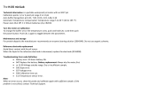
FUNCTIONAL DESCRIPTION
1) Liquid Crystal Display (LCD).
2) CFM / GLP key, to confirm different values or to display Good Laboratory
Practice information.
3) CAL key, to enter and exit/escape the calibration mode.
4) / ºC key, to manually decrease temperature, or other parameters.
5) / ºC key, to manually increase temperature, or other parameters.
6) RCL key, to enter or exit the recall mode.
7) LOG key, to store measured data.
8) RANGE key, to select the measurement range or to switch the focused data.
9) SET / CLR key, to enter the Setup mode or clear calibration history.
10) ON / OFF switch.
11) Power supply socket.
12) BNC electrode connector.
13) Pin input socket.
14) Temperature probe socket.
15) RS232 serial communication connector.
Note: Pin input socket cannot be used as a reference input for electrodes with
separate reference.
Functions pH Calibration
HI 223 Calibration Check
Microprocessor pH Meter
Confirm 2 Buffer
nd
CFM
Select 2 Buffer
nd
/
Confirm 1 Buffer
st
CFM
/
Select 1 Buffer
st
Start Calibration
CAL
CFM/GLP
Show GLP Information
Set Instrument Parameters
Clear Log/Cal Information
SET/CLR
RCL
Recall Log Information
LOG
Store Log Information
Select pH/ORP
RANGE
RCL
LOG
CLR
SET
CC
RANGE
GLP
CFM
CAL
Front Panel
Front Panel
Primary LCD
Secondary LCD
C
ATC
pH
SLOW
FAST
POOR GOOD
1
8
3
2
7
4
6
5
10
9
Electrode
Condition
Electrode
Response
POWER
12VDC
INPUT TEMP
11
12
13
14
Rear Panel
Rear Panel
RS232
15
Front Panel
Rear Panel

5
HI 221
SPECIFICATIONS
egnaR
Hp00.61ot00.2
Vm9.996±
Vm0002±
C°0.021ot0.02
noituloseR
Hp10.0
)Vm9.996±(Vm1.0
)Vm0002±(Vm1
C°1.0
ycaruccA
F°86/C°02@
Hp10.0±
)Vm9.996±(Vm2.0±
)Vm0002±(Vm1±
C°4.0±
kcehCnoitarbilaCseY
ecafretnIretupmoC232SRdetalosi-otpO
noitarbilaCHp
elbaliavasreffub7,tniop2ro1
)54.21,10.01,81.9,10.7,68.6,10.4,86.1(
gniggoLstniop001
noitasnepmoCerutarepmeT
:morfcitamotuArolaunaM
C°021ot02
edortcelEHp
elballifernoitcnujelgnis,ydobssalgP1311IH
)dedulcni(nip+CNB,llec
eborPerutarepmeT)dedulcni(eborpleetssselniatsW2/9667IH
ecnadepmItupnI01
21
9
ylppuSrewoP)dedulcni(retpadaCDV21
snoisnemiD47x281x042mm)"9.2x1.7x4.9(
thgieW
)bl5.2(gk1.1
)bl5.5(gk5.2redlohhtiwtik
tnemnorivnE
)F°221-23(C°05-0
gnisnednocnon%59HRxam
ytnarraW2sraey

6
HI 223
SPECIFICATIONS
egnaR
00.61ot00.2Hp
000.61ot000.2Hp
9.999±Vm
0002±Vm
°0.021ot0.02C
noituloseR
10.0Hp
100.0Hp
1.0Vm9.999±()Vm
1Vm0002±()Vm
°1.0C
ycaruccA
F°86/C°02@
10.0±Hp
200.0±Hp
2.0±Vm9.996±(m)V
5.0±Vm9.999±()Vm
1±Vm0002±()Vm
°4.0±C
kcehCnoitarbilaCseY
ecafretnIretupmoC232SRdetalosI-otpO
noitarbilaCHp
elbaliavasreffub7,tniop2ro1
)54.21,10.01,81.9,10.7,68.6,10.4,86.1(
gniggoLstniop005
noitasnepmoCerutarepmeT
:morfcitamotuArolaunaM
°021ot02C
edortcelEHp
elballifernoitcnujelgnis,ydobssalgP1311IH
)dedulcni(nip+CNB,llec
eborPerutarepmeT)dedulcni(eborpleetssselniatsW2/9667IH
ecnadepmItupnI01
21
9
ylppuSrewoPretpadaCDV21
snoisnemiD47x281x042mm)"9.2x1.7x4.9(
thgieW
)bl5.2(gk1.1
)bl5.5(gk5.2redlohhtiwtik
tnemnorivnE
°05-0C °221-23(F)
gnisnednocnon%59HRxam
ytnarraWsraey2

7
OPERATIONAL GUIDE
POWER CONNECTION
Plug the 12 VDC adapter into the power supply socket.
Note: These instruments use non volatile memory to retain the pH, mV,
temperature calibrations and all other settings, even when unplugged.
Note: Make sure a fuse protects the mains line.
ELECTRODE AND PROBE CONNECTIONS
For HANNA P Type pH or ORP electrodes (with internal reference) connect the
electrodes BNC to the socket on the back of the instrument and the pin to the
appropriate socket.
Note: Electrode condition and response information is displayed on the bar
graph gauges during the day the calibration is performed, only if
HANNA P type (PIN) electrodes are used.
If the electrode is not recognized as a HANNA P type electrode, the bar
graph gauges will blink (25 seconds OFF, 4 seconds ON, full bar graph).
For temperature measurement and automatic temperature compensation
connect the temperature probe to the appropriate socket.
INSTRUMENT START-UP
Turn the instrument on by pressing the ON/OFF switch.
All LCD tags are displayed and a beep is sounded
while the instrument performs a self test.
The Unscrew electrode refilling cap message reminds the user to loosen
or remove the electrode refilling cap to improve the electrodes response
time.
The instrument automatically defaults to pH measurement mode unless a
HANNA P type ORP electrode is detected.
pH MEASUREMENT
Make sure the instrument has been calibrated before
taking pH measurements.
Submerge the tip (4 cm/1½) of a properly condi-
tioned electrode (see page 31) and the tempera-
ture probe into the sample to be tested. Allow time
for the electrode to stabilize.
CAL
CFM
WRONG
DUE
CLEAR CAL if new electrode
CHECK
mV
LOG
ATC
BUFFER 12
RCL
DEL
pH
MTC
BUFFER
CONTAMINATED
ELECTRODE
BUFFER
Unscrew electrode refilling cap
SETUP
CLEAN
SLOW
FAST
POOR GOOD

8
The pH is displayed on the primary LCD and the temperature on the
secondary LCD.
The pH reading is out of range, the closest full-scale value will be displayed
blinking on the primary LCD.
It is also possible to view the mV reading by pressing the RANGE key.
If measurements are taken successively in different samples, it is recommended
to rinse the electrode thoroughly with deionized water or tap water and then
with some of the next sample to prevent cross-contamination.
The pH reading is affected by temperature. In order to measure the pH
accurately, this temperature effect must be compensated for. To use the
Automatic Temperature Compensation feature, connect
and submerge the HI 7669/2W temperature probe into
the sample as close to the electrode as possible and wait
for a few minutes.
If the temperature of the sample is known, manual compensation can be
performed by disconnecting the temperature probe.
The display will then show the default temperature of 25 °C
or the last recorded temperature reading with the °C
symbol blinking.
The temperature can now be adjusted with the ARROW keys (from -20.0 ºC
to 120.0 ºC).
ORP MEASUREMENTS
An optional ORP electrode must be used to perform ORP measurements (see
Accessories).
Oxidation-Reduction Potential (REDOX) measurements provide the quantifica-
tion of the oxidizing or reducing power of the tested sample.
To correctly perform a REDOX measurement, the surface of the ORP electrode
must be clean and smooth.
Pretreatment solutions are avaible to condition the electrode and speed up the
response time.
C
MTC
C
pH
SLOW
FAST
POOR GOOD
ATC
C
SLOW
FAST
POOR GOOD
mV
C
ATC

9
The instrument automatically defaults to the ORP
measurement mode if HANNA P type ORP electrode
is detected.
Submerge the ORP electrode tip (4 cm/1½) into the
sample. Allow a few minutes for the reading to sta-
bilize.
The instrument displays the mV reading on the primary LCD.
If the reading is out of range, the closest full-scale value will be displayed
blinking on the primary LCD.
TAKING TEMPERATURE MEASUREMENTS
Connect the HI 7669/2W temperature probe and turn the
instrument on. Dip the temperatureprobeinto the sample and
allow the reading on the secondary LCD to stabilize.
Calibrate the instrument frequently, especially if high accuracy is required. For
best results and constant display of electrode condition and electrode response
on the bar graph gauges we suggest at least a daily calibration.
The instrument should be re-calibrated:
Whenever the pH electrode is replaced.
At least once a day.
After testing aggressive chemicals.
If high accuracy is required.
If CAL DUE message is displayed during measurement.
Every time you calibrate the instrument use fresh buffers and perform an
electrode cleaning procedure (see page 32).
PREPARATION
Pour small quantities of the buffer solutions into clean beakers. If possible, use
plastic or glass beakers to minimize any EMC interferences.
For accurate calibration and to minimize cross-contamination, use two beakers
for each buffer solution. One for rinsing the electrode and one for calibration.
pH CALIBRATION

10
ATC
PROCEDURE
The user has a choice of 7 memorized buffers: pH 1.68, 4.01, 6.86, 7.01,
9.18, 10.01 and 12.45.
It is always recommended to perform a two-point calibration, however the
instrument also allows a one-point calibration, as described on page 11.
TWO-POINT CALIBRATION
For most applications it is recommended that pH 7.01 or 6.86 buffers be used
as the first calibration point and pH 4.01 (for acidic samples) or pH 9.18/
10.01 (for alkaline samples) as the second calibration point.
Note: The pH 12.45 buffer is not for general measurement; use only if the
sample is very alkaline to avoid sodium error.
Immerse the pH electrode and the temperature probe approximately
4 cm (1½) into the buffer solution of your choice (pH 1.68, 4.01,
6.86, 7.01, 9.18, 10.01 or 12.45) and stir gently. The temperature
probe should be close to the pH electrode.
Press the CAL key. CAL and pH tags will be on, and the CLEAR
CAL if new electrode tag will blink.
Press the CLR key if you are using a new electrode or want to clear the
calibration history. The instrument will display the donE message for
a few seconds.
It is very important to clear the calibration history when a new electrode is
used because all error and warning messages that appear during calibration
depend on the calibration history.
Press the CAL key, or wait a few seconds to continue.
Note: The above behavior happens only if calibration history is not empty.
The instrument will display the measured pH on the primary LCD, and
the most common buffer (7.01) on the secondary LCD along with
CAL, pH and BUFFER 1 tags.
The tag will blink until the reading has stabilized.
CLEAR CAL if new electrode
pH
CAL

11
0
ATC
CAL
pH
C
ATC
Press the ARROW keys to select a different buffer value, if necessary.
When the reading is stable and close to the selected buffer, the CFM
tag will blink and if enabled, an audible signal will sound.
Press the CFM key to confirm the calibration. The instrument will ask for a
second calibration buffer and display the measured pH on the first LCD line
and the second calibration buffer on the second LCD line.
If necessary, press the ARROW keys to select a different buffer value.
Note: The instrument will automatically skip the buffer used for the first point.
It also skips 6.86 if 7.01 was used, and vice versa. Likewise, it will skip
9.18 if 10.01 has been used, and vice versa.
Rinse the electrode in one of the beakers of the second buffer solution, then
immerse the pH electrode and the temperature probe approximately 4 cm
(1½) into the second buffer solution and stir gently. The temperature
probe should be close to the pH electrode.
The indication will blink on LCD until the reading has stabilized.
When the reading is stable and close to the selected buffer, the
CFM tag will blink.
Press the CFM key to confirm the calibration.
The instrument will return to normal operation and will memorize the calibra-
tion data.
Note: Press the RANGE key any time during calibration to display the
temperature reading.
ONE-POINT CALIBRATION
Proceed as described in two-point calibration.
Press the CAL key after the first calibration point has been confirmed.
The instrument will return to normal operation and will memorize the one-
point calibration data.
ATC

12
CAL
BUFFER 1
pH
ELECTRODECLEAN
ATC
ATC
The stored calibration history to used issue error and warning messages during
calibration to help ensure the highest accuracy.
As electrode aging is normally a slow process, substantial changes from
previous calibrations are likely due to a temporary problem with the electrode
or buffers. Calibrating under these conditions will give measurement errors.
ERROR MESSAGES
Error messages appear if one or all of the calibration parameters are out of
accepted windows. When these messages are displayed calibration cannot be
confirmed.
WRONG BUFFER
This message appears when the difference between the pH reading and the
value of the selected buffer is too big. If this error message is displayed, check
if you have selected the proper calibration buffer.
CLEAN ELECTRODE
This error message indicates a bad electrode condition (offset out of accepted
window, or slope under the accepted lower limit).
Clean the electrode according to the Cleaning Procedure on page 32 to
improve its condition and repeat the calibration. This ensures the removal of
film, dirt or deposits on the glass bulb and reference junction.
CHECK ELECTRODE alternating with CHECK BUFFER
This error message appears when electrode slope exceeds the highest accepted
slope limit. You should check your electrode and use fresh buffer.
ATC
ENHANCED CALIBRATION MESSAGES

13
2
CAL
CLEAR CAL if new electrode
ATC
BUFFER 1
pH
ATC
CAL
CFM
BUFFER 1
pH
ATC
ELECTRODECLEAN
ELECTRODE
This message appears if the cleaning procedure performed as a result of the
above two messages is found by the instrument to be unsuccessful. Replace the
electrode.
WRONG BUFFER TEMPERATURE
This message appears if the temperature of the buffer is outside the defined
buffer temperature range.
WARNING MESSAGES
During calibration, the Calibration Check feature analyzes the electrode calibration
history and warns the user when problems have been detected. It is possible to
over ride the warning messages and confirm the calibration but it is not
recommended.
CLEAR CAL IF NEW ELECTRODE
This warning is displayed any time the new calibration parameters are better
than the previous parameters. You can clear the calibration history by press-
ing the CLR key, or continue by pressing the CAL key.
CLEAN ELECTRODE
This warning appears during Calibration Check for the second calibration
buffer when the instrument has detected a small variation of offset or both
offset and slope parameters. This variation may result from dirt on the
electrode. Refer to the electrode cleaning procedure. This ensures the removal
of film, dirt or deposits on the glass bulb and reference junction.
CLEAN ELECTRODE alternating with CHECK BUFFER
This warning appears during Calibration Check in the first calibration buffer as
CAL
WRONG
CLEAR CAL if new electrode
ATC
pH
BUFFER

14
When using an appropriate HANNA P Type BNC electrode with pin, HI 221
and HI 223 will assess electrode condition and response time during each
calibration, and display the calibration status for the rest of the day.
The digital gauge for electrode condition is a representation of the offset and
slope performance of the electrode. The response gauge is a function of the
stabilization time between the first and second calibration buffers. These
gauges reflect electrode performance and should be expected to slowly de-
crease over the life of the electrode.
The condition and response gauges show the electrodes condition at the time
of calibration only and are displayed for the rest of the day the calibration is
performed. For a continuous display of electrode condition at the time of
calibration, daily calibration is necessary. The condition and response are also
visible when viewing GLP data.
If the instrument is not calibrated or it has been calibrated only at one point
or if the calibration history was deleted, the electrode condition and the
electrode response gauges will be empty.
SLOW
FAST
POOR GOOD
SLOW
FAST
POOR GOOD
ELECTRODE CONDITION &
ELECTRODE RESPONSE TIME
a result of unacceptable offset variation or in the second calibration buffer as
a result of unacceptable slope variation. This variation may result from dirt on
the electrode or contaminated buffer. Refer to the electrode cleaning procedure
or use fresh buffer.
CONTAMINATED BUFFER
This warning message appears in order to alert that the buffer could be
contaminated. Refresh your buffer and continue the calibration procedure.
ATC
CAL
BUFFER 1
pH
CHECK
BUFFER
CFM
ELECTRODECLEAN
ATC

15
4
GLP is a set of functions that allows the storage and retrieval of data regarding
the maintenance and status of the electrode.
All data regarding the last calibration (one or two points) is stored for the user
to review when necessary. This data includes the following: calibration time
stamp, offset (in mV), slope (in mV/pH), electrode condition and response
gauges, calibration buffers and the amount of time until a new calibration is
required.
CALIBRATION ALARM TIME-OUT
HI 221 and HI 223 allow the user to set the number of days before the next
required pH calibration. This value can be set from 1 to 7 days. The default
value is OFF (disabled).
The instrument checks if the time-out time has expired. If the time has
elapsed, the CAL DUE will blink as a reminder.
Note: If the instrument was not calibrated, or if the calibration history was
deleted, the CAL DUE message will be displayed even if this feature is
disabled in the SETUP menu.
If the instrument was calibrated using an electrode with pin and the
electrode is changed with an electrode without pin or vice-versa CAL
DUE will blink. This feature helps ensure use of a calibrated instru-
ment.
LAST CALIBRATION DATA
Last calibration data is stored automatically after a successful calibration.
To view the pH calibration data, press the GLP key when the instrument is in
pH measuring mode.
The instrument will display the time of the last calibration.
Press the ARROW keys to view the following logged calibration parameters
(pressing the / ºC key):
_ The time (hh:mm).
GOOD LABORATORY PRACTICE (GLP)
Also, when the instrument cannot evaluate the electrode response or pH 1.68 or
pH 12.45 buffer were used as calibration buffer, the response gauge will be empty.
If the electrode is in a very poor condition the first condition segment will blink.
If electrode response is very slow the first response segment will blink.

16
_ The date (mm.dd).
_ The year (yyyy).
_ The pH calibration offset.
_ The pH calibration slope in mV/pH normalized to 25 °C.
Note: If you calibrate using electrodes with pin the electrode condition and re-
sponse gauges appear while the offset and slope are displayed.
_ The first pH calibration buffer along with any warning messages issued
while calibrating at this point.
_ The second pH calibration buffer along with any warning messages issued
while calibrating at this point.
Note: If the last calibration was a single point calibration, the message for
the second buffer will be: no bUFF.

17
6
_ The selected resolution of the instrument during calibration (HI 223 only).
_ The calibration Alarm Time-Out status:
if disabled
or the number of days until the calibration alarm will be displayed
or if expired (7 days ago)
Press the GLP key at any time and the instrument will return to measuring mode.
If calibration has not been performed, the instrument displays no CAL
blinking.
RCL
CAL
pH

18
Up to 100 (HI 221) or 500 (HI 223) LOG samples can be stored in memory.
LOGGING THE CURRENT DATA
To store the current reading into memory press the LOG key while in measur-
ing mode.
The instrument will display the current date (mm.dd) on the primary LCD, the
record number on the secondary LCD and the LOG tag will blink for a few
seconds (see example below: record No. 27 dated July 14):
If there are less than 5 memory locations remaining, the record number and
the Lo message will blink to alert the user.
If the log space is full, the FULL LOC message will be displayed and no more
data will be saved.
When the LOG key is pressed, a complete set of information is stored. The
parameters of a record are date, time, pH, mV, temperature, and pH
calibration data. If a HANNA P Type ORP electrode is used pH information is
not stored.
VIEW LOGGED DATA
Press the RCLkey to retrieve the information stored while in measuring mode.
If no data were logged the instrument displays:
LOGGING

19
8
Otherwise the instrument will display log data on the primary LCD and the
last stored record number on the secondary LCD, along with the LOG and
the RCL tags.
Note: The LOG and RCL tags remain on LCD while instrument is in the
viewing logged data mode.
Press the RCL key at any time to return to measuring mode.
Press the ARROW keys to scroll between same parameter for different records,
while pH, mV, temperature, Hour, Year, oFFS, SLoP or dEL record
is displayed:
or to scroll between different dates while dAtE or dEL date is displayed.
Press the RANGE key and the instrument will display the next logged
parameter, as follows:
The mV value on the primary LCD and the record number on the secondary
LCD.
The temperature value on the primary LCD and the record number on the
secondary LCD.
The time on the primary LCD and the Hour message on the secondary
LCD.
LOG
RCL

20
The date on the primary LCD and the dAtE message on the secondary
LCD.
The year on the primary LCD and the YEAr message on the secondary
LCD.
The calibration offset on the primary LCD and the oFFS message on the
secondary LCD.
The calibration slope on the primary LCD and the SLoP message on the
secondary LCD.
Note: Before displaying the Hour, Year, oFFS or SLoP messages, the
record number is displayed for about one second.
The RANGE key has no effect if nuLL record message is displayed on
the first LCD line.
or if nuLL date message is displayed.
You can skip this message by selecting an undeleted record (date)
using the ARROW keys.
LOG
RCL
LOG
RCL
/