Figure3
5.Alignthetoprearholeinthefrontstabilizerleg(Figure
4)totherearmostholenearthehandleatthefront
ofthetowpole.
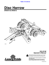
Figure4
1.Locknut
3.Clevispin
2.Longbolt4.Frontstabilizerleg
6.Installthelongboltthroughtheholes,andsecureit
withalocknuttorquedto102N-m(75ft-lb);referto
Figure4.
Note:Thestabilizerlegpivotsrearwardonthebolt.
Ifyouinstalltheboltintothewronghole,thestabilizer
legwillnotworkproperly.
7.Inserttheclevispin(Figure4)tolockthefront
stabilizerleginposition.
Note:Rotatethestabilizerlegupfortowingthemachine,
anddownwhenthemachineisstationary.Alwaysinsertthe
clevispinthroughtheappropriateholestoensurethatthe
stabilizerlegdoesnotmoveunexpectedly.
2
InstallingtheHitchAssembly
Partsneededforthisprocedure:
1Hitchassembly
2Flange-headbolt
2Locknut
Procedure
1.Using2ange-headboltsand2locknuts,loosely
installthehitchassemblyinthemiddlepositionofthe
mountingplate.
Figure5
Ballhitchshown
1.Locknut(2)3.Flange-headbolt(2)
2.Mountingplate4.Hitchassembly
2.Positionthemachinesothatthetowpoleislevel.
3.Checktherelationshipbetweenthehitchofthe
machineandthehitchofthetowvehicle,andmount
thehitchassemblyin1ofthefollowingpositions:
•Ifthehitchesareapproximatelythesameheight,
keepthehitchassemblyinthemiddlepositionof
themountingplate;refertoFigure6.
•Ifthehitchofthetowvehicleishigh,mountthe
hitchassemblyinthetopposition.
•Ifthehitchofthetowvehicleislow ,mountthe
hitchassemblyinthebottomposition.
3