TP-7190 4/21 5Safety Precautions and Instructions
Safety Precautions and Instructions
IMPORTANT SAFETY INSTRUCTIONS.
Electromechanical equipment,
including generator sets, transfer
switches, switchgear, and accessories,
can cause bodily harm and pose
life-threatening danger when
improperly installed, operated, or
maintained. To prevent accidents be
aware of potential dangers and act
safely. Read and follow all safety
precautions and instructions. SAVE
THESE INSTRUCTIONS.
This manual has several types of safety
precautions and instructions: Danger,
Warning, Caution, and Notice.
DANGER
DANGER indicates a hazardous
situation which, if not avoided, will
result in death or serious injury.
WARNING
WARNING indicates a hazardous
situation which, if not avoided, could
result in death or serious injury.
CAUTION
CAUTION indicates a hazardous
situation which, if not avoided, could
result in minor or moderate injury.
NOTICE
NOTICE is used to address practices
not related to physical injury.
Safety decals affixed to the equipment
in prominent places alert the operator
or service technician to potential
hazards and explain how to act safely.
The decals are shown throughout this
publication to improve operator
recognition. Replace missing or
damaged decals.
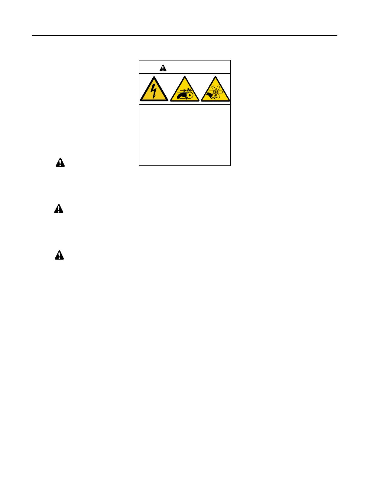
Accidental Starting
Accidental starting.
Can cause severe injury or death.
Disconnect the battery cables before
working on the generator set.
Remove the negative (- ) lead first
when disconnecting the battery.
Reconnect the negative (- ) lead last
when reconnecting the battery.
WARNING
Disabling the generator set.
Accidental starting can cause
severe injury or death. Before
working on the generator set or
equipment connected to the set,
disable the generator set as follows:
(1) Move the generator set master
switch to the OFF position.
(2) Disconnect the power to the battery
charger. (3) Remove the battery
cables, negative (- ) lead first.
Reconnect the negative (- ) lead last
when reconnecting the battery. Follow
these precautions to prevent starting of
the generator set by an automatic
transfer switch, remote start/stop
switch, or engine start command from a
remote computer.
(Decision-Makerr3+ and 550
Generator Set Controllers)
Disabling the generator set.
Accidental starting can cause
severe injury or death. Before
working on the generator set or
equipment connected to the set,
disable the generator set as follows:
(1) Press the generator set off/reset
button to shut down the generator set.
(2) Disconnect the power to the battery
charger, if equipped. (3) Remove the
battery cables, negative (- ) lead first.
Reconnect the negative (- ) lead last
when reconnecting the battery. Follow
these precautions to prevent the
starting of the generator set by the
remote start/stop switch.
(APM402, APM603, RDC, DC, RDC2,
DC2, Decision-Makerr3000, 3500
and 6000 Generator Set Controllers)
Disabling the generator set.
Accidental starting can cause
severe injury or death. Before
working on the generator set or
equipment connected to the set,
disable the generator set as follows:
(1) If the controller is not already in the
MAN (manual) mode, press the
Controller Mode button and then press
the MAN mode button. (2) If the
generator set is running, press and hold
the Manual- Stop button for at least
2 seconds to stop the generator set.
(3) Press the Controller Mode button
and then press the controller Off mode
button. (4) Disconnect the power to the
battery charger, if equipped.
(5) Remove the battery cables,
negative (- ) lead first. Reconnect the
negative (- ) lead last when
reconnecting the battery. Follow these
precautions to prevent the starting of
the generator set by the remote
start/stop switch.
(Decision-Makerr8000 Controller)


