1
© 2020. All rights reserved.
115V / 12V DC
BACKUP SUMP PUMP
COMBO SYSTEM
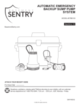
MODEL #STBC101
Purchase Date
Questions, problems, missing parts? Before returning to your retailer, call our customer
service department at 1-800-742-5044, 7:30 a.m. - 5:00 p.m., EST, Monday - Friday.
ATTACH YOUR RECEIPT HERE
Español p. 13
SW1474 A
BasementSentry.com

2
© 2020. All rights reserved.
PACKAGE CONTENTS
SAFETY INFORMATION
DESCRIPTION QUANTITY
A Primary/backup pump
and pipe assembly
(Includes: AC pump,
DC pump, elbows, tee,
check valves, DC oat,
discharge pipe and ex
coupling/clamps)
1
B Battery box with built-in
controller
1
C AC wall adapter 1
Please read and understand this entire manual before attempting to assemble, operate, or install the
product.
DANGER
• RISK OF CHEMICAL BURNS.
Battery acid is corrosive. Do not spill on skin, clothing or battery charger. Wear eye and head
protection when working with battery. Connect and disconnect DC output terminals only after
removing the charger from the AC outlet. Never allow the DC terminals to touch each other.
• FIRE/EXPLOSION HAZARD.
Keep sparks and flame (pilot light) away from battery.
• FIRE/EXPLOSION HAZARD.
Pump only clear water. Do not pump flammable or explosive fluids such as gasoline, fuel oil,
kerosene, etc. Do not use in a flammable and/or explosive atmosphere. Failure to follow these
warnings could result in death or serious injury and/or property damage.
• RISK OF ELECTRIC SHOCK.
These pumps have not been investigated for use in swimming pool or marine areas.
• RISK OF ELECTRIC SHOCK.
Always disconnect power source before attempting to install, service, or maintain the pump.
Never handle a pump with wet hands or when standing on wet or damp surface or in water. Fatal
electrical shock could occur.
• RISK OF ELECTRIC SHOCK.
Keep pump out of reach of children.
• PERSONAL INJURY OR PRODUCT DAMAGE MAY RESULT.
Failure to comply with instructions and designed operation of this product may void warranty.
Attempting to use a damaged pump can result in property damage, serious personal injury and/or
death.
A
B
C

3
© 2020. All rights reserved.
WARNING
• ELECTRICAL SHOCK ALERT.
Do not disassemble the motor housing. The motor has NO repairable internal parts and
disassembly may cause dangerous electrical wiring issues.
• ELECTRICAL SHOCK ALERT.
Before installing this product, have the electrical circuit checked by an electrician to ensure proper
grounding. All electrical installations must conform to the National Electric Code and all local
codes.
• ELECTRICAL SHOCK ALERT.
Connect the AC adapter to a properly-grounded 115 volt circuit equipped with a Ground Fault
Circuit Interrupter (GFCI) device. Make sure the electrical supply circuit is equipped with fuses or
circuit breakers with a minimum capacity of 15 amps.
• ELECTRICAL SHOCK ALERT.
Never use an extension cord.
• ELECTRICAL SHOCK ALERT.
Do not remove or replace the power cord.
• ELECTRICAL SHOCK ALERT.
Protect electrical cord from sharp objects, hot surfaces, oil, and chemicals. Avoid kinking the cord.
• ELECTRICAL SHOCK ALERT.
Do not lift pump by the power cord.
• PERSONAL INJURY ALERT.
Do not touch an operating motor housing. The motor is designed to operate at high temperatures.
• PERSONAL INJURY ALERT.
Release all pressure and drain all water from the system before servicing any component.
• PERSONAL INJURY ALERT.
Secure discharge line before starting pump. An unsecured discharge line can cause personal
injury and/or property damage.
• PERSONAL INJURY ALERT.
Wear safety glasses at all times when working with pumps.
• PROP65 WARNING FOR CALIFORNIA RESIDENTS:
Cancer and Reproductive Harm – www.P65Warnings.ca.gov
CAUTION
• PERSONAL INJURY OR PRODUCT DAMAGE MAY RESULT.
The AC adapter operates on 115 volts. Make certain that the power source conforms to the
requirements of your equipment.
• PRODUCT DAMAGE MAY RESULT.
The continuous operating water temperature for this pump must not exceed 104°F (40°C).
• PRODUCT DAMAGE MAY RESULT.
This pump is designed to pump water only. It has not been evaluated for pumping chemicals or
corrosive materials. This pump is not designed for pumping effluent or sewage and should not be
used in applications involving salt water or brine.
• PRODUCT DAMAGE MAY RESULT.
Inspect the pump regularly for damage and perform routine maintenance as needed. Remove any
debris that may build up around the float.
• PRODUCT AND/OR PROPERTY DAMAGE MAY RESULT.
This pump is not designed for continuous operation.

4
© 2020. All rights reserved.
PREPARATION
Estimated Installation Time: 1-2 hours
Materials required for assembly: Basement Sentry brand deep cycle battery, 1-1/2-in. Schedule 40
PVC pipe and fittings, PVC primer and glue, Phillips screw driver, hand saw
GENERAL PUMP INFORMATION
SPECIFICATIONS
PUMP
PERFORMANCE IN GALLONS PER MINUTE
0 FT. 5 FT. 10 FT. 15 Ft.
115V 40 36 28 10
12V DC 29 20 10 14 Ft. Shut Off
This complete combo system will replace an existing 115V pump. This pump provides additional
protection against basement ooding when the power ges out. It is designed to work only during
power outages or if the primary pump does not work. Because the system is pre-assembled,
installation is quick and easy. The system includes a 115V pump, 12V pump, controller, alarm
system, battery charger, oat switch and battery box.
The sump basin must be at least 22-in deep by 18-in diameter.
This backup system requires a good quality, deep cycle battery in order to provide maximum pumping
time when needed. A Basement Sentry brand battery is recommended. Otherwise, use an AGM deep-
cycle 12 volt 105 amp-hour marine battery or larger. Wet cell batteries contain acid and precautions
must be taken when handling.
DO NOT USE gel batteries or automotive batteries. Batteries with top terminals are recommended for
ease of installation.
NOTE: Pump must be submerged in water before operation. Running the pump dry will cause
damage and void the warranty.
NOTE: The alarm will sound after connecting the battery. It will continue to sound until all
connections are made and the oat switch is in the down position.
The pump will continue to run for an additional 10 seconds after the float has been lowered. The
alarm will continue to sound while the pump is working.
Place the battery in a cool, dry, well-ventilated area on a shelf or protective plywood board. If a carbon
monoxide (CO detector) is installed in the same area as the DC pump system, it must be at least 15
feet away from the battery in order to avoid nuisance CO alarms. Refer to CO detector installation
guidelines for more information.

5
© 2020. All rights reserved.
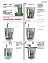
INSTALLATION INSTRUCTIONS
NOTE: Install the battery backup system when the
primary pump is not needed. Read instructions and
prepare all supplies before beginning installation.
1. Manually operate the existing sump pump to
remove as much water as possible from the
basin.
Manually
lift float
1
2. Disconnect the existing pump from the power
source. Disconnect or cut the main discharge
pipe and separate the primary sump pump from
the discharge pipe. Remove the pump from the
sump basin.
WARNING: Never handle a pump with wet
hands or when standing on wet or damp
surface or in water. Fatal electrical shock
could occur.
3. Remove any dirt or accumulated debris from the
sump pit and surrounding area.
Remove
debris
3
115 V
GFCI outlet
2

6
© 2020. All rights reserved.
4. Place the 115V / 12VDC pump assembly in the
sump basin.
5. Measure the distance between the household
discharge pipe and the top of the115V / 12V DC
pump assembly. Cut Sched 40 PVC pipe to fit
this measurement.
Household
discharge
piping
Flex
coupling
5
4
INSTALLATION INSTRUCTIONS
6. Dry-fit the pipe connections to be sure measurements
are connected. Insert the new connecting pipe into
the top of the pump assembly flex coupling. Glue the
connecting pipe to the household discharge pipe with
PVC glue and primer. Securely tighten the clamps on
the flex coupling.
Sched 40 PVC
6

7
© 2020. All rights reserved.
7. Place a fully-charged, deep-cycle marine battery inside
the battery box. Connect the leads inside the battery
box from the controller to the battery:
Red (+) to battery Red (+)
Black (-) to battery Black (-)
WARNING: Connecting the wires to the wrong
terminals on the battery may cause damage to the
controller.
NOTE: The alarm will sound after connecting
the battery. It will continue to sound until all
connections are made and the float switch is in
the down position.
NOTE: Be sure the battery box ventilation holes are
unobstructed. Battery control box must be set up in a
well-ventilated area, away from any smoke, flames or
pilot lights.
8. Connect system wires to the controller on the top of
the battery box lid.
a. Plug the pump wire into the port marked ‘PUMP’.
b. Plug the float switch wire into the port marked
‘FLOAT’.
c. Plug the 12V charger into the port marked
‘ADAPTER’. Plug the charger into a 115V GFCI
protected power source.
Once the charger is plugged in, the LED lights on the
battery box should turn on.
9. Test DC pump operation by lifting up the DC float
switch and holding it in place. The pump ‘Pump
Status’ LED will show a continuous light and the
alarm will beep steadily. The pump should start at this
time. If it doesn’t start, check all connections.
NOTE: The pump will continue to run for an
additional 10 seconds after the float has been
lowered. The alarm will continue to sound while the
pump is working.
SW1401 A
Red light on and alarm sounds:
Battery backup pump working
Red light slow flash and alarm sounds:
Pump wire connection problems or pump failed
Yellow light on:
Battery recharging
Yellow light slow flash and alarm sounds:
Power off or power adapter failed
Yellow light quick flash and alarm sounds:
Battery disconnected or DC fuse broken
Green light on:
System is normal
RESET
Pump Status LED
9
ADAPTER
FLOAT
SWITCH PUMP
8
7
INSTALLATION INSTRUCTIONS

8
© 2020. All rights reserved.
10. Test all system connections by pressing the
‘RESET’ button for 1 - 4 seconds. The alarm will
sound. This will cause the system to run a self-
test and the DC pump will run for 3 seconds.
To silence an alarm, press the ‘RESET’ button,
hold for 4 - 8 seconds and release. The alarm
should stop.
After the system returns to normal status, the
alarm will automatically reset.
11. LED Indicator Lights
Red light on and alarm sounds:
Battery backup pump is working
Red light slow flash and alarm sounds:
Pump wire connection problems or pump
failure
Yellow light on:
Battery is recharging
Yellow light slow flash and alarm sounds:
Power off or power adapter failure
Yellow light quick flash and alarm sounds:
Battery is disconnected or DC fuse broken
Green light on:
The system is normal
SW1401 A
Red light on and alarm sounds:
Battery backup pump working
Red light slow flash and alarm sounds:
Pump wire connection problems or pump failed
Yellow light on:
Battery recharging
Yellow light slow flash and alarm sounds:
Power off or power adapter failed
Yellow light quick flash and alarm sounds:
Battery disconnected or DC fuse broken
Green light on:
System is normal
RESET
RedYellow
Green
11
SW1401 A
Red light on and alarm sounds:
Battery backup pump working
Red light slow flash and alarm sounds:
Pump wire connection problems or pump failed
Yellow light on:
Battery recharging
Yellow light slow flash and alarm sounds:
Power off or power adapter failed
Yellow light quick flash and alarm sounds:
Battery disconnected or DC fuse broken
Green light on:
System is normal
RESET
Press Reset
10
INSTALLATION INSTRUCTIONS
12. Completed Installation
12

9
© 2020. All rights reserved.
NOTE: Sump basin must be filled with water before
operation. Running the pump dry will cause
damage and void the warranty.
1. Verify 115V pump operation by filling the basin
with enough water to raise the float on the
primary sump pump. Pump should start and
remove water.
Unplug the 115V from the power source.
2. Test DC pump operation by refilling the sump
basin with water until the DC pump float moves
to the top of the float rod.
The DC pump should start and pump water out
of the sump basin. If pump does not operate,
check all wire connections.
Backup
sump
pump
Lift
float
up
2
Primary
sump
pump
Lift
float
up
1
OPERATION

10
© 2020. All rights reserved.
CARE AND MAINTENANCE
WARNING: Always disconnect pump from power source
before handling.
Once a month:
Press the reset button for 1-3 seconds to run a
self-test.
At least every three months:
• Remove any debris that may build up in the sump
basin to prevent it from interfering with the operation of
the float switch.
• Clean out the vent hole in the discharge pipe.
• Test system for operation.
Follow the battery manufacturer’s recommendations for
maintenance and safe use of the battery. Replace battery
as needed.
WARNING: An acid-filled standard lead-acid battery
contains sulfuric acid. Avoid contact with skin, eyes or
clothing.
Remove
debris
Clean out
vent hole
1
WARRANTY
This product is warranted for one year from the date of purchase or two years from the date of manufacture,
whichever occurs rst. Subject to the conditions hereinafter set forth, the manufacturer will repair or replace
to the original consumer, any portion of the product which proves defective due to defective materials or
workmanship. This warranty does not cover replacement parts for failure due to normal wear and tear. To
obtain warranty service, contact the retailer from whom the product was purchased. The manufacturer retains
the sole right and option to determine whether to repair or replace defective equipment, parts or components.
Damage due to conditions beyond the control of the manufacturer is not covered by this warranty. For warranty
questions or service, call 1-800-742-5044.
THIS WARRANTY WILL NOT APPLY: (a) To defects or malfunctions resulting from failure to properly install,
operate or maintain the unit in accordance with printed instructions provided; (b) to failures resulting from
abuse, accident or negligence; (c) to normal maintenance services and the parts used in connection with
such service; (d) to units which are not installed in accordance with normal applicable local codes, ordinances
and good trade practices; and (e) the unit is used for purposes other than for what it was designed and
manufactured.
RETURN OF WARRANTED COMPONENTS: Any item to be repaired or replaced under this warranty must be
returned to the manufacturer at such place as the manufacturer may designate, freight prepaid.
THE WARRANTY PROVIDED HEREIN IS IN LIEU OF ALL OTHER EXPRESS WARRANTIES, AND MAY
NOT BE EXTENDED OR MODIFIED BY ANYONE. ANY IMPLIED WARRANTIES SHALL BE LIMITED TO
THE PERIOD OF THE LIMITED WARRANTY AND THEREAFTER ALL SUCH IMPLIED WARRANTIES ARE
DISCLAIMED AND EXCLUDED. THE MANUFACTURER SHALL NOT, UNDER ANY CIRCUMSTANCES, BE
LIABLE FOR INCIDENTAL, CONSEQUENTIAL OR SPECIAL DAMAGES, SUCH AS, BUT NOT LIMITED TO
DAMAGE TO, OR LOSS OF, OTHER PROPERTY OR EQUIPMENT, LOSS OF PROFITS, INCONVENIENCE,
OR OTHER INCIDENTAL OR CONSEQUENTIAL DAMAGES OF ANY TYPE OR NATURE. THE LIABILITY
OF THE MANUFACTURER SHALL NOT EXCEED THE PRICE OF THE PRODUCT UPON WHICH SUCH
LIABILITY IS BASED.
This warranty gives you specic legal rights, and you may have other rights which vary from state to
state. Some states do not allow limitations on duration of implied warranties or exclusion of incidental or
consequential damages, so the above limitations may not apply to you.
In those instances where damages are incurred as a result of an alleged pump failure, the
Homeowner must retain possession of the pump for investigation purposes.

11
© 2020. All rights reserved.
TROUBLESHOOTING
PROBLEM POSSIBLE CAUSE CORRECTIVE ACTION
Pump will not
start or run
(Red light
comes on briefly
and shuts off)
1. Wire connection issues 1. Check all the wiring connections.
2. Battery issue 2. Check for a low or defective
battery. Replace if needed.
3. Switch is stuck 3. Check to be sure the oat switch
is free to move up and down on
the oat switch rod.
4. Debris in pump inlet 4. Check for obstructions in pump.
Motor hums but
pump doesn’t
pump water
1. Battery issue 1. Check for a low or defective
battery. Replace if needed.
Flow rate is too
low
1. The discharge pipe length and/or
height exceeds the capacity of the
pump.
1. Re-configure the discharge pipe
length or height to fit system
specifications.
2. Low battery 2. Replace the battery or charge the
battery. It may take a few days to
bring the voltage on the battery
back up after heavy usage.
Pump cycles
frequently
1. The check valve located between the
discharge of the primary pump and the
backup pump tee is not installed or is
not working properly.
1. Install or replace check valve.
Pump runs
but water level
stays high
1. Battery issue 1. Check for a low or defective
battery. Replace if needed.
2. If power is restored to primary pump,
pump may require service.
2. Check primary pump and service
or replace as needed.
Slow flashing
red light and
alarm.
1. Pump wire connection 1. Check to make sure pump is
properly plugged into the
controller.
Light and alarm
will not clear
when holding
2. Debris in impeller 2. Check if pump is moving water.
Pump may be seized. Check for
debris stuck in impeller.
the reset button.
3. Pump Problem 3. Replace pump if pump is not
moving water and no debris is
interfering with impeller.
NOTE: Battery and wall adapter power must be removed to clear this fault.
RISK OF ELECTRIC SHOCK.
Always disconnect power source before attempting to install, service, or maintain the pump. Never
handle a pump with wet hands or when standing on wet or damp surface or in water. Fatal electrical
shock could occur.
DANGER

12
© 2020. All rights reserved.
REPAIR PARTS
ITEM P/N DESCRIPTION
A 025400 12V DC Pump
B 025404
Battery Box w/
controller
C 025402 Float Switch
D 025403 AC Adapter
E 025401 90º Elbow
A
B
C
D
E

13
© 2020. Todos los derechos reservados.
115V / 12V CD BACKUP
SISTEMA COMBINADO
CON BOMBA DE
SUMIDERO DE
RESERVA
MODELO #STBC101
SW1474 A
BasementSentry.com
Número de serie
Fecha de compra
¿Preguntas, problemas, partes faltantes? Antes de acudir al minorista, llame a nuestro
departamento de servicio al cliente al 1-800-742-5044, de lunes a viernes de
7:30 a.m. a 5:00 p.m., EST.
ADJUNTE SU RECIBO AQUÍ

14
© 2020. Todos los derechos reservados.
CONTENIDO DEL PAQUETE
ADVERTENCIA
DESCRIPCIÓN CANTIDAD
A Conjunto de bomba principal/
reserva y tubería
(Incluye: Bomba de CA,
bomba de CC, codos, T,
válvulas de retención, otador
de CC, tubo de descarga y
acoples/abrazaderas exibles)
1
B Caja de batería con
controlador incorporado
1
C Adaptador de pared de CA 1
PELIGRO
• RIESGO DE QUEMADURAS QUÍMICAS.
El ácido de batería es corrosivo. No lo derrame sobre la piel, la ropa o el cargador de batería. Use
protección para los ojos y la cabeza al trabajar con baterías. Conecte y desconecte los terminales de
salida de CC solo después de haber desconectado el cargador de la toma de CA. No permita nunca que
los terminales de CC entren en contacto..
• PELIGRO DE INCENDIO/EXPLOSIÓN.
Mantenga las chispas y la llama (luz piloto) apartadas de la batería.
• PELIGRO DE INCENDIO/EXPLOSIÓN.
Bombee solo agua limpia. No bombee líquidos inflamables o explosivos como gasolina, gasoil, queroseno,
etc. No la utilice en una atmósfera inflamable o explosiva. No seguir estas instrucciones puede provocar la
muerte, lesiones graves o daños a la propiedad.
• RIESGO DE DESCARGA ELÉCTRICA.
No se ha verificado el uso de estas bombas en piscinas.
• RIESGO DE DESCARGA ELÉCTRICA.
Desconecte siempre la fuente de alimentación antes de intentar instalar, reparar o realizarle mantenimiento
a la bomba. Nunca manipule una bomba con las manos mojadas ni cuando esté parado sobre una
superficie húmeda o en el agua. Podría ocurrir una descarga eléctrica fatal.
• RIESGO DE DESCARGA ELÉCTRICA.
Mantenga la bomba alejada del alcance de los niños.
• PODRÍAN PRODUCIRSE LESIONES PERSONALES O DAÑOS AL PRODUCTO.
El incumplimiento de las instrucciones y del funcionamiento diseñado de este producto podría invalidar la
garantía. Intentar usar una bomba dañada puede provocar daños materiales, lesiones personales graves
y/o la muerte.
A
B
C
INFORMACIÓN DE SEGURIDAD
Lea y comprenda todo el manual antes de intentar ensamblar, operar o instalar el producto.
• ALERTA DE DESCARGA ELÉCTRICA.
No desensamble la carcasa del motor. El motor NO contiene piezas internas que se puedan reparar y el
desmontaje podría ocasionar problemas peligrosos por el cableado eléctrico.

15
© 2020. Todos los derechos reservados.
• ALERTA DE DESCARGA ELÉCTRICA
Antes de instalar este producto, haga que un electricista revise su circuito para asegurarse de que la
puesta a tierra sea adecuada. Todas las instalaciones eléctricas deben cumplir con el Código Nacional de
Electricidad (NEC, por sus siglas en inglés) y con todos los códigos locales.
• ALERTA DE DESCARGA ELÉCTRICA.
Conecte el adaptador de CA a un circuito de 115 V con la debida conexión a tierra equipado con un
interruptor de circuito con protección de falla a tierra (GFCI, por sus siglas en inglés). Asegúrese de que el
circuito de suministro eléctrico esté equipado con fusibles o disyuntores con una capacidad mínima de 15
amperios.
• Nunca utilice una extensión eléctrica.
• ALERTA DE DESCARGA ELÉCTRICA
No retire ni reemplace el cable eléctrico..
• ALERTA DE DESCARGA ELÉCTRICA
Proteja el cable eléctrico de objetos afilados, superficies calientes, aceite y otras sustancias químicas.
Evite torcer el cable.
• ALERTA DE DESCARGA ELÉCTRICA
No alce la bomba por el cable de alimentación.
• ALERTA DE LESIONES PERSONALES.
No toque la carcasa de un motor en funcionamiento. El motor está diseñado para funcionar a altas
temperaturas.
• ALERTA DE LESIONES PERSONALES.
Libere toda la presión y drene toda el agua del sistema antes de reparar o darle mantenimiento a cualquier
componente..
• ALERTA DE LESIONES PERSONALES.
Asegure la línea de descarga antes de encender la bomba. Una línea de descarga que no esté asegurada
puede causar lesiones personales y/o daños materiales.
• ALERTA DE LESIONES PERSONALES.
Use gafas de seguridad todo el tiempo cuando trabaje con bombas.
• ADVERTENCIA DE PROPOSICIÓN 65 PARA RESIDENTES DE CALIFORNIA
Cáncer y Daño Reproductivo – www.P65Warnings.ca.gov
PRECAUCIÓN
• PODRÍAN PRODUCIRSE LESIONES PERSONALES O DAÑOS EN EL PRODUCTO.
El adaptador de CA opera a 115 V. Asegúrese de que la fuente de alimentación cumpla con los requisitos
de su equipo.
• PODRÍAN PRODUCIRSE DAÑOS EN EL PRODUCTO.
La temperatura del agua de funcionamiento continuo para este modelo de bombas no debe sobrepasar
40 °C (104 °F).
• PODRÍAN PRODUCIRSE DAÑOS EN EL PRODUCTO.
Esta bomba fue diseñada solo para bombear agua. No se ha probado su uso para bombear productos
químicos ni materiales corrosivos. Esta bomba no está diseñada para bombear efluentes o aguas negras y
no debería usarse en aplicaciones que involucren agua salada o salmuera.
• PODRÍAN PRODUCIRSE DAÑOS EN EL PRODUCTO.
Revise de manera regular que la bomba no presente daños y realícele mantenimiento de rutina cuando
sea necesario. Quite la suciedad que pudiera acumularse alrededor del flotador.
• PODRÍAN PRODUCIRSE DAÑOS AL PRODUCTO Y/U OTROS DAÑOS MATERIALES.
Esta bomba no está diseñada para su funcionamiento continuo.

16
© 2020. Todos los derechos reservados.
PREPARACIÓN
Tiempo estimado de ensamblaje: 1-2 horas
Materiales necesarios para en ensamblaje: Batería de ciclo profundo marca Basement Sentry
de 3.8 cm (1-1/2 pulg.) Tubo y accesorios de PVC Schedule 40, imprimación y pegamento de PVC,
destornillador Phillips, sierra de mano
GENERAL PUMP INFORMATION
ESPECIFICACIONES
BOMBA
RENDIMIENTO EN GALONES POR MINUTO
0 PIES 5 PIES 10 PIES 15 PIES
115V 40 36 28 10
12V CC 29 20 10 14 Pies Cierre
Este sistema combinado completo reemplazará una bomba de 115V. Esta bomba proporciona
protección adicional contra inundaciones en caso de apagones. Está diseñada para funcionar
solo durante cortes de energía o si la bomba principal no funciona. Debido a que el sistema está
preensamblado, la instalación es rápida y fácil. El sistema incluye una bomba de 115 V, una bomba
de 12 V, controlador, sistema de alarma, cargador de batería, interruptor de otador y caja de
batería.
El contenedor para agua de sumidero debe ser como mínimo de 55.88 cm (22 pulg.) de profundidad por 45.72
cm (18 pulg.) de diámetro.
Este sistema de respaldo requiere una batería de 12 V de buena calidad para proporcionar el máximo tiempo
de bombeo cuando sea necesario. Se recomienda un cargador de marca Basement Sentry. De lo contrario,
use una batería marina AGM de ciclo profundo de 12 voltios y 105 amp-hora o más grande. Las baterías
húmedas contienen ácido y hay que tener precaución al manipularlas.
NO USE baterías de gel o baterías automotrices. Se recomiendan baterías con terminales superiores para
facilitar la instalación.
NOTA: la bomba debe ser sumergida en agua antes de funcionar. Operar la bomba en seco provocará daños
y anulará la garantía.
NOTA: la alarma sonará tras conectar la batería. Continuará sonando hasta que se hayan realizado todas las
conexiones y el interruptor de otador esté en la posición de abajo.
La bomba continuará funcionando durante 10 segundos adicionales una vez que el otador haya descendido.
La alarma continuará sonando mientras la bomba esté en funcionamiento.
Coloque la batería en un área fresca, seca y bien ventilada sobre un estante o un tablero contrachapado
protector. Si se instala un detector de monóxido de carbono (CO) en la misma área que el sistema de bomba
de CC, debe estar al menos a 4.6 m (15 pies) de distancia de la batería para evitar alarmas molestas alarmas
de CO. Consulte las pautas para la instalación de detectores de CO para obtener más información.

17
© 2020. Todos los derechos reservados.
INSTRUCCIONES DE INSTALACIÓN
NOTA: instale el sistema de respaldo de batería cuando
no se necesite la bomba principal. Lea las instrucciones
y prepare todos los materiales antes de comenzar la
instalación.
1. Opere manualmente la bomba de sumidero principal
para retirar la mayor cantidad posible de agua del
contenedor para agua.
Levantar
manualmente
el flotador
1
2. Desconecte la bomba existente de la fuente de
energía. Desconecte o corte la tubería de descarga
principal y separe la bomba de sumidero principal
de la tubería de descarga. Retire la bomba del
contenedor para agua de sumidero.
ADVERTENCIA: No manipule la bomba con las
manos mojadas o cuando esté parado sobre una
supercie mojada, húmeda o con agua. Puede
ocurrir una descarga eléctrica mortal.
3. Retire de la fosa del sumidero y del área
adyacente cualquier tipo de suciedad o escombros
acumulados.
Elimine la
suciedad
3
115 V
GFCI outlet
2

18
© 2020. Todos los derechos reservados.
4. Coloque el conjunto de la bomba de 115V / 12VDC
en el contenedor para agua de sumidero.
5. Mida la distancia entre la tubería de descarga
doméstica y la parte superior del conjunto de la
bomba de 115V / 12V DC. Corte la tubería de PVC
Schedule 40 para adaptarse a esta medida.
Tubería de
descarga
doméstica
Acoplamiento
flexible
5
4
INSTRUCCIONES DE INSTALACIÓN
6. Ajuste en seco las conexiones de la tubería para
asegurarse de que las mediciones estén conectadas.
Inserte la nueva tubería de conexión en la parte superior
del acoplamiento flexible del conjunto de la bomba. Pegue
la tubería de conexión a la tubería de descarga doméstica
con pegamento de PVC e imprimación. Apriete firmemente
las abrazaderas en el acoplamiento flexible.
PVC Schedule 40
6

19
© 2020. Todos los derechos reservados.
7. Coloque una batería marina de ciclo profundo
completamente cargada en el interior de la caja de la
batería. Conecte los cables de la caja de la batería desde
el controlador hasta la batería:
Rojo (+) a Rojo de la batería (+)
Negro (-) a Negro de la batería (-)
NOTA: la alarma sonará tras conectar la batería.
Continuará sonando hasta que se hayan realizado
todas las conexiones y el interruptor de flotador esté
en la posición de abajo.
NOTA: asegúrese de que los orificios de ventilación de la
caja de la batería no estén obstruidos. La caja de control
de la batería debe colocarse en un área bien ventilada,
apartada de cualquier tipo de humo, llamas o luces piloto.
8. Conecte los cables del sistema al controlador en la parte
superior de la tapa de la caja de la batería.
a. Enchufe el cable de la bomba en el puerto marcado
como “PUMP” (bomba).
b. Enchufe el cable del interruptor de flotador en el
puerto marcado como “FLOAT” (flotador).
c. Enchufe el cargador de 12 V en el puerto marcado
como “ADAPTER” (adaptador). Enchufe el cargador
en una fuente de alimentación de 115 V protegida por
GFCI.
Una vez que el cargador esté enchufado, las luces LED
de la caja de la batería deberían encenderse.
9. Compruebe el funcionamiento de la bomba de CC
llenando el interruptor de flotador de CC y manteniéndolo
en su lugar. El LED de estado de la bomba estará
continuamente iluminado y la alarma pitará de forma
constante. La bomba debería arrancar en este momento.
Si no arranca, compruebe todas las conexiones.
NOTA: La bomba continuará funcionando durante 10
segundos adicionales una vez que el flotador haya
descendido. La alarma continuará sonando mientras la
bomba esté en funcionamiento.
SW1401 A
Red light on and alarm sounds:
Battery backup pump working
Red light slow flash and alarm sounds:
Pump wire connection problems or pump failed
Yellow light on:
Battery recharging
Yellow light slow flash and alarm sounds:
Power off or power adapter failed
Yellow light quick flash and alarm sounds:
Battery disconnected or DC fuse broken
Green light on:
System is normal
RESET
LED de estado de la bomba
9
ADAPTER
FLOAT
SWITCH PUMP
8
7
INSTRUCCIONES DE INSTALACIÓN

20
© 2020. Todos los derechos reservados.
10. Compruebe todas las conexiones del sistema
presionando el botón “RESET” (restablecer) durante 1
a 4 segundos. Sonará la alarma. Esto provocará que el
sistema realice una autocomprobación y la bomba de
CC funcionará durante 3 segundos.
Para terminar la prueba, presione el botón “RESET”,
manténgalo oprimido durante 4 a 8 segundos y suéltelo.
La alarma debería detenerse.
Después de que el sistema regrese al estado normal, la
alarma se restablecerá automáticamente.
11. Luces indicadoras LED
Luz verde encendida:
el sistema está normal.
Parpadeo rápido de la luz amarilla y la alarma suena:
la batería está desconectada o el fusible de CC está
roto
Parpadeo lento de la luz amarilla y la alarma suena:
la energía está apagada o falla del adaptador de
energía
Luz amarilla encendida:
la batería se está recargando
Luz roja encendida y la alarma suena:
la bomba con batería de reserva está funcionando
Parpadeo lento de la luz roja y la alarma suena:
Problemas con la conexión de los cables de la bomba
o falla de la bomba
SW1401 A
Red light on and alarm sounds:
Battery backup pump working
Red light slow flash and alarm sounds:
Pump wire connection problems or pump failed
Yellow light on:
Battery recharging
Yellow light slow flash and alarm sounds:
Power off or power adapter failed
Yellow light quick flash and alarm sounds:
Battery disconnected or DC fuse broken
Green light on:
System is normal
RESET
rojaamarilla
verde
11
SW1401 A
Red light on and alarm sounds:
Battery backup pump working
Red light slow flash and alarm sounds:
Pump wire connection problems or pump failed
Yellow light on:
Battery recharging
Yellow light slow flash and alarm sounds:
Power off or power adapter failed
Yellow light quick flash and alarm sounds:
Battery disconnected or DC fuse broken
Green light on:
System is normal
RESET
Presione Reset
10
INSTRUCCIONES DE INSTALACIÓN
12. Instalación completada
12
Page is loading ...
Page is loading ...
Page is loading ...
Page is loading ...
/