Extron NBP 108 D Installation guide

Type
Installation guide

This manual is also suitable for

1
IMPORTANT:
IMPORTANT:
Go to www.extron.com for the complete
user guide, installation instructions, and
specifications before connecting the
product to the power source.
Network Button Panel — Decorator-Style Series •
Setup Guide
Overview
The Extron NBP Network Button Panels are fully customizable AV system control interfaces for use with Extron control processors
(IPCPPro, IPCPProQxi, IPCPProxi,or IPLPro Series and collaboration system products). The NBPs in this guide fit a standard
US one-gang electrical junction box or mud ring. They have one-gang decorator-style wallplates (one white, one black for each
NBP), front panel bezels (white and black), and a one-gang mud ring. Each NBP button panel has a single LAN port, which
supports both power and communications between the control processor and button panels.
Use Extron Toolbelt software to discover and manage NBP button panels and assign each one a unique IP address. Then
use Extron GlobalConfigurator® (GC) Plus and Professional software, Global Scripter® programming, or the ControlScript®
Deployment Utility to configure the control system, including the buttons on NBPs. Once configured, the AV system can be
controlled from any of the NBPs.
This guide provides basic instructions for an experienced installer to install an NBP105D, NBP106D, NBP108D, NBP110D,
NBPVC1D, or NBPVC2D button panel. For more details on the NBPs, see the Network Button Panels User Guide, available on
www.extron.com. For details on configuration, see the software help files.
Conventions Used in This Guide
Throughout this guide a Network Button Panel is also referred to as an “NBP” or “button panel.”
The NBPs are compatible with the following control devices:
IPCPPro and IPLPro control processors
IPCPProQxi and IPCPProxi control processors
HCR102 collaboration system receiver (part of an HC400 Series system)
In this guide, those devices are referred to as “control processors.”
For details on those devices, see the IPCP Pro Series User Guide, IPL Pro Series User Guide, IPCPProQxi and xi Series User
Guide, or HC 400 Series User Guide (avail able from www.extron.com).
Global Configurator software is referred to as “GC,” which can be run as Global Configurator Professional or Global
Configurator Plus.
Global Scripter (GS) and ControlScript Deployment Utility can be used as programming-based alternatives to GC.
The GlobalViewer® Enterprise application is sometimes referred to as “GVE.”
Rev. D: Added a
conventions used
section, including a list
of compatible control
devices and a note that
this guide will call them
“control processors.”
Moved references to the
user guides for those
products to here.
2
Network Button Panel — Decorator-Style Series • Setup Guide (Continued)
Front Panel Features
DISPLAY
ON OFF
PC VIDEO
LAPTOP MUTE
VOLUME
VIDEO
PC
VOLUME
DISPLAY
OFF
ON
NBP 106 D
HDMI
MEDIA PLAYER
VIDEO
LAPTOP
PC
NBP 105 D
MEDIA
PLAYER MUTE
HDMI 1 HDMI 2
PC LAPTOP
ON OFF
NBP 110 DNBP 108 D
A
AA
C C
BB
D
E
D
Figure 1. Front Panels with Wallplates
A Function buttons — Configure these buttons to light
and function as desired.
B Power buttons — These buttons (present on certain
models only) are usually used to control the power to
the display device. The On button has a nub that can
be felt with finger tips.
C Communications LED — This LED (present on
certain models only) indicates the configuration and
connection status of the NBP.
Unlit — Normal operation (the NBP is configured
and connected to an IPCPPro control
processor).
Blinking red — The NBP has been configured
but is not connected to an IPCPPro control
processor.
Lit steadily — The NBP has not been configured.
D Volume buttons (some models), volume knob (NBPVC1D), or
microphone volume buttons (NBPVC2D) — Configure Volume
buttons, Microphone buttons, or the volume knob to increment or
decrement audio volume.
E Volume LEDs — Volume LEDs (present only on models with Volume
or Microphone buttons or a volume knob) light to act as a meter to
indicate the volume level.
F Reset button and LED — Pressing this recessed button (present on
all models) prepares the unit to use factory firmware, toggles the DHCP
client on or off, or causes various product settings to be reset to the
factory defaults (see Reset Modes: a Brief Summary on page9).
The LED is normally off except during resets and immediately after boot-up.
G Mute button (VC models, figure 2) — Configure the Mute button as desired
to mute output audio (for volume controls) or input audio (for microphone
controls).
All the function, power, and volume buttons must be configured or programmed
to carry out their functions. The buttons are backlit by LEDs.
The NBP decorator-style units have a buzzer located on a circuit board within
the unit. The behavior of the buzzer can be configured using Global Configurator
or programmed with Global Scripter to be globally disabled or to beep as desired
when a button is pressed.
NBP VC1 D NBP VC2 DNBP VC1
D
MUTE
VOLUME
MUTE
VO
LUME
NBP VC2 D
MUTE
MUTE
VOLUME
MICROPHONE
+
+
E
EG
D
E
G
D
Figure 2. NBPVC1D (Left), NBPVC2D (Right) Front Panels
Extron
Extron
PC
LAPTOP
VIDEO
MEDIA PLAYER
HDMI
Bezel Tab
Access Holes (2)
Bezel
(Faceplate)
Mounting
Holes (2)
Wallplate
Attachment
Holes (2)
F
Figure 3. NBP 105 D Front Panel
without Wallplate
Rev. D: Added
references to the
volume knob, mic
volume buttons,
and Mute button.
Added wording
reflecting the
various other
reset functions
aside from reset
to defaults.
Rev. B: Added info
on the buzzer.
3
Rear Panel Features
LAN (Ethernet) and PoE connector and LEDs — Connect the unit to a network via this connector for control and Power over
Ethernet. Use the following diagrams as a guide. All NBP one-gang decorator-style models have identical rear panel features.
LAN/PoE
MAC: 00-05-A6-XX-XX-XX
S/N: ####### E######
33-1720-22
B
U
CAN ICES-3(A)/NMB-3(A)
I.T.E.
E146728
LAN/PoE
(Ethernet)
connector
and LEDs
MAC Address
LAN/PoE
RJ-45
Connector
NBP Rear Panel LAN/PoE (Ethernet and
Power Over Ethernet)
Ethernet
NOTE:
MAC address information
(00-05-A6-XX-XX-XX) is located
on the rear of each decorator-style
enclosure.
PC
Link LED: Lights
green to indicate a
network connection.
Activity LED:
Blinks
amber to
indicate data
is being sent
or received.
TCP/IP
Network
Connect to an Ethernet network.
This port must be congured.
Default protocol:
• NBP address: 192.168.254.253
• Gateway IP address: 0.0.0.0
• Subnet mask: 255.255.255.0
• DNS address: 127.0.0.1
• DHCP: off
• Link speed and duplex level: autodetected
• Data rates: 10/100Base-T
Power over Ethernet (PoE):
The NBP receives power at this port.
Default login credentials:
• Username: admin or user
• Initial password: unit serial number
• Password after a “Full Factory Reset”:
extron
MAC: 00-05-A6-XX-XX-XX
S/N: XXXXXXX EXXXXXX
00-05-A6-XX-XX-XX
MAC: 00-05-A6-XX-XX-XX
S/N: XXXXXXX EXXXXXX
MAC
Address
Extron
Control
Processor
Figure 4. Rear Panel Features
ATTENTION:
Power over Ethernet (PoE) is intended for indoor use only. It is to be connected only to networks or circuits that are not
routed to the outside plant or building.
L’alimentation via Ethernet (PoE) est destinée à une utilisation en intérieur uniquement. Elle doit être connectée
seulement à des réseaux ou des circuits qui ne sont pas routés au réseau ou au bâtiment extérieur.
IMPORTANT NOTES:
The factory configured passwords for this device have been set to the device serial number. Passwords are case sensitive.
Performing a Full Factory Reset (see Reset Modes: a Brief Summary on page9) sets the passwords to extron.
DHCP is off by default.
Installation
Step 1: Get Ready
Use the following check list to prepare for the installation.
Download and install the latest versions of the software, firmware, and device drivers needed to configure or program the
control processor to interact with the NBPs and control the connected AV products. See the user guide for the device
(available at www.extron.com) for details on software and drivers.
Obtain network information for the unit from the network administrator. You need the following details for each IPLinkPro
device, including the control processor and each NBP:
DHCP setting (on or off) Subnet mask User name
Device (NBP) IP address Gateway IP address Passwords
NOTE: If DHCP is on, you do not need the IP addresses and subnet mask.
Write down the MAC address of each IPLinkPro device (such as the NBP) to be used.
Obtain model names and setup information for the AV devices to be controlled in the system.
Each NBP button panel comes with a factory-installed Secure Sockets Layer (SSL) security certificate. If you intend to install
a different SSL certificate, contact your IT department to obtain the certificate or for instructions on how to obtain one.
See “Secure Sockets Layer (SSL) Certificates” in the Network Button Panels User Guide for requirements and guidelines
regarding SSL certificates.
Figure 5. LAN/PoE Port Details
Rev. D: Changed singular to plural for “passwords
for this device have...“ and “...sets the passwords
to...”. Also changed “Reset to Factory Detaults” to
“Full Factory Reset” per new terminology.
Updated table styles.
Rev. C: Added notes about
the factory-set passwords
being the serial number and
about DHCP being off by
default.
Rev. D: Made these
references generic
per discussion with
PM.
Rev. C: Added note.
4
Network Button Panel — Decorator-Style Series • Setup Guide (Continued)
For systems that will use IEEE 802.1X security, obtain a PEM-encoded security certificate and private key (see “IEEE 802.1X
Certificates” in the NBP Series User Guide) from your IT department.
Step 2: Prepare the Installation Site
ATTENTION:
Installation and service must be performed by authorized personnel only.
L’installation et l’entretien doivent être effectués par le personnel autorisé uniquement.
Extron recommends installing the NBP into a grounded, UL Listed electrical junction box.
Extron recommande d’installer le NBP dans une boîte de dérivation électrique mis à la terre, certifiée UL.
If the NBP will be installed into fine furniture, it is best to hire a licenced, bonded craftsperson to cut the access hole
and perform the physical installation so the surface will not be damaged.
S’il est prévu d’installer le NBP dans du beau mobilier, il est préférable de faire appel à un artisan autorisé et qualifié
pour couper le trou d’accès et réaliser l’installation de telle façon que la surface ne soit pas endommagée.
Follow all national and local building and electrical codes that apply to the installation site.
Respectez tous les codes électriques et du bâtiment, nationaux et locaux, qui s’appliquent au site de l’installation.
For the installation to meet UL requirements and to comply with National Electrical Code (NEC), the NBP must be installed
in a ULListed junction box. The end user or installer must furnish the junction box. It is not included with the unit.
Pour que l’installation respecte les exigences UL et soit conforme au National Electrical Code (NEC) américain, le NBP
doit être installé dans une boîte de dérivation certifiée UL. Il incombe à l’utilisateur final ou à l’installateur de fournir la
boîte de dérivation. Cet équipement n’est pas inclus avec l’unité.
Americans with Disabilities Act (ADA) compliance
When planning where to install the NBP button panels, you may need to consider factors affecting accessibility of the button
panels such as height from the floor, distance from obstructions, and how far a user must reach to press the buttons. For
guidelines, see sections 307 (“Protruding Objects”) and 308 (“Reach Ranges”) of the 2010 ADA Standards for Accessible Design
available at https://archive.ada.gov/regs2010/2010ADAStandards/2010ADAStandards.pdf or
https://www.ada.gov/law-and-regs/design-standards/2010-stds/.
Site preparation
Each NBP decorator-style button panel fits a standard US one-gang junction box or mud ring and decorator-style wallplate. Each
unit ships with a mud ring. Optional ULListed junction boxes, external junction boxes, and surface mounting boxes are available
for use with the unit. Read any installation instructions and UL guidelines that come with the mounting devices, then install the
box or mud ring in the opening at the installation site.
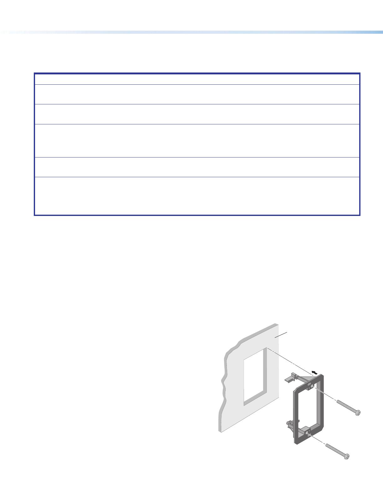
To prepare the site:
1. Using the size of the junction box or mud ring for reference,
cut the hole in the mounting surface. Protect the surface
prior to and during cutting so the surface is not
damaged.
2. Run cables to the mounting location, leaving enough
slack for device installation.
3. Install the junction box or mud ring into the wall or
furniture.
4. Secure the cables with a clamp for strain relief and so
they do not slip back down into the wall or furniture.
Rev. D: added a checklist
item for the 802.1X
certificate and key.
Rev. C: Changed French text in the
second Attention
Rev. C: Changed the note to an
Attention & added French text,
per Homi As requirement for
the HC products..
Rev. D: Updated
links for the
ADA reference
documents.
Wall
Mud Ring
Figure 6. Installing a Mud Ring
5
Step 3: Change Buttons, a Bezel, or Wallplate (optional)
If desired, replace the wallplate, bezel, and rotary encoder knob (NBPVC1D); or replace one or more buttons or button pairs
using available additional buttons. Optional button kits are available in various languages. Wallplates and bezels are available in
black, as well as white. For the NBPVC1D, the rotary encoder knob must be removed in order to replace buttons.
NOTE: A custom button builder tool is available at https://www.extron.com/article/custombuttonbuilder where you can
order custom-labeled buttons for the NBP.
The bezel must be removed to access buttons.
To replace the buttons or bezel:
1. For the NBPVC1D only, remove the rotary encoder knob (see “Removing the knob (NBPVC1D)” on the next page).
2. If already installed, remove the wallplate. Save the two screws for later use.
3. Remove the bezel as follows:
a. Insert the tip of a small, flat-bladed screwdriver (such as
an Extron Tweeker) through one of the slots at the top or
bottom of an NBP, as shown at right in figure 7.
b. Angle the screwdriver to press gently down on the tab to
release and pry the bezel from the mounting plate.
c. If the bezel has not fully detached from the mounting
plate, repeat steps 3a and 3b with the hole and tabs at the
opposite end of the mounting plate.
d. Lift the bezel away from the mounting plate.
4. Remove any buttons to be replaced as follows:
a. Press the button or button pair from the front of the bezel
out through the back of its bezel opening. If necessary, pull
the buttons out gently from the back.
NOTE: The smaller buttons are arranged in pairs
connected by a rubbery membrane.
b. If you are replacing the bezel, repeat step 4a until all
buttons are removed.
c. Set the removed buttons aside for later use.
5. Insert a button or button pair as follows:
a. Insert a new button or button pair from the back into the
appropriate opening in the original or the replacement bezel.
b. Align the two pegs in the upper left and lower right corners of
the button or button pair (see figure 8) with the corresponding
holes in the bezel. Press the button or buttons into the bezel
so the buttons and pegs are seated into the holes and bezel
opening.
c. Repeat steps 5a and 5b for any additional buttons to be
replaced or installed.
LAPTOP
HDMI
PC
MEDIA PLAYER
VIDEO
e
e
e
e
R
Bezel
Module
NBP 105 D
Press tab down.
Tilt screwdriver to
release bezel from
circuit board.
Figure 7. Using a Screwdriver to Release the
Bezel Tabs, Rear View
OFF
ON
Pegs (2)
Figure 8. Inserting Buttons
6
Network Button Panel — Decorator-Style Series • Setup Guide (Continued)
6. Reattach the original bezel or attach the replacement bezel to the
unit as follows:
a. Align the tabs (at the top and bottom) and pegs (at the
upper left and lower right corners) on the back of the bezel
with the slots and holes on the front of the mounting plate.
b. Gently but firmly press the bezel against the mounting plate
until the tabs and pegs are inserted into the slots and holes,
and the tabs click into place.
Removing the knob (NBPVC1D)
The NBPVC1D has a rotary knob for volume control. Before
replacing buttons, remove the knob, as shown here.
1. Turn the knob (figure10, 1) to expose the hex screw
(see A) holding the knob in place.
2. Insert the provided 0.05inch Allen wrench and turn the
wrench in the direction shown (2) to loosen the screw.
3. Pull the knob straight out to remove it.
Once the knob is removed, the wallplate and bezel can
be removed and the buttons replaced as described in the
preceding sections.
NOTE: To replace the knob, align the knob and press it
straight down onto the rotary shaft, then use the Allen
wrench to gently tighten the hex screw to secure the knob
to the unit.
Step 4: Cable All Devices
1. Connect the NBP to the network (see Rear Panel Features on page3), and cable devices to the control processor (see
the user guide for the appropriate device).
2. Connect power cords and power on the control processor or receiver and other devices.
e
e
e
e
R
LAPTOP
HDMI
PC
MEDIA PLAYER
VIDEO
Bezel
Module
NBP 105 D
Figure 9. Aligning and Reattaching the Bezel
VOLUME
MUTE
1
2
A
Turn the knob to
expose the screw.
Use an Allen wrenc
h
to loosen the screw.
Hex
Screw
Figure 10. Removing the Knob From an NBPVC1D
Rev. D: Removed
reference to HCR.
7
Step 5: Set Up the NBP for Network Communication
1. Ensure that the PC you will use for setup and the
NBP button panel are connected to the same Ethernet
subnetwork.
2. Start Toolbelt and use it to set the DHCP status or to set
the IP address, subnet, gateway IP address, DHCP status,
and related settings. Use the flowchart at right as a guide
to setting up the unit for network use.
NOTES:
If using a host name instead of an IP
address, the user must enter a qualified host
name (Username.HostName.Domain).
For example: somename.somedomain.
com.
If using 802.1X security, see the Extron
802.1X Technology Reference Guide and the
Toolbelt Help file for additional details on
system setup.
Step 6: Configure the System
Use Global Configurator (GCPlus or GCProfessional) to configure the control processor. Alternatively, use Global Scripter or the
ControlScript deployment utility to program the control processor. That configuration sets the control and monitoring behavior for
all the AV devices and control accessories (such as the NBP button panels) in the system. An outline of the main configuration
and programming steps is included in the user guide for the control processor.
NOTE: See the Toolbelt Help File, Global Configurator Help File, Global Scripter Help File, or ControlScript Deployment Utility
Help File as needed for step-by-step instructions and detailed information. The help file for GC includes an introduction to
the software, and how to start a project and configuration.
When configuration or programming is completed, save the project or program script, then build and upload the system
configuration to the control processor.
Step 7: Test and Troubleshoot
1. Test the system. See the user guide for the control processor for an outline of the system testing and troubleshooting
procedure.
2. Make adjustments to wiring or configuration as needed. Remember that the rear panel port on the button panel is not
accessible after the NBP is mounted.
Step 8: Complete the Physical Installation
Mount the unit to a wall or furniture (see Mounting on the next page).
Open the Toolbelt software.
Start Device Discovery.
Toolbelt displays a list of all Extron control devices
connected to the network.
Using the MAC address, locate the desired device
in the list and select it. Enter credentials, if needed.
Network Communication Setup
Connect the NBP and PC to the same network.
Apply power to all devices.
Use the Set IP feature in Toolbelt or
use the Toolbelt Manage > Network Settings tab
feature either to enable DHCP or to enter the
IP address, subnet address, and gateway, then
congure other network settings as needed.
Figure 11. Network Setup
Rev. C: Added
“Enter
credentials, if
needed” and
“enable DHCP
or to...” to the
network setup
flowchart.
Rev. D: Added bullet
point to NOTE box
about 802.1X reference
material.
Rev. D: Made the references to
control processors more generic,
added mentions of ControlScript.
8
Network Button Panel — Decorator-Style Series • Setup Guide (Continued)
Mounting
NOTES:
Extron recommends taking safety
precautions to avoid electrostatic
discharge issues during installation
For best results, Extron recommends
grounding the NBP if the junction box
or mud rings are not already grounded
(see the instructions in the user guide).
Mount the NBP as follows:
1. Insert the cabled NBP into the mud ring
or junction box within the wall or furniture,
aligning the mounting holes
in the NBP mounting tabs with those in box
or mud ring.
2. Secure the NBP to the junction box, wall
or surface mounting box, or mud ring as
follows (see the figures at right):
a. Insert the included screws through the
mounting holes at the top and bottom
of the unit and into the corresponding
threaded holes in the box or mud ring.
b. Using a Phillips screwdriver, lightly
tighten the screws until snug.
ATTENTION:
Do not overtighten the screws.
Veillez à ne pas trop serrer les
vis.
3. Attach the wallplate to the NBP: insert the
included screws through the circular holes in
the wallplate and the tabs on the NBP (see
figures at right). Tighten the screws using a
flat bladed screwdriver until snug.
LAPTOP
HDMI
PC
MEDIA PLAYER
VIDEO
e
e
e
e
R
Wall
Mud Ring
NBP 105 D
Wallplate
Figure 12. Installing the NBP in a Mud Ring
LAPTOP
HDMI
PC
MEDIA PLAYER
VIDEO
e
e
e
e
R
Wallplate
Wall
Electrical
Junction
Box
NBP 105 D
Figure 13. Installing the NBP in a Junction Box
Rev. D: Added note
about grounding
the NBP (from
user guide).
Rev. D: For both
mounting images
added and
revised insertion
lines.
9
Reset Modes: a Brief Summary
The NBP Series button panels offer the following reset modes:
Use Factory Firmware: Press and hold the Reset button while applying power to the unit. Keep holding the button
down until the Reset LED blinks twice, or for 6 seconds, then release the button. The unit enters
factory firmware mode. Use this mode to revert to factory firmware in the event of a firmware
failure.
Do not continue to operate the unit using the factory rmware version. If you want to use the
factory default rmware version, you must upload that version again.
Toggle DHCP Client: Press the Reset button five times (consecutively). Release the button. Do not press the button
within 3seconds following the fifth press. Use this mode to enable or disable the DHCP client
for the LAN port.
The Reset LED blinks 6 times if the DHCP client is enabled.
The Reset LED blinks 3 times if the DHCP client is disabled.
NOTES:
By default DHCP is off and the unit uses a static IP address.
When you disable the DHCP client by using this mode, the unit reverts to using the
previously-set static IP address.
Reset Network Settings: Press and hold the Reset button for 6 seconds. After the Reset LED blinks twice, release and
momentarily press the Reset button. Use this mode to reset all network settings to factory
default values without affecting user-loaded files.
Full Factory Reset: Press and hold the Reset button for 9 seconds. After the Reset LED blinks three times, release
and momentarily press the Reset button within 1 second. Use this mode to return the unit to
factory default settings.
For detailed information on each mode and its use, see the Network Button Panels User Guide at www.extron.com.
Resources
Obtaining Instructions, Information, and Assistance
If you have questions during installation and setup, call the ExtronS3 Sales & Technical Support Hotline or the ExtronS3
Control Systems Support Hotline (1.800.633.9877).
Locating Software and Firmware on the Extron Website
There are three main ways to find software and firmware within www.extron.com:
Via links from the web page for the specific product
Via the Download page (Click on the Download tab at the top of any page within the website.)
Via links from search results
NOTES:
For some software you have the option to click the Download Now button to begin downloading the software file. For
other software there is a link for contacting an Extron support representative who can provide you access to the latest
version.
To obtain Extron control product software, you must have an Extron Insider account. Extron provides training to our
customers on how to use the software. Access to the full features of Global Configurator Professional is available to
those who successfully complete Extron Control Professional Certification.
10
Network Button Panel — Decorator-Style Series • Setup Guide (Continued)
© 2018-2023 - Extron Electronics All rights reserved. www.extron.com
All trademarks mentioned are the property of their respective owners.
Worldwide Headquarters: Extron USA West, 1025 E. Ball Road, Anaheim, CA 92805, 800.633.9876
68-3267-50, Rev. D
08 23
Overall Configuration Procedure
Step 5: Configure the IP settings of each
NBP and of the control processor.
See the network
communication
setup instructions
Create a new GC Professional or GC Plus project
and add the control processor to it.
Congure ports.
Add NBP button panels and congure the buttons.
Step 7: Test the system,
make adjustments, nalize conguration.
Save the project.
Step 4: Cable the NBPs and the control processor,
then apply power.
Cable all other devices.
Step 2: Prepare the installation site.
Step 1: Get ready.
Step 3: Change buttons or faceplates, if desired.
Step 8: Mount the NBPs.
Create monitors, schedules, timers, macros,
and local variables.
Build and upload the conguration to
the control processor.
If desired or required, install a new
security certicate (via Toolbelt).
Within Global Configurator
(GC Professional or
GC Plus mode):
Step 6
Figure 14. Overall Configuration Steps
network
communication
setup instructions
on page 7.
For information on safety guidelines, regulatory compliances, EMI/EMF compatibility, accessibility, and related topics, see the
Extron Safety and Regulatory Compliance Guide on the Extron website.
  • Page 1 1
  • Page 2 2
  • Page 3 3
  • Page 4 4
  • Page 5 5
  • Page 6 6
  • Page 7 7
  • Page 8 8
  • Page 9 9
  • Page 10 10

Extron NBP 108 D Installation guide

Type
Installation guide
This manual is also suitable for

Ask a question and I''ll find the answer in the document

Finding information in a document is now easier with AI

in other languages