Page is loading ...

Z-Wave® USNAP®
Module User Guide
The RTZW-02 USNAP module is a plug in
module that adds Z-Wave® functionality to a
CT-Series Thermostat [CT= Communicating
Thermostat].
The CT-Series Thermostat with an RTZW-
02 module is compatible with a broad range
of Z-Wave® certied devices from other
manufacturers and can be controlled wirelessly
with Z-Wave® controllers supporting the
Thermostat General V2 Device Class. Please
consult the user manual and your controller supplier for more details.
The RTZW-02 provides two-way communication as part of a Z-Wave®
network. When it receives commands from Controller device, it sends
back conrmation that the command was received and implemented. Each
module in a Z-Wave® network communicates with every other module,
acting as a “repeater” and routing your commands to their destination
514-001-000

PG 2
by the most reliable pathway. When Z-Wave® devices (regardless of
manufacturer) are installed throughout the house, signals are automatically
routed around obstacles or dead spots, strengthening the network as more
devices are added.
The Basics
The RTZW-02 USNAP module is designed to be inserted into an empty
USNAP slot in any CT-Series Thermostat. (Follow the instructions that come
with your CT-Series Thermostat and install it to your HVAC system before
installing the RTZW-02 USNAP module.)
Note: Some
models of the
CT-Series are
capable of
operating in
battery only
mode (i.e. without
C-wire from
HVAC system),
yet some other

PG 2
models of the CT-Series (like the CT-80) are only capable of working in your HVAC
system with the C-wire present.
The RTZW-02 USNAP module is designed to work with either constant present
power in the thermostat (ie C-wire), or it can run only on batteries when no
C-wire is present. Depending on which model CT-Thermostat you have, and
how your CT-Thermostat is powered will determine which functionality the
RTZW-02 module will have when added to a Z-Wave® network.
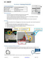
Getting Started
Examine your CT-Thermostat and identify an empty USNAP slot (refer to your
CT-Thermostat instruction manual for details).
1) Power OFF the thermostat by removing batteries and disconnecting the C wire.
2) Insert the RTZW-02 module into the CT-Thermostat Radio Slot with the label on the
RTZW-02 facing the wall behind the thermostat. The RTZW-02 module should slide in
and engage with no visible protrusion from the thermostat.
3) Power up the thermostat by re-installing the batteries and re-connecting the C wire.
4) Press the reset button on your CT (see thermostat documentation) and reset the CT
by pressing the reset button for 1 second.

PG 4
During reset you should see the “radio tower” icon appear on your CT along
with some beeps indicating that the CT Thermostat is initializing the RTZW-
02 USNAP module. When the beeping nishes (about 10 seconds), your CT
Thermostat will be ready to join and be controlled by a Z-Wave® network.
Join or Un-Join Network
1) Set your primary controller to INCLUSION mode to add the thermostat as a
node on your network (see your specic controller’s User Manual for detailed
instructions).
2) Press/Touch the Mate Button. This will bring you to the network inclusion
screen.
Mate button: On touch screen units the MATE button is on the MENU
screen. On other LCD thermostat’s see thermostat instructions for mate
button location.
3) If you only have 1 USNAP module inserted in the thermostat you will see
a r1 or r2 to indicate that the radio is in slot 1 or slot 2. If you have multiple
radios you can select which radio you want to join the network by selecting an
r1 or r2 from the top left hand corner of the screen. When you have selected a
radio, the large r1 or r2 will appear in the center of the screen.

PG 4
4) When the radio is selected and the large r1 or r2 is on the center of the
screen, press the mate button, this will initiate the inclusion process. When
a device has has been successfully included into the network the icon LINK
will appear under the radio tower. Similarly, when you are trying to exclude
the device from the network, the icon LINK will disappear when the node has
successfully left the network.
Your controller will indicate the thermostat was successfully added to its
network (see your specic controller’s User Manual for details.)
For other controller specic tasks such as adding the thermostat to Scenes or
Groups, or excluding the thermostat as a node, use the mate button to activate
the Z-Wave® signal needed for inclusion or exclusion.
Operation
See your specic controller’s User Manual for detailed instructions on
operating your thermostat. If your controller supports full thermostat device
class functions then the following remote features are available:
a) Up and Down Temperature Control
b) Change between HEAT and COOL modes
c) Read the current temperature
d) Set/Read the indicator

PG 6
d) Set/Read the Fan mode
e) Set/Read the clock (on certain CT models only)
f) Set/Read the user display area (on certain CT models only)
Battery Power
When your thermostat is running on battery power, the Z-Wave® radio will
turn off to help conserve battery life. The RTZW-02 Z-Wave® radio module
supports Z-Wave® beaming, which allows other devices in the network to wake
up the RTZW-02 and accept commands, and then go back to sleep.
C-Wire Power
When your thermostat is running on C-Wire power, the Z-Wave® radio will stay
on and actively help in routing messages within the Z-Wave® network.
Simple Mode/Normal Mode
The most RTCOA Touchscreen thermostats offer two modes of operation,
Normal Mode and Simple mode. Normal mode is intended for use as a stand
alone programmable thermostat. In Normal mode the user can program the
thermostat to change temperatures at various points throughout the day.
Simple mode is intended for use with a larger control system - like an alarm
system or home automation system. Simple mode is meant to run a single
temperature constantly. This temperature can be set locally on the thermostat,

PG 6
or remotely using a Z-Wave® USNAP module. See the thermostat instruction
book for how to enter simple mode
Factory Default Restore
Performing a Factory Default Restore will return your thermostat to the state
it was in when it left the factory. This means that all of its conguration and
parameters will be returned to their default values. This includes resetting its
Z-Wave network information, removing it from its previous network. This action
should only be used in the event that the network primary controller is missing
or otherwise inoperable. To perform this action, the thermostat must be switch
to OFF mode. Wait until the radio wave icons on the left side of the screen stop
blinking then touch the screen once to turn on the back light and then hold the
center of the screen for about 8 seconds until the thermostat beeps.
Behavior Note: When power is rst applied to this device it will broadcast
a Hail message followed by a Node Information frame. This behavior is to
maintain backwards compatibility with older controllers
that work with this line of devices.

PG 8
Advanced Z-Wave® Information
The RTZW-02 supports compliant mapping of the Z-Wave® BASIC_
COMMAND_CLASS to the CT thermostat “Energy Saving” and “Comfort
Mode” as follows:
Basic Set (Value = 0x00) = Set Energy Saving Mode
Basic Set (Value = 0x01-0x63 & 0xFF) = Set Comfort Mode
Energy Savings applies a 4o F setback to the existing set point temperature to
comply with EPA recommendations for energy savings.
Association group:
This device support one association group, and up to two nodes in that group. If at
least one node is added to association group one (1), the thermostat will send the
following association reports when the respective state has changed:
• Thermostat Mode Report
• Thermostat Operating State Report
• Fan Mode Report
• Fan State Report
• Setpoint Report (for all supported setpoints)
• Sensor Multilevel Report (if enabled by Conguration Command Class)
The association command class can be congured to send encapsulated reports

PG 8
via the Multi Instance Command Class or the Multi Channel Command Class. If the
association conguration commands are sent inside encapsulated commands, the
thermostat will respond with encapsulated reports of the same type (Multi Instance
v1 or Multi Channel v3). Encapsulation is the only way to congure the thermostat to
send humidity sensor multilevel association reports.
For example, if an Association Set is encapsulated in a Multi Channel Command
Encapsulation command is sent to the humidity instance (2), then the thermostat will
encapsulate all un-solicited humidity sensor multilevel reports in the Multi Channel
Command Encapsulation Command. The default instance is the temperature instance
(1). If the Association Set is sent un-encapsulated then the thermostat will send all un-
solicited temperature sensor multilevel reports unencapsulated.
All association reports other than the humidity multilevel are in the default instance (1).
The thermostat will encapsulate the association reports based on the last Association
Set encapsulation type received (i.e. un-encapsulated, Multi Instance v1, or Multi
Channel V3).
Anti-theft:
The Anti-theft Command Class is used to disable a subset of supported/controlled
command classes in the thermostat if the thermostat is being excluded and re-
included into a Z-Wave network again. The thermostat supports version 2 of the
Anti-theft Command Class. This command class is typically used when installing
a thermostat in a public location such as a hotel room or conference center. The
command class allows the user to lock the thermostat to the actual Z-Wave network

PG 10
and to render it useless if it is removed from the local network without being unlocked.
Another application would be to protect service provider owned products from leaving
the service providers network before they are paid for.
The following command classes are disabled when Anti-theft protection is engaged:
Basic Command Class
Clock Command Class
Indicator Command Class
Manufacturer Specic Command Class
Muiltilevel Sensor Command Class
Thermostat Mode Command Class
Thermostat Operating State Command Class
Thermostat Fan Mode Command Class
Thermostat Fan State Command Class
Thermostat Setpoint Command Class
Version Command Class
Conguration Command Class
Battery Command Class
Association Command Class
Anti-theft Command Class
Multi Channel Command Class*
* Only supported if a humidity sensor is present.

PG 10
Conguration Parameters:
This device supports the following conguration parameters:
Parameter Name Set/Get Default Values
1 Temp Reporting Threshold Set/Get 2 0 to 4
2 HVAC Settings Get Only N/A see
details
3 Utility Lock Enable/Disable Set Only 0
4 C- Wire/Battery Status Get Only N/A 0 or 1
5 Humidity Reporting
Threshold
Set/Get 2 0 to 3
6 Auxiliary/Emergency Set/Get 0 0 or 1
7 Thermostat Swing Temp Set/Get 2 1 to 8
8 Thermostat Diff Temp Set/Get 4 4 to 12
9 Thermostat Recovery Mode Set/Get 2 1 or 2
10 Temp Reporting Filter Set/Get
see
details
11 Simple UI Mode
Enable/Disable Set/Get 1 0 or 1
12 Multicast Enable/Disable Set/Get 0 0 or 1
0 to 127

PG 12
1. Temperature Reporting Threshold (8-bit)
This value determines the reporting threshold when association reporting is enabled.
Unsupported values will be ignored.
2. HVAC Settings (32-bit)
Byte 1 = HVAC Setup: Normal (0x01) or Heat Pump (0x02)
Byte 2 = Aux Setup(Gas (0x01) or Electric (0x02)) & Number of Auxiliary Stages (Heat
Pump)/Number of Heat Stages (Normal)
Byte 3 = Number of Heat Pump Stages
Byte 4 = Number of Cool Stages
3. Utility Lock (8-bit)
If set to 0, the utility lock is disabled, all other values, 1-255, will enable the utility lock.
4. C-Wire/Battery Status (8-bit)
If 0x01, the thermostat is being powered form a C-wire, if 0x02, the thermostat is
being powered off of batteries.

PG 12
5. Humidity Reporting Threshold (8-bit)
This value determines the reporting threshold when association reporting is enabled.
Unsupported values will be ignored.
6. Auxiliary/Emergency Enable/Disable (8-bit)
If set to 0, auxiliary / emergency heat is disabled, all other values, 1-255, will enable
the auxiliary / emergency heat. This can only be enabled when the thermostat is set to
Heat Pump mode.
7. Thermostat Swing Temperature (8-bit)
The thermostat swing temperature is in units of 0.5 degrees Fahrenheit. A value of
0x01 is 0.05F and 0x02 is 1.0F. The supported values may vary from thermostat to
thermostat but typically the allowed values are 0.5F (0x01) to 4.0F (0x08).
8. Thermostat Differential Temperature:
Thermostat Differential Temperature Set Command Denition
7 6 5 4 3 2 1 0
Command Class = COMMAND_CLASS_CONFIGURATION
Command = CONFIGURATION_SET
Parameter = 0x08
Default RESERVED Size = 0x02
Thermostat Differential Mode
Thermostat Differential Temperature
The conguration report returns both heat and cool differential temperatures.

PG 14
Thermostat Differential Temperature Report Command Denition
7 6 5 4 3 2 1 0
Command Class = COMMAND_CLASS_CONFIGURATION
Command = CONFIGURATION_REPORT
Parameter = 0x08
Thermostat Heat Differential Temperature
Thermostat Cool Differential Temperature
Parameter (8-bit)
The parameter is set to 8 for the thermostat differential temperature.
Default (1-bit)
If the default bit is set, the thermostat heat differential temperature will be set to 2.0
degree Fahrenheit.
Size (3-bit)
The Size eld must be set to 2 (010b).
Thermostat Differential Mode (8-bit)

PG 14
The Thermostat Differential Mode determines which differential temperature to set.
Valid values are 0x00 (Heat) or Cool (0x01)
Thermostat Differential Temperature (8-bit)
The thermostat differential temperature is in units of 0.5 degrees Fahrenheit. A value
of 0x04 is 2.0F and 0x06 is 3.0F. The differential temperature must be an integer
value. Non-integer values, such as 1.5F (0x03), should not be used. The supported
values may vary from thermostat to thermostat but typically, the allowed values are
2.0F (0x04) to 6.0F (0x0C).
9. Thermostat Recovery Mode (8-bit)
The Thermostat Recovery Mode can be either fast (0x01) or economy (0x02).
10. Thermostat Reporting Filter(16-bit):
Set Command Denition
7 6 5 4 3 2 1 0
Command Class = COMMAND_CLASS_CONFIGURATION
Command = CONFIGURATION_SET
Parameter = 0x0A
Default RESERVED S ize = 0x04
Precision (0x00) S cale B ound Size (0x01)
Temperature Filter Lower Bound
Precision (0x00) S cale B ound Size (0x01)
Temperature Filter Upper Bound

PG 16
Thermostat Reporting Filter Report Command Denition
7 6 5 4 3 2 1 0
Command Class = COMMAND_CLASS_CONFIGURATION
Command = CONFIGURATION_SET
Parameter = 0x0A
Temperature Filter Lower Bound
Temperature Filter Upper Bound
Parameter (8-bit)
The parameter is set to 10 (0x0A) for the temperature reporting lter.
Default (1-bit)
If the default bit is set, the upper bound is zero (0) and the lower bound is 124. This
disables the lter.
Size (3-bit)
The Size eld must be set to 4 (100b).
Precision (3-bits)
The precision eld describes what the precision of the temperature lter value. The lter
must be zero (0x00).
Scale (2-bits)
The scale eld indicates the temperature scale used, 0 indicate the use of the Celsius
temperature scale and 1 indicates use of the Fahrenheit scale.
Bound Size (3-bits)
The size eld indicates the number of bytes used for the temperature lter value. This
eld must be one (0x01).

PG 16
Temperature Filter Lower Bound (8-bit)
The thermostat will report ambient temperature changes for temperature values less than
the lower bound. This eld must be between 0F and 124F. By default, this value is 124F
(report all temperature changes).
Temperature Filter Upper Bound (8-bit)
The thermostat will report ambient temperature changes for temperature values greater
than the upper bound. This eld must be between 0F and 124F. By default, this value is
0F (report all temperature changes).
11. Simple Mode Enable/Disable (8-bit)
If the value is set to 0x00 then Normal Mode is enabled. If the value is set to 0x01 then
Simple Mode is enabled.
12. Multicast Enable/Disable (8-bit)
If set to 0, multicast is disabled, if set to 1, will enable the multicast.

PG 18
FCC and IC Statement
FCC Regulatory Information:
NOTE: This equipment has been tested and found to comply with the limits for a Class B digital device, pursuant to
Part 15 of the FCC Rules. These limits are designed to provide reasonable protection against harmful interference in
a residential installation. This equipment generates, uses, and can radiate radio frequency energy and, if not installed
and used in accordance with the instruction, may cause harmful interference to radio communications. However,
there is no guarantee that interference will not occur in a particular installation. If this equipment does cause harmful
interference to radio or television reception, which can be determined by turning the equipment off and on, the user is
encouraged to try and correct the interference by one or more of the following measures:
a) reorient or relocate the receiving antenna,
b) increase the separation between the equipment and receiver,
c) connect the equipment into an outlet on a circuit different from that to which the receiver is connected.
Consult the dealer or an experienced radio/TV technician for help.
IC Regulatory Information:
This Class B digital apparatus meets all requirements of the Canadian Interference Causing Equipment Regulations.
Operation is subject to the following two conditions: (1) this device may not cause harmful interference, and (2) this
device must accept any interference received, including interference that may cause undesired operation of the device.
Cet appareillage numérique de la classe B répond a toutes les exigences de l’interférence canadienne causant des
règlements d’équipement. L’opération est sujette aux deux conditions suivantes: (1) ce dispositif peut ne pas causer
l’interférence nocive, et (2) ce dispositif doit accepter n’importe quelle interférence reçue, y compris l’interférence qui
peut causer l’opération peu désirée.
WARNING: Changes or modications to this receiver not expressly approved by RTCOA. could void the user’s
authority to operate this equipment.
/