Page is loading ...

OPERATION MANUAL
DIGIFORCE®
Model 9311
Manufacturer:
© 2018
burster
praezisionsmesstechnik gmbh & co kg
burster
praezisionsmesstechnik gmbh & co kg
All rights reserved
Talstr. 1 - 5
P.O. Box 1432
76593 Gernsbach
76587 Gernsbach
Germany
Germany
Valid from:
13.08.2018
Tel.: +49-7224-645-0
Fax: +49-7224-645-88
Email: info@burster.com
www.burster.com
2770-BA9311EN-5170-081526

2 of 216
Warranty disclaimer
All information in the present documentation was prepared and compiled with great care and reproduced
in accordance with effective control measures. This documentation may contain errors, and the
information it contains and the corresponding technical data are subject to change without notice.
Reproduction of any part of this documentation or its processing or revision using electronic systems is
prohibited without the manufacturer's prior written approval.
Components, devices and measurement sensors made by burster praezisionsmesstechnik (hereinafter
referred to as the "product") are the result of targeted development and meticulous research. From the
date of delivery, burster provides a warranty for the proper condition and functioning of these products
covering material and production defects for the period specified in the warranty document accompanying
the product. However, burster waives any guarantee or warranty obligations or any additional liability for
consequential damages caused by improper use of the product, in particular the implied guarantee of
success in the market as well as the suitability of the product for a particular purpose. Furthermore,
burster assumes no liability for direct, indirect or incidental damages or for consequential or other
damages arising from the provision and use of the present documentation.
Trademark information
1-Wire® is a registered trade mark of Maxim Integrated. All brand names or trademarks mentioned in this
document refer solely to the products concerned and are the property of their respective owners. By
mentioning these trademarks, burster praezisionsmesstechnik gmbh & co kg is not laying claim to
trademarks other than its own.

3 of 216

4 of 216
Contents
1 For your safety ........................................................................................................................................... 9
1.1 Symbols used in the instruction manual ............................................................................................. 9
1.1.1 Signal words............................................................................................................................ 9
1.1.2 Pictograms ............................................................................................................................ 10
1.2 Symbols and precautionary statements on the instrument .............................................................. 10
1.2.1 Conventions used in the instruction manual ......................................................................... 10
2 Introduction .............................................................................................................................................. 11
2.1 Intended use ..................................................................................................................................... 11
2.2 Customer Service ............................................................................................................................. 11
2.2.1 Customer service department ............................................................................................... 11
2.2.2 Contact person ...................................................................................................................... 11
2.3 Download the test certificate ............................................................................................................. 11
2.4 Ambient conditions ........................................................................................................................... 12
2.4.1 Storage conditions ................................................................................................................ 12
2.4.2 Operating conditions ............................................................................................................. 12
2.4.3 Restrictions on use ............................................................................................................... 12
2.4.4 Cleaning ................................................................................................................................ 13
2.5 Personnel .......................................................................................................................................... 13
2.6 Contents of pack ............................................................................................................................... 13
2.7 Unpacking ......................................................................................................................................... 14
2.8 Warranty ........................................................................................................................................... 14
2.9 Conversions and modifications ......................................................................................................... 14
2.10 Error messages when the unit is powered up .................................................................................. 15
3 Principles of design and operation ....................................................................................................... 16
3.1 Range of functions ............................................................................................................................ 16
3.2 Versions ............................................................................................................................................ 16
3.3 Power supply .................................................................................................................................... 17
3.4 Sensors suitable for use with the instrument .................................................................................... 17
3.4.1 Automatic sensor identification (burster TEDS) .................................................................... 18
3.5 Recording measurement curves ....................................................................................................... 18
3.5.1 Starting / stopping a measurement ....................................................................................... 18
3.5.2 Sampling the measurement signals ...................................................................................... 19
3.5.3 Defining an X-axis reference ................................................................................................. 19
3.6 Evaluation methods .......................................................................................................................... 20
3.7 Tare function ..................................................................................................................................... 20
3.8 Sensor test ........................................................................................................................................ 21
3.9 Online switching points ..................................................................................................................... 21
3.10 Visualizing, signalling and transferring results .................................................................................. 21
3.11 Configuration tools ............................................................................................................................ 22
4 Controls and connections ...................................................................................................................... 23
4.1 Front panel ........................................................................................................................................ 23

5 of 216
4.2 Rear of instrument ............................................................................................................................ 24
4.3 Touch control .................................................................................................................................... 25
4.4 Controls and symbols ....................................................................................................................... 26
4.5 Earthing and shielding ...................................................................................................................... 27
4.6 Connections ...................................................................................................................................... 28
4.6.1 PLC I/O signals ..................................................................................................................... 28
4.6.2 Connector A – Potentiometer, Standard signal .................................................................... 30
4.6.2.1 Connector A: connecting potentiometric sensors.................................................. 31
4.6.2.2 Connector A: connecting potentiometric sensors fitted with burster TEDS .......... 31
4.6.2.3 Connector A: connecting standard-signal sensors ............................................... 31
4.6.2.4 Connector A: connecting standard-signal sensors fitted with burster TEDS ........ 32
4.6.3 Connector B – strain gage sensors, standard-signal sensors .............................................. 33
4.6.3.1 Connector B: connecting strain gage sensors without sense leads ..................... 34
4.6.3.2 Connector B: connecting strain gage sensors without sense leads, fitted with
burster TEDS ......................................................................................................... 34
4.6.3.3 Connector B: connecting strain gage sensors with sense leads ........................... 34
4.6.3.4 Connector B: connecting strain gage sensors with sense leads, fitted with
burster TEDS ......................................................................................................... 35
4.6.3.5 Connector B: connecting standard-signal sensors ............................................... 35
4.6.3.6 Connector B: connecting standard-signal sensors fitted with burster TEDS ........ 35
4.6.3.7 Connector B: connecting a piezoelectric sensor (option) ...................................... 36
4.6.4 USB service port ................................................................................................................... 37
4.6.5 Ethernet port ......................................................................................................................... 37
4.6.6 USB host port (memory-stick data logging) .......................................................................... 37
4.6.7 PROFIBUS interface ............................................................................................................. 38
4.6.8 Ethernet-based Fieldbus interface (dual RJ45) .................................................................... 38
4.6.9 Instrument power plug .......................................................................................................... 38
5 Using the instrument for the first time .................................................................................................. 39
5.1 Panel-mounting................................................................................................................................. 39
5.1.1 Panel-mounting ..................................................................................................................... 39
5.1.2 Panel cutout .......................................................................................................................... 40
5.2 User language and diagnostics ........................................................................................................ 41
6 Configuring the instrument - "Configuration Main Menu" .................................................................. 42
6.1 Basic setup ....................................................................................................................................... 43
6.1.1 Function key definition .......................................................................................................... 44
6.1.2 PLC outputs .......................................................................................................................... 46
6.1.3 PLC inputs ............................................................................................................................ 48
6.1.4 Access permissions .............................................................................................................. 49
6.1.5 Measurement menus ............................................................................................................ 51
6.1.6 Instrument information .......................................................................................................... 52
6.1.7 LCD setting ........................................................................................................................... 52
6.1.8 Date and time........................................................................................................................ 53
6.1.9 Language .............................................................................................................................. 53

6 of 216
6.1.10 Interfaces .............................................................................................................................. 54
6.1.10.1 USB interface parameters ..................................................................................... 54
6.1.10.2 Ethernet interface parameters ............................................................................... 55
6.1.11 Acknowledgement function ................................................................................................... 56
6.1.12 Order sheet ........................................................................................................................... 57
6.1.13 USB flash .............................................................................................................................. 57
6.1.14 Channel settings ................................................................................................................... 62
6.1.15 Diagnostics............................................................................................................................ 63
6.1.16 PROFIBUS settings (option) ................................................................................................. 64
6.1.17 PROFINET settings (option) ................................................................................................. 65
6.1.18 EtherNet/IP settings (option) ................................................................................................. 67
6.2 Program selection ............................................................................................................................. 69
6.3 Program Setup Menu ........................................................................................................................ 70
6.3.1 Channel settings ................................................................................................................... 71
6.3.1.1 Scaling analog sensors (strain gage, potentiometer, standard signal sensors) .... 72
6.3.1.2 Inverting measurement signals ............................................................................. 73
6.3.1.3 Configuring sensors fitted with burster TEDS ....................................................... 73
6.3.1.4 Potentiometric sensors .......................................................................................... 74
6.3.1.5 Sensors that output a standard signal ................................................................... 83
6.3.1.6 Strain gage sensors ............................................................................................... 92
6.3.1.7 Piezoelectric sensors (option) ............................................................................. 101
6.3.2 Measurement mode ............................................................................................................ 106
6.3.2.1 Sampling the measurement channels ................................................................. 107
6.3.2.2 Measurement curve reference............................................................................. 107
6.3.2.3 Curve recording, return point ............................................................................... 112
6.3.2.4 Start/Stop mode ................................................................................................... 113
6.3.3 Configuring the evaluation .................................................................................................. 115
6.3.3.1 Window ................................................................................................................ 115
6.3.3.2 Trapezoid ............................................................................................................. 120
6.3.3.3 Threshold ............................................................................................................. 124
6.3.3.4 Envelopes ............................................................................................................ 128
6.3.3.5 Tolerance band for evaluation elements ............................................................. 130
6.3.4 Online switching points ....................................................................................................... 132
6.3.5 Graphical test operation ...................................................................................................... 134
6.3.5.1 Graphical Test Operation - Zoom (adjust zoom for X/Y graphs) ......................... 136
6.3.5.2 Graphical test operation – AutoSet ..................................................................... 138
6.3.5.3 Graphical Test Operation – Configuring a window .............................................. 140
6.3.5.4 Graphical Test Operation – Configuring a trapezoid ........................................... 145
6.3.5.5 Graphical Test Operation – Configuring a threshold .......................................... 150
6.3.5.6 Graphical Test Operation – Generating an envelope ......................................... 155
6.3.5.7 Graphical test operation – Cursor ....................................................................... 159
6.3.5.8 Graphical test operation – Reference curve ........................................................ 161
6.3.5.9 Graphical Test Operation – Displaying a curve array ........................................ 163

7 of 216
6.3.6 Numerical test operation ..................................................................................................... 165
6.3.6.1 Numerical Test Operation - Live sensor values .................................................. 166
6.3.6.2 Numerical Test Operation – Tare ........................................................................ 168
6.3.6.3 Numerical Test Operation - PLC signals ............................................................. 169
6.3.7 Sensor test .......................................................................................................................... 171
6.3.8 User-defined values ............................................................................................................ 173
6.3.9 USB flash ............................................................................................................................ 176
6.4 Copy programs ............................................................................................................................... 177
6.4.1 Copying a measurement program or sensor settings......................................................... 177
6.4.2 Deleting a measurement program ...................................................................................... 179
6.5 Curve analysis (Viewer) .................................................................................................................. 180
6.5.1 Curve analysis - Selection .................................................................................................. 182
6.5.2 Curve analysis - Zoom ........................................................................................................ 183
6.5.3 Curve analysis - Numerical ................................................................................................. 184
7 Measurement results display - Measurement mode .......................................................................... 186
7.1 Top-level view of measurement results .......................................................................................... 186
7.1.1 Global header ..................................................................................................................... 187
7.1.2 Status/error indicator in measurement mode ..................................................................... 187
7.1.3 Overall result of last measurement ..................................................................................... 188
7.1.4 Individual evaluation status in measurement mode............................................................ 188
7.2 M1 Graphical measurement curve ................................................................................................. 189
7.3 M2 General curve data ................................................................................................................... 190
7.4 M3 Total result ................................................................................................................................ 191
7.5 M4 Entry/Exit .................................................................................................................................. 192
7.6 M5 User defined values .................................................................................................................. 192
7.7 M6 Statistics ................................................................................................................................... 193
7.8 M7 Order sheet ............................................................................................................................... 194
8 Signal timing diagrams ......................................................................................................................... 195
8.1 Selecting a measurement program ................................................................................................ 195
8.1.1 Changing the measurement program without program acknowledgement ........................ 195
8.1.2 Changing the measurement program with program acknowledgement ............................. 196
8.2 Starting a measurement ................................................................................................................. 197
8.2.1 Measurement without measurement-data logging ............................................................. 197
8.2.2 Measurement with measurement-data logging .................................................................. 198
8.2.3 Measurement using data logging on USB stick (READY control enabled) ........................ 199
8.3 External tare ................................................................................................................................... 200
8.3.1 Without tare warning ........................................................................................................... 200
8.3.2 With tare warning ................................................................................................................ 201
8.4 Online signals ................................................................................................................................. 202
8.4.1 Window evaluation with online signal ................................................................................. 202
8.4.2 Online switching signals S1 to S6....................................................................................... 203
8.4.2.1 Switching signals for X-channel with "Absolute" reference ................................. 203
8.4.2.2 Switching signals for X-channel with "Trigger" reference ................................... 204

8 of 216
8.4.2.3 Switching signals for Y-channel .......................................................................... 205
8.5 Acknowledgement function ............................................................................................................. 206
8.5.1 Example of an NOK evaluation for the following configuration ........................................... 206
8.5.2 Example of an NOK evaluation (without acknowledgement) .............................................. 207
8.5.3 Example of an OK evaluation (without acknowledgement) ................................................ 208
8.6 External actuation of a statistics reset ............................................................................................ 209
8.7 External actuation of a sensor test ................................................................................................. 210
9 Customer Services for your DIGIFORCE® 9311 ................................................................................. 211
10 Technical data ........................................................................................................................................ 212
10.1 Electromagnetic compatibility ......................................................................................................... 212
10.1.1 Interference immunity ......................................................................................................... 212
10.1.2 Interference emission .......................................................................................................... 212
11 Accessories available ........................................................................................................................... 213
11.1 Software .......................................................................................................................................... 213
12 Disposal .................................................................................................................................................. 214
13 Index ....................................................................................................................................................... 215

9 of 216
1 For your safety
The following symbols on the DIGIFORCE® 9311 and in this operation manual warn of hazards.
1.1 Symbols used in the instruction manual
1.1.1 Signal words
The following signal words are used in the operation manual according to the specified hazard
classification.
DANGER
High degree of risk: indicates a hazardous situation which, if not avoided, will result in death or serious
injury.
WARNING
Moderate degree of risk: indicates a hazardous situation which, if not avoided, may result in death or
serious injury.
CAUTION
Low degree of risk: indicates a hazardous situation which, if not avoided, could result in minor or
moderate injury.
NOTICE
Property damage to the equipment or the surroundings will result if the hazard is not avoided.
Note: It is important to heed these safety notices in order to ensure you handle the DIGIFORCE® 9311
correctly.
IMPORTANT: Follow the information given in the operation manual.

10 of 216
1.1.2 Pictograms
Symbol Description
Electric shock hazard
Electrostatic discharge. Do not touch!
Take precautionary measures against static discharge.
Observe the advice for protecting the instrument.
1.2 Symbols and precautionary statements on the
instrument
Symbol Description
Hazard warning
Disconnect the power plug before opening – Follow safety instructions –
Professional servicing only
Warning !
To prevent
electrical shock do
not open device.
Warning of electrical shock hazard
Do not open the unit.
To prevent fire
replace only with
same type and
rating of fuse !
Warning of fire hazard
Always replace the fuse with a fuse of the same type and rating.
1.2.1 Conventions used in the instruction manual
Designation Description
[Fx] Function keys F1 to F3 on the touchscreen display
[Text] Buttons on the touchscreen display
"Term" Terms used in the instrument menus

11 of 216
2 Introduction
IMPORTANT: Read the operation manual carefully before using the equipment, and keep for future
reference.
2.1 Intended use
The DIGIFORCE® 9311 is an instrument that is designed to monitor repetitive production processes. Its
core function is to record and analyse process signals representing physical variables between which
there is a defined relationship, for instance recording a curve of force, pressure or torque plotted against
displacement, angle or time. Graphical evaluation elements such as windows, trapezoids, thresholds or
envelopes are used to analyse the resultant curve. The analysis result is classified as "OK" or "NOK" (Not
OK) and output at various interfaces.
The instrument is NOT intended as a safety device. For instance it is not suitable as an emergency
device for shutting down a press if the pressing force exceeds a threshold value.
2.2 Customer Service
2.2.1 Customer service department
For repair inquiries, please telephone our Service department on +49 7224 645-53, or email:
service@burster.com (Germany only). If you are outside Germany, you should contact your burster agent
(see also www.burster.com).
Please have the serial number to hand. The serial number is essential to establishing the definite
technical status of the instrument and providing help quickly. You will find the serial number on the type
plate of the DIGIFORCE® 9311.
2.2.2 Contact person
If you have any questions relating to the DIGIFORCE® 9311, please go directly to burster
praezisionsmesstechnik gmbh & co. kg, or if outside Germany, please contact your burster agent (see
also www.burster.com.
Head office
burster praezisionsmesstechnik gmbh & co kg
Talstraße 1 - 5
D-76593 Gernsbach
GERMANY
Telephone: (+49) 07224 645-0
Fax: (+49) 07224 645-88
Email: info@burster.de
2.3 Download the test certificate
You have the option to download the test certificate for your DIGIFORCE® 9311 online. To do this, you
need to register at http://www.burster.com/en/registration/. You can then download the test certificate
directly by entering the serial number.

12 of 216
2.4 Ambient conditions
2.4.1 Storage conditions
The following requirements must be met when storing the DIGIFORCE® 9311:
• Store at temperatures between 0 °C and +60 °C
• The unit must be packed in clean packaging
• Store in a dry environment
• No condensation
2.4.2 Operating conditions
The following requirements must be met when operating the DIGIFORCE® 9311:
• Always operate indoors
• Maximum height above sea level 2000 m
• Operate at temperatures between +5 °C and +40 °C, ideally +23 °C
• Humidity: 80% up to +31 °C, decreasing linearly above that temperature to 50% at Tmax, no
condensation
• Class of protection: 1
• Transient overvoltage category: CAT II
• Potential with respect to ground: ≤ 12 VDC between analog ground and ground
• Supply voltage: 100 to 240 VACeff (±10 %), 50 to 60 Hz (±10 %)
Note: Avoid condensation after transportation or storage of the DIGIFORCE® 9311.
2.4.3 Restrictions on use
The DIGIFORCE® 9311 does not pose a hazard if used within its specification and in accordance with the
safety regulations.
The manufacturer does not accept liability for any personal injury or property damage arising from
misinterpretation of measurement results.
Note: The DIGIFORCE® 9311 is not intended as a substitute for safety devices and protective
equipment. Use safety devices and protective equipment.

13 of 216
2.4.4 Cleaning
DANGER
Electrical shock hazard
Disconnect the DIGIFORCE® 9311 from the power plug before cleaning.
Disconnect the DIGIFORCE® 9311 from the power plug and use a slightly damp cloth for cleaning the
unit.
NOTICE
Do not immerse the DIGIFORCE® 9311 in water or hold it under running water. Do not
use strong cleaning agents as these may damage the instrument. Use a slightly damp
cloth to clean the instrument.
2.5 Personnel
Personnel must be familiar with the relevant regulations. They must follow these regulations. Only trained
personnel who are familiar with the applicable safety regulations are permitted to operate the
DIGIFORCE® 9311.
burster is happy to provide your operating personnel with training on the DIGIFORCE® 9311. To find out
more, please look at our range of services at www.burster.com.
2.6 Contents of pack
The following components are supplied:
• DIGIFORCE® 9311
• Operation manual including burster software DVD
• 1 x power lead
• Warranty document
• Test certificate

14 of 216
2.7 Unpacking
DANGER
Electrical shock hazard
Never switch on the instrument if it shows signs of damage incurred in transit. Only
ever use the instrument under the conditions specified in this operation manual.
Inspect the instrument for damage. If you suspect that the unit has been damaged during shipping, notify
the delivery company within 72 hours.
The DIGIFORCE® 9311 should be shipped only in its original packaging or in packaging capable of
providing an equivalent degree of protection.
2.8 Warranty
burster praezisionsmesstechnik gmbh & co kg provides a manufacturer's warranty for a period of 24
months after delivery.
Any repairs required during this time will be made without charge. This does not include damage arising
from improper use.
Please note the following when sending the instrument in for repair:
• If there is a problem with the device, please attach a note to the instrument case
summarizing the fault.
• Technical specifications subject to change at any time without notice.
We also state explicitly that we do not accept liability for consequential damage.
• The instrument must always be dispatched in suitable packaging.
2.9 Conversions and modifications
Note: The warranty shall be deemed void immediately if you open or dismantle the DIGIFORCE®
9311 during the warranty period.
The DIGIFORCE® 9311 does not contain any parts that are intended to be serviced by the user. Only the
manufacturer's own qualified personnel are permitted to open the DIGIFORCE® 9311.
It is not permitted to make any changes to the DIGIFORCE® 9311 without the written agreement of
burster praezisionsmesstechnik gmbh & co kg. burster praezisionsmesstechnik gmbh & co kg does not
accept liability for damages or injury if this condition is disregarded.

15 of 216
2.10 Error messages when the unit is powered up
During boot-up, the DIGIFORCE® 9311 may display certain error messages.
The following errors mean that the DIGIFORCE® 9311 must be sent in for checking and possibly repair:
German error message English error message
"Nichtflüchtige Daten korrupt" "Non-volatile data error"
"Abgleich Fehler" "Calibration error"
"EEPROM von Analogplatine ist leer“ "EEPROM of analog board is empty"
"Fehler beim Lesen der MAC Adresse" "MAC Address Reading Error"
In any of these cases, please call our Service department on (+49) 07224 645-53 or
email: service@burster.com (Germany only). If you are outside Germany, you should contact your burster
agent (see also www.burster.com).
Please refer to the additional guidance on packaging in section 2.7 "Unpacking" on page 14.
If any of the following error messages arise, you must contact our Service department (Germany only). If
you are outside Germany, you should contact your burster agent (see also www.burster.com).
German error message English error message
"Analogplatine wurde getauscht" "Analog board has been exchanged"
"Fehler beim Lesen der Seriennummer" "Serial Number Reading Error"
For further information, please refer to section 2.2 "Customer Service" on page 11.

16 of 216
3 Principles of design and operation
Please refer to the DIGIFORCE® 9311 data sheet for full details of dimensions, weight, degree of
protection etc.
3.1 Range of functions
The DIGIFORCE® 9311 monitors processes in which precisely defined functional relationships need to be
demonstrated between two measured quantities. These measured quantities are recorded synchronously
during the manufacturing process or subsequent functional testing to produce a measurement curve,
which is then assessed using graphical evaluation elements. After evaluating the measurements, the
instrument displays the measurement curve and computed evaluation results on the colour display and
outputs this data at the external control interfaces. A powerful real-time operating system optimizes
processes in the DIGIFORCE® 9311 to achieve an extremely fast evaluation cycle. It typically takes just
25 ms to deliver the global OK or NOK evaluation result, which can then be analysed by a higher-level
controller.
In addition to the traditional evaluation windows with defined entry and exit sides, with the DIGIFORCE®
9311 you can also use thresholds, trapezoids of type X or Y and envelopes as graphical evaluation
elements.
Diagram 1: Block diagram of the DIGIFORCE® 9311
3.2 Versions
Please refer to the data sheet for details of the different versions. You can obtain the latest data sheet
and additional information on the DIGIFORCE® 9311 from http://goo.gl/muUe7D or simply use the QR
code below:

17 of 216
3.3 Power supply
The instrument can be operated with a voltage of 100 to 240 VAC (±10 %) / 50 to 60 Hz (±10 %) / typical
15 VA.
DANGER
Electrical shock hazard
Inspect the power lead for damage before use. Do not connect the power lead if there
are signs of damage.
To help identify damage to the power lead in good time, test it regularly in accordance
with national accident prevention regulations.
3.4 Sensors suitable for use with the instrument
The DIGIFORCE® 9311 can process signals from a huge range of sensor technologies.
Note: The "Channel settings" menu (M21) is where the physical connectors, and hence the particular
sensors, are assigned to the measured curve (X/Y curve); see section 6.3.1 "Channel settings"
on page 71.
The DIGIFORCE® 9311 works with these sensor technologies:
Symbol Type Connector
Strain gage sensors B
Potentiometers A
Sensors with standard signal (process signal) A, B
Piezoelectric (option) B*
*Connector B (Piezoelectric) is available as an option.
Note: There is no strain-gage connection when the optional piezo connection is used.
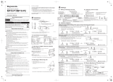
Examples of connected sensors
Diagram 2: Examples of connected sensors

18 of 216
3.4.1 Automatic sensor identification (burster TEDS)
DIGIFORCE® 9311 uses the burster TEDS (Transducer Electronic Data Sheet) to provide automatic
sensor recognition, i.e. the instrument reads the relevant sensor specification from an EEPROM, fitted in
the sensor plug, and can then use this data to perform the necessary channel configuration automatically.
The memory chip in the sensor plug is programmed when the sensor is first ordered or subsequently
calibrated. The burster TEDS feature is only available for sensors with a permanently fitted connecting
lead.
Diagram 3: burster TEDS label
3.5 Recording measurement curves
An external control signal or an internal condition triggers the measurement. On receiving this active start
condition, the DIGIFORCE® 9311 immediately starts writing the values measured by the sensors as X/Y
value pairs to the measured-value memory. The DIGIFORCE® 9311 stops the measurement again when
a stop condition is met.
Then the DIGIFORCE® 9311 immediately evaluates the recorded measurement curve. In this evaluation,
the DIGIFORCE® 9311 checks whether the measurement curve satisfies all the defined graphical
evaluation elements. If so, the measurement is assessed to be OK. If, however, there is at least one
infringement, the DIGIFORCE® 9311 gives the measurement an NOK evaluation.
As soon as it has completed the evaluation, the DIGIFORCE® 9311 refreshes the measurement mode
display and updates the control signals at the PLC interface.
3.5.1 Starting / stopping a measurement
You can use various events as the start signal and stop signal, which can be mutually independent.
Starting a measurement
• External control signal.
• Measured value goes above or below a defined X-value (e.g. a displacement value).
• Measured value goes above or below a defined Y-value (e.g. a force value) (not for
piezoelectric sensors).
Stopping a measurement
• External control signal.
• Measured value goes above or below a defined X-value (e.g. a displacement value).
• Measured value goes above or below a defined Y-value (e.g. a force value).
• Time (timeout).
• Configurable number of recorded measured values reached.

19 of 216
3.5.2 Sampling the measurement signals
DIGIFORCE® 9311 supports three different sampling methods, which you can enable in combination. In
addition to time-based sampling, you can record the pairs of measured values using a configurable
Delta(Δ)X value or Delta(Δ)Y value. This allows the DIGIFORCE® 9311 to use only the optimum number
of sample points to record a curve accurately and to reproduce it in full. For instance, it uses only a very
few points to measure a force/displacement curve that has a low gradient over the initial travel region of
the joining process followed by a steep section as it rises into an end-point force.
Diagram 4: Sampling the measurement signals
3.5.3 Defining an X-axis reference
A measurement curve recorded by the DIGIFORCE® 9311 can be based on a choice of references. For
instance for a force/displacement curve, the reference can be a particular displacement value. In a
conventional application using an "Absolute" reference, the reference point equals the zero point of the
position measurement system. Component tolerances or tolerances in tool changeover systems,
workpiece mounts etc. result in variation (spread) in the X-values of the measurement curves. This
spread might mean that the result from an evaluation element falls in the NOK category. You can
eliminate this spread, however, by using a different reference point.
The DIGIFORCE® 9311 provides the following reference options:
• Absolute
• Final force
• Crossing reference line
• Crossing trigger threshold.

20 of 216
3.6 Evaluation methods
As a universal evaluation tool, the DIGIFORCE® 9311 provides a wide selection of configurable graphical
evaluation elements. These can be used for OK/NOK classification of a vast range of curve types.
In addition to traditional windows with defined entry and exit sides, the DIGIFORCE® 9311 also provides
thresholds, trapezoids of type X or Y and envelopes as graphical evaluation elements. These give you the
extra flexibility you need to evaluate practically any type of signal curve.
You can configure the graphical evaluation elements both by entering numerical values and graphically
using one or more recorded measurement curves.
Summary of the evaluation elements
Symbol Evaluation element Max. number
Window with configurable
entry/exit sides, online signal,
entry/exit, min/max value
3
X or Y trapezoid,
configurable entry/exit side 2
X or Y threshold,
configurable crossing 2
Envelope,
configurable entry/exit side 1
3.7 Tare function
The tare function can be used to correct for static offsets on the sensor channels. For instance you can
correct for a varying background load caused by a tool changeover system by running the tare function
before every measurement. You can also set a warning limit for sensors, which can be used to detect
signs of wear in good time and hence avoid any associated measurement errors. If the current measured
value exceeds the stored warning limit while the tare function is active, the DIGIFORCE® 9311 issues the
"OUT_WARNING_TARE" warning signal.
Options for initiating the tare function
• Manually in the "Numerical test operation" menu (M58)
• Automated trigger via the control interface (PLC I/O or Fieldbus “IN_TARE_X”,
“IN_TARE_Y”, “IN_TARE_X+Y”)
• Automatically when a measurement starts
/