TEAC TC-NSRSP(T)-G3 Compression Load Cell User manual

Type
User manual

TEAC TC-NSRSP(T)-G3 Compression Load Cell is a high-precision device designed to measure compression loads. With its built-in TEDS function, it can automatically calibrate and provide accurate readings when connected to compatible indicators. The rugged construction and resistance to harsh environments make it suitable for various industrial applications.

TEAC TC-NSRSP(T)-G3 Compression Load Cell is a high-precision device designed to measure compression loads. With its built-in TEDS function, it can automatically calibrate and provide accurate readings when connected to compatible indicators. The rugged construction and resistance to harsh environments make it suitable for various industrial applications.

D01313101B
Z
Strain gauge load cell Instructions for Use
TC-NSRSP(T)-G3
Compression Load Cell
Introduction
Thank you for purchasing the TC-NSRSP(T)-G3 load cell.
Please read this document completely before using this
load cell to achieve its best performance and ensure safe
and proper operation.
Included accessories
If anything is missing or damaged, contact the retailer
where you purchased the product.
Test report × 1
Instructions for Use (this document) × 1
oCompany names and product names in this document are the
trademarks or registered trademarks of their respective owners.
IMPORTANT SAFETY INSTRUCTIONS
VWARNING
If something abnormal occurs
Request repair from the retailer where you purchased
the product.
Do not open the cover.
Never remove the cover from this unit. Doing so could
cause malfunction. Request inspection and repair from the
retailer where you purchased the product. Do not alter this
unit. Doing so could cause malfunction.
Do not put foreign objects or water, for example,
into the unit.
Do not place a container that holds water, for example, on
top of this unit. If liquid is spilled, for example, and enters
the unit, this could cause malfunction.
Do not use the unit with any power supply voltage
other than that specified.
Do not use the unit with any power supply voltage other
than that specified. Doing so could cause malfunction.
VCAUTION
Unsuitable installation locations
Do not place the unit in the following types of locations.
Doing so could cause malfunction.
oLocations where it might be exposed to smoke or steam,
such as near a kitchen table or humidifier
oUnstable locations, including unsteady stands and
tilted places
oLocations that are very humid or dusty
oLocations that are exposed to direct sunlight
When not using the unit for a long time
For safety, cut the power supply when not using this unit
for a long time.
Do not operate a damaged unit.
Precautions for use
oThis unit is not built to be water or splash resistant,
and it cannot be used in conditions when the relative
humidity is high. Moreover, use in atmospheres with
corrosive gases should be avoided.
oBe careful to prevent water, oil and other substances
from getting on the unit.
oAvoid use in conditions where condensation could occur.
oConnect cores to the load cell after discharging (elim-
inating) static electricity from your body.
oIf the surrounding temperature changes suddenly,
the values output by this device could become
unstable, making accurate measurement impossible.
(This could occur, for example, in a location blown by
warm or cold air.)
oIf a cable of this unit needs to be bent and shifted, make
the curvature of the bent part at least 50mm. Do not
apply tension to the cable.
oConduct load calibrations periodically.
Installation procedures
oInstall this unit in a place where the structure is level
and can sufficiently bear the load being used.
oScrew holes for attachment are located in two places.
oThe screw dimensions are shown in the table below.
Model Screw size Tightening
torque
TC-NSRSP(T)-G3 M2 (3mm depth) 0.17 N·m
Installation surface
Do not use the
central indentation
as an installation
surface.
Precautions when placing loads on the
unit
oMake sure the load is perpendicular to the surface to
which this unit is attached.
oApply the load so that it is centered on the center of
the unit. If the load is not centered (eccentric load),
twisting, for example, and measurement errors could
occur. This could even result in damage.
F1 F2F
F is the correct load orientation.
F1 is an eccentric inclined load.
F2 is an eccentric load.
oBe careful to avoid turning and twisting from lateral
loads. This could cause troubles like those described
in the previous item.
oBe careful to avoid applying loads that exceed the
rated capacity. In particular, use caution when there are
vibrations because loads that exceed the rated capacity
could occur due to sympathetic vibrations, for example.
oIf the load receiving area (spherical surface) is contacted
by something that is at a different temperature and
the load is increased, the values output by this device
could become unstable, making accurate measurement
impossible. In such a case, wait until the temperature
difference ceases to exist before measuring.
Electrical connection of load cell with
built-in TEDS
oConnect as shown in the illustration below. Incorrect con-
nections could result in inability to balance and in errors
occurring in the output voltage when loads are applied.
Using a cable with bare lead wires
Red Input (+)
Black Output (−)
Blue Input (−)
White Output (+)
Orange TEDS signal (+)
Green TEDS signal (COM)
Shield
TEDS
oThis unit has a built-in TEDS function.
oThe orange and green cores in the cable and the F and
G pins in the connector are wired for TEDS.
oThis unit does not support remote sense.
oSee the operation manuals of indicators and strain
amps that support remote sense for how to connect
sensors with those units.
oThe shield is not connected to the main body of this
product. For this reason, if grounding is necessary because
of external noise, for example, arrange to ground the
shield to a part other than the body of this unit.
oIf output values do not stabilize and are difficult to read
due to external noise or other factors when connected
to an indicator, use the filtering function of the indicator.
oSince the cable is directly connected to this unit, use a
specialized cable when increasing the length. (Please
consult with us.)
oWhen conducting insulation resistance tests, limit them
to the red, black, blue and white cores. Do not apply to
the TEDS cores (orange and green).
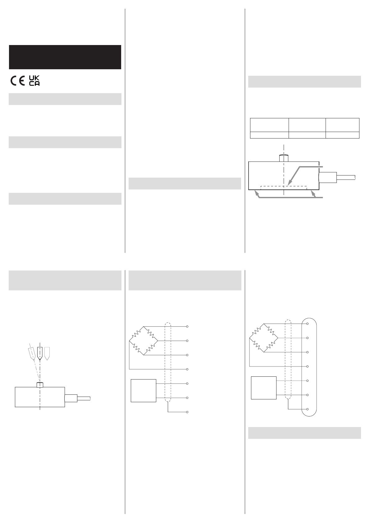
Using a connector (optional)
A Input (+)
B Output (−)
C Input (−)
D Output (+)
F TEDS signal (+)
G TEDS signal (COM)
E Shield
NDIS-compatible connector
TEDS
TEDS overview
TEDS (Transducer Electronic Data Sheet) is a memory chip
that can electronically read and write sensor-specific data.
The TEDS built into this unit has serial number, load cell rated
output and manufacturer name data recorded on it. By
connecting an indicator that supports TEDS, the TEDS data
of the connected load cell will be automatically read and
equivalent input calibration will be completed. (For details,
read the operation manual of the connected indicator.)
Refer to the connection diagrams in “Electrical connection
of load cell with built-in TEDS” as well as the operation
manual for the indicator being connected for procedures
to make connections.
TEAC indicators and signal conditioners that support TEDS
include the TD-01 Portable, TD-700T, TD-260T, TD-9000T
and TD-SC1. For details, inquire at the retailer where you
purchased the unit.
If not using the TEDS function, do not connect the orange
and green load cell cores.
Moreover, take measures to prevent the orange and green
cores from touching other terminals.
Data recorded in TEDS are tested values from calibration
conducted at room temperature during inspection before
shipping from our company.
Load cell output will be affected by the environmental
temperature where used, even when within the compen-
sated temperature range established in the specifications.
Although load cell output is calculated from the calibration
value saved in TEDS, when the environmental temperature
differs greatly from room temperature, the temperature
impacts increase on the zero point and the output. For
this reason, consideration of the effect on output voltage
is necessary. Output voltage changes will be within the
specification range as long as the unit is used at tempera-
tures within the specification range.
When using the TEDS function
This product’s cores for TEDS (orange and green) are
protected by a plastic cover as shown in the illustration.
This is to prevent miswiring and contact with other connec-
tors during use, for example, which could cause shorting.
To use the TEDS function, remove the tip of the plastic cover,
following the perforations, from the end of the cables. Then,
connect the TEDS cores (orange and green) to the indicator.
Refer to “Electrical connection of load cell with built-in TEDS
for how to connect each core.
Cores for sensor
Load cell cable
Protective plastic
Perforations
Cores for TEDS
(orange and green)
When not using the TEDS function
If not using the TEDS function, remove the entire protective
plastic cover and cut off the TEDS cores (orange and green)
around where the plastic cover was attached to the cable.
If you use it without removing these cores, do not remove
the protective plastic or make other arrangements to prevent
the cores from touching other places.
Refer to “Electrical connection of load cell with built-in TEDS
for how to connect each core.
NOTE
Explanations related to TEDS are available on our website.
https://loadcell.jp/en/info/teds.html
ATTENTION
Since the protective plastic and tag are not suitable for
the entire temperature range of this unit’s specifications,
do not expose them to high temperatures.
Handling after use
oWhen moving this unit while it is installed, take protective
measures to prevent it from being shaken or subjected
to excessive external forces.
oWhen storing it, keep it in a dry place where it will not
be exposed to water or oil, for example.
Specifications
TC-NSRSP(T)-G3
Rated capacity: 50N, 100N, 200N, 500N
Safe overload rating: 150% R.C.
Rated output: 1.3mV/V ±30%
Linearity: 0.2% R.O.
Hysteresis: 0.2% R.O.
Repeatability: 0.2% R.O.
Zero balance: ±0.3 mV/V
Safe excitation voltage: 5V
Input terminal resistance: 1150 ±30%
Output terminal resistance: 1150 ±30%
Insulation resistance: 1000MΩ or more (DC 50V)
Compensated temperature range: 0 to 60°C
Permissible temperature range: −20 to 70°C
Temperature effect on zero balance: 0.3% R.O./10°C
Temperature effect on output: 0.3% R.C./10°C
Cable: Ø3mm 6-core shielded robot cable
3m direct connection with bare lead wires
Body material: stainless steel
Environmental compliance: RoHS (10 substances)
Other: built-in TEDS
Dimensional drawings
Dimensions in millimeters (mm)
Ø20
Ø2
Ø4.2
1
SR4
Ø16
2x M2 depth 3
10
Cable
±5º withdrawal
angle tolerance
Rubber sleeve
Warranty explanation
oThe warranty period for this device is one year from
the date of purchase.
oBe aware that repairs will require payment in the following
cases even during the warranty period.
1) Malfunction or damage due to misuse
2) Malfunction or damage caused by modifications or
repairs conducted by any party other than our com-
pany or a service person designated by our company
3) Malfunction or damage caused by dropping, trans-
portation or similar handling after product delivery
4) Malfunction or damage caused by fire, earthquake,
water, lightning or other natural disaster
5) Malfunction or damage caused by external factors,
including power supplies and equipment environ-
mental conditions, that deviate from the operation
requirements of this product
6) Malfunction or damage if the product was not pur-
chased from our company or an agent designated
by our company
oWe offer paid service after the conclusion of the warranty
period. For details, please contact the retailer where you
purchased the unit.
oBe aware that our company will bear no responsibility
for any secondary damages resulting from the operation
of this device or related to data.
oInformation is given about products in this manual
only for the purpose of example and does not indicate
any guarantees against infringements of third-party
intellectual property rights and other rights related to
them. TEAC Corporation will bear no responsibility for
infringements on third-party intellectual property rights
or their occurrence because of the use of these products.
Contact information
TEAC CORPORATION (Manufacturer)
1-47 Ochiai, Tama-shi, Tokyo 206-8530 Japan
Phone: +81-042-356-9154
TEAC AMERICA, INC.
10410 Pioneer Blvd. Suite #1, Santa Fe Springs, California90670,
U.S.A.
Phone: +1-323-726-0303
TEAC EUROPE GmbH. (EU Importer)
Bahnstrasse 12, 65205 Wiesbaden-Erbenheim, Germany
Phone: +49-611-7158-349
TEAC UK Limited (UK Importer)
Luminous House, 300 South Row, Milton Keynes,
Buckinghamshire, MK9 2FR, UK
Phone: +44-1923-797205
0423 MA-2551B
  • Page 1 1
  • Page 2 2

TEAC TC-NSRSP(T)-G3 Compression Load Cell User manual

Type
User manual

TEAC TC-NSRSP(T)-G3 Compression Load Cell is a high-precision device designed to measure compression loads. With its built-in TEDS function, it can automatically calibrate and provide accurate readings when connected to compatible indicators. The rugged construction and resistance to harsh environments make it suitable for various industrial applications.

Ask a question and I''ll find the answer in the document

Finding information in a document is now easier with AI