RCF F 16XR Mixing Console Owner's manual
- Category
- Musical Equipment
- Type
- Owner's manual

HIGH PERFORMANCE PROFESSIONAL
COMPACT LIVE MIXER
MIXER PROFESSIONALE LIVE
COMPATTO AD ALTE PRESTAZIONI
F 16XR
OWNER MANUAL
MANUALE UTENTE

2

3
LANGUAGE
ENGLISH
ITALIANO
4
14

4
IMPORTANT
WARNINGS
SAFETY PRECAUTIONS
Before connecting and using this product, read the instructions provided in this manual carefully and keep it for future reference.
This manual is an integral part of the product and it must accompany it even in the case of changes of ownership, so that the new
owner is aware of the method of installation and use and all safety warnings. Incorrect installation and use of the product shall relieve
RCF S.p.A. of any and all liability.
CAUTION: to prevent the risk of flames or electric shock, do not ever expose this product to the rain or humidity.
1. All warnings, in particular those relating to safety, must be read with special attention, as they contain important information.
2. MAIN SUPPLY FROM THE MAINS
- The supply voltage of the device is sufficiently high to constitute a risk of electric shock to persons: never
install or connect the device with the power supply cable plugged into the mains.
- Before powering this product, make sure that all connections are correct and that the voltage of your mains
supply matches the value on the device data plate; if this is not the case, please contact an RCF dealer.
- The metal parts of the device are earthed via the power supply cable.
- A device with CLASS I construction must be connected to the mains socket with a protective earthing
connection.
- Make sure that the power supply cable of the device cannot be stepped on or crushed by objects, to make
sure it remains intact and in perfect working order.
- To avoid the risk of electric shock, never open the device: there are no parts that can be used by the user
inside.
3. Do not allow objects or liquids to penetrate the product, as this may cause a short circuit. The device must not be exposed to
dripping or splashing water; no naked flame sources (e.g. lighted candles) and no objects filled with liquid (e.g. vases) must be
placed on top of the device.
4. Do not perform any work / modifications / repairs except for those expressly described in this manual. Contact an authorised
service centre or highly qualified personnel when:
- the device is not working (or is working abnormally);
- the power supply cable has been seriously damaged;
- objects or liquids have penetrated the device;
- the device has undergone major knocks.
5. If this product is not used for long periods of time, unplug the power supply cable from the mains.
6. If the product releases abnormal odours or smoke, turn off the power immediately and unplug the power supply cable.
7. Do not connect this product to other devices and accessories not envisaged. Do not try to hang this product using elements
that are not designed or suitable for this purpose. To avoid the risk of falling, do not stack multiple units of this product, unless
this option is expressly specified in the instruction manual.
8. RCF S.p.A. strongly recommends that the installation of this product be carried out only by professional
qualified installers (or specialised installation companies) able to do it properly and to certify installation in
accordance with the applicable regulations in force. The entire audio system must comply with the applicable
rules and regulations regarding electrical systems.
9. Stands and Carts
Where envisaged, the product should only be used on carts or stands recommended by the manufacturer. The device-stand /
device-cart assembly should be moved with the utmost care. Sudden stops, excessive pushing force and uneven or tilted floors
could cause the assembly to overturn.
10. Hearing loss
Exposure to high sound levels can cause permanent hearing loss. The sound pressure level dangerous to one‘s hearing varies
greatly from one person to another and depends on the duration of exposure. To avoid potentially dangerous exposure to high
sound pressure levels, anyone who is exposed to these levels must use adequate protection; when a transducer capable of
producing high sound levels is in use, ear plugs or protective headsets must be worn. See the technical instruction data to find
out the maximum sound pressure levels that the speakers are capable of producing.
11. Place the product away from heat sources and ensure adequate air circulation all around.
12. Do not overload this product for extended periods of time.
13. Never force the controls (buttons, knobs, etc.).
14. Do not use solvents, alcohol, petrol or other volatile substances to clean the external parts of the unit; use a dry cloth.
15. Do not point microphones near and in front of the speakers, so as to avoid any feedback (“Larsen effect”).
NOTE ON CABLES FOR AUDIO SIGNALS
To prevent the occurrence of noise on the cables that carry signals from the microphones or on the line (for example 0 dB), use only
screened cables and avoid laying them in the vicinity of:
- equipment that produces strong electromagnetic fields;
- cables from the power mains;
- speaker lines.
RCF S.p.A. thank you for buying this product, which was made in order to ensure reliability and high performance.
ENGLISH

5
INFORMATION ON THE DEVICE
Thank you for purchasing a RCF mixing console.
F 16XR is a versatile audio mixer equipped with all the tools needed for accurately processing multiple audio signals from a variety of sources.
CLEAR SOUND
RCF mixing consoles devices combine RCF’s professional “sound culture” heritage with innovative design and dedicated manufacturing. RCF mixing
consoles produce clear sound, accurate sound dynamics and extreme versatility of use by passionate audio professionals. RCF mixing consoles are designed
to match perfectly with RCF active speakers.
RELIABILITY
All RCF mixing consoles undergo four extensive instrumental quality tests during construction. A listening test is carried out at the end of production
followed by a final quality control inspection to locate any visible defects, such as scratches or dents. The process guarantees outstanding reliability making
sure that the device you have purchased is of the highest quality.
DESIGN
The unique design of RCF mixing consoles is an example of typically Italian RCF flair and creativity. RCF mixing consoles combine modern, excellent
ergonomic design. In addition to their striking appearance, the original side profile of the mixers makes them easy to grasp securely.
DESCRIPTION AND MAIN CHARACTERISTICS
F 16XR is a versatile analogue audio mixer, equipped with all the tools required for accurate processing of multiple audio signals from different sources.
F 16XR provides an internal PRO DSP FX: the DSP unit offers 16 predefined effects presets: 10 reverbs, 3 delays and 3 modulation effects.
F 16XR AUDIO INPUTS
- CHANNELS 1 to 10: Microphone or Line inputs with separate XLR and TRS jack connectors, three-band EQ with semiparametric Mid. band.
- CHANNELS 9/10 and 11/12: STEREO inputs for LINE level stereo signals (double TRS jack) with three-band equalizer.
- CHANNELS 13/14 and 15/16: STEREO inputs for LINE level stereo signals (RCA or double TRS jack) with three-band equalizer.
F 16XR AUDIO OUTPUTS
- MAIN MIX main stereo output with XLR male connectors (balanced) and TRS jack.
- CONTROL ROOM OUTPUT with TRS balanced jack out connectors.
- 4 AUX OUTPUTS on back panel (Balanced TRS jack).
- 4 BUSSES OUTPUTS on back panel (Balanced TRS jack).
- 1 FOOTSWITCH jack socket (TS jack) for foot control for the activation or deactivation of effects return.
- 1 PHONES headphone outputs (1/4” stereo jack).
- USB audio port for stereo recording and playback to/from dedicated computer.
- Internal PSU 100 V - 240 V, 50-60 Hz, 40 W.
PHYSICAL SPECIFICATIONS
- Dimensions: L = 480 mm, W = 400 mm, H = 110 mm
- Weight: 6,4 Kg
ENGLISH

6
2 2 2 2 2 2 2 2 2 2
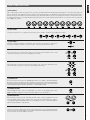
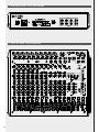
FRONT PANEL
REAR PANEL
25
31 32 33 34 35
1 5
6 7
8
9
10
17 19
22
36 37
38
39
40
ENGLISH
2 2
3
4
20
15
24
26
27
23
21
18
11 13 1412
16
3028 29

7
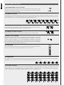
[1] MIC INPUTS
RCF F 16XR provides 10 mono Mic inputs via XLR connectors. The Balanced XLR Microphone preamp input supports sources with a gain range from
0 dB to -50 dB (see section [11] of this manual). All the F 16XR’s MIC-LINE inputs are supplied with an 80 Hz Hi-pass filter. Enable the 80 Hz Hi-Pass
filter when using voice microphone to reduce low frequency pop, bump and rumble noises (see section [11] of this manual). +48 V Phantom Power is
provided for the Mic input: 1 to 8. Enable the Phantom power in presence of Condenser and Electret Microphones or in the event of D.I. box usage (see
section [10] of this manual).
[2] LINE INPUTS
Line inputs TRS jack from 1 to 8 support line signals with a gain of +20 dB to -30 dB (see section [11] of this manual).
[3] LINE INPUT 6
Line Input 6 adds the selectable Hi-Z input feature. The Hi-Z input is very useful when connecting low
level musical instruments like Electric or Acoustic Guitars or Bass Guitars with passive pick-up.
[4] STEREO INPUTS 9/10 AND 11/12
TRS jacks 9/10 and 11/12 provide stereo inputs for line sources. Note that MONO sources can be
connected to jack inputs 9 and 11 (see section [12] of this manual).
[5] STEREO INPUTS 13/14 AND 15/16
RCA and TRS jacks 13/14 and 15/16 provide stereo inputs for line sources. Note that MONO sources
can be connected to jack inputs 13 and 15 (see section [13] of this manual).
[6] FOOTSWITCH
This TS jack connector allows the use of MOMENTARY switches or foot pedals to MUTE and UN-MUTE
the audio coming from the internal FX return. When the FX is muted via footswitch the red LED near
the MUTE button of FX RET fader lights up (see the section [33] of this manual). In this state, the effect
can be unmuted both by pressing the FX MUTE button or the FOOTSWITCH again.
[7] PHONES OUTPUT
Connect headphones here to listen to the MAIN MIX or PFL signals. Set the PHONES LEVEL control
([26]) to minimum (-∞) before connection, and wear headphones to avoid hearing loss.
[8] MAIN OUTPUTS
These XLR male connectors provide +4 dB balanced audio output coming from MAIN MIX. Connect
your main speaker system to XLRs, named L and R. The audio level of MAIN MIX OUT L and R is
controlled by the dedicated MAIN MIX fader (see section [35] of this manual). L and R XLR MAIN MIX
outputs are replicated with L and R TRS jack.
[9] CTRL ROOM OUTPUT
Connect to Control Room Output Balanced jacks a pair of studio monitors as a local listening system. The
audio level of the CTRL ROOM output is controlled by the dedicated CONTROL ROOM potentiometer
on the front panel (see section [24] of this manual).
FRONT PANEL FUNCTIONS
ENGLISH

8
[10] PHANTOM POWER +48 V CH1/6 SWITCH
Dedicated to the Mic input this switch allows the +48 V Phantom Power to the Mic input: 1-8 to be
enabled. Enabling of the Phantom power is necessary only in the presence of Condenser and Electret
Microphones or in case of D.I. boxes usage.
[11] CHANNEL 1 TO 8 GAIN
MIC input (XLR). These controls permit the gain for MIC input to be set with a range from 0 dB to -50 dB. If the LINE INPUT (TRS jack) are in in use the
gain range permitted is from +20 dB to -30 dB. All the F 16XR’s MIC-LINE inputs are supplied with an 80 Hz Hi-pass filter. Enable the 80 Hz Hi-Pass filter
when using microphone for voice to reduce low frequency pop, bump and rumble noises.
2 2 2 2 2 2 2 2
[12] CHANNEL 9/10 AND 11/12 GAIN
MIC input (XLR). These controls permit to the gain for MIC input to be set with a range from 0 dB to
-50 dB. Corresponding LINE INPUT (TRS jack) have a fixed input level gain.
[13] CHANNEL 13/14 AND 15/16 GAIN
STEREO LINE INPUT (TRS jack). The controls allow a gain range control from +20 dB to -30 dB. 2 2
[14] IN USB - IN 15/16 BUTTON
USB IN determines that the stereo audio channels played from an external computer connected to the
USB port are routed to the stereo channel 15/16. When the button is in upper position (not pressed)
the audio coming from LINE INPUT 15/16 is routed to MAIN MIX; If the USB IN button is pressed the
audio coming from an external computer is routed to the stereo channel 15/16; in this instance the
USB audio substitutes the analog audio input and takes advantage of all the features provided by the
stereo channel such as EQs, AUX send, BAL and fader control.
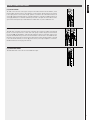
[15] LEVEL METER
This 12 LED elements level meter allows you to control the Main Mix output level. Keep the output level
below the “CLIP” indication to avoid overloaded signals that can cause distortion.
[16] COMPRESSORS
Input channels 1 to 6 are provided with intuitive and powerful single control dynamic compressors. With thresholds and ratio parameters properly
designed the F 16XR’s compressors allow even the most dynamically demanding signals to be controlled.
[17] EQ (MONO CHANNELS)
All the F 16XR’s mono channels and stereo channel 5/6 and 7/8 are provided with a sophisticated and precise 3-band EQ. Low frequency control sets in
at 100 Hz with a gain of +/-15 dB and shelving curve. Hi frequency control sets in at 10 kHz with a gain of +/-15 dB and shelving curve. Mid frequency
control provide a frequency selection between 100 Hz to 8 kHz with a gain of +/-15 dB and bell curve.
FRONT PANEL FUNCTIONS
ENGLISH

9
FRONT PANEL FUNCTIONS
[18] EQ (STEREO CHANNELS)
Stereo channels 9/10, 11/12, 13/14 and 15/16 are provided with precise 3-band EQ. Low frequency
control sets in at 100 Hz with a gain of +/-15 dB and shelving curve. Hi frequency control sets in at
10 kHz with a gain of +/-15 dB and shelving curve. Mid frequency control sets in at 1250 Hz with a
gain of +/-15 dB and bell curve.
[19] PRO DSP FX
F 16XR is equipped with an internal 16 preset FX board.
Rotating the encoder allows selection between 16 great sounding effects:
Select one of these effect presets to enrich your sound.
[20] PFL ACTIVE LED
This LED lights up when one or more PFL buttons are pressed.
[21] AUX1 - FX/AUX4
Each channel of the F 16XR mixer is provided with 4 auxiliary sends; the AUX1 and AUX2 are PRE fader send.
AUX3 is a POST or PRE fader send depending on the position of the AUX3 PRE/POST button ([25]). When the selection is pre-fader (button pressed) AUX3
takes the signal from the channel independently from the fader position; when the selection is post-fader (button unpressed) the AUX3 takes the signal
subjected to the fader position. FX/AUX4 send is always post fader.
FX/AUX4 send feed the internal PRO DSP FX board. The signal present in the FX/AUX4 send is also routed to the AUX4 OUTPUT jack present on the back
panel (see section [39] of this manual).
[22] FX TO AUX
This sends allow to routing the signal present in the FX return channel to AUX1, AUX2 and AUX3 sends.
[23] AUX1 TO FX/AUX4 MASTER KNOBS
These potentiometers control the master level of the auxiliary sends AUX1 to AUX FX/4. The PFL button,
when pressed, allows listening the signal present in the single aux out, through speakers connected to
the CTRL ROOM OUTPUT (see section [9] this manual) or through headphones connected to PHONES
OUTPUT (see section [7]).
[24] CTRL ROOM LEVEL KNOB
This is the level control of the signal routed to CTRL ROOM OUTPUT. During the mixer’s normal use the
MAIN MIX signal is routed to this output; when one or more PFL buttons are pressed the PFL bus signal
will be routed to CTRL ROOM OUTPUT and PHONES OUTPUT.
01. SMALL HALL
02. LARGE HALL
03. SMALL ROOM
04. BRIGHT ROOM
05. THIN PLATE
06. PLATE
07. SPRING REVERB
08. MULTITAP DELAY
09. ANALOG DELAY
10. CHORUS VERB
11. STEREO CHORUS
12. FLANGER
13. PHASER
14. GATED REVERB
15. FLANGER REVERB
16. VOCAL ECHO
ENGLISH

10
[25] AUX3 PRE/POST BUTTON
This button allows selection of the AUX3 position, pre-fader or post-fader. See section [21] of this
manual.
[26] PHONES LEVEL
This knob controls the level of the PHONES OUTPUT [7]. Set the PHONES LEVEL control to minimum
(-∞) before connect and wear headphones to avoid hearing loss.
[27] MONITOR SECTION
The MONITOR SECTION provides two “TO CTRL ROOM” buttons: the upper one select the audio path
to listen on speakers connected to CTRL ROOM OUTPUT; L/R audio path, when in upper position or
BUSSES audio path, when pressed. The lower one determines which pair of BUSSES to be listen: BUS
1/2 when in upper position or BUS 3/4 when pressed.
[28] PAN
These controls allow positioning of the signal present in the mono channel in the stereo image of the MAIN MIX.
[29] PAN/BAL
The control works as PAN when the channel is used in MONO configuration (XLR MIC INPUT) defining
the position of the signal into the stereo image of the stereo MAIN MIX. BAL (Balance) control allows
balancing of the position of the stereo channel (TRS jack line stereo input) into the stereo image of
the MAIN MIX.
[30] BAL
These controls characteristic of stereo channels allow balancing of the position of a stereo channel into
the stereo image of the MAIN MIX.
[31] MONO CHANNELS FADERS SECTION
This section allows the level of the MONO input channels from 1 to 8 to be controlled, and their routing to the output. Each one of the faders has several
control buttons. MUTE button when pressed inhibits the signal to flow to the output bus or main mix paths. The PFL button allows listening to the signal
present on the channel through speakers connected to the CTRL ROOM OUTPUT (see section [9] of this manual) or through headphones connected to
PHONES OUTPUT (see section [7]). MAIN and BUS 1/2 and BUS 3/4 buttons positioned on the right side of each fader allow the signal to be routed
respectively to MAIN MIX and/or STEREO BUS 1/2 and /or STEREO BUS 3/4.
[32] STEREO CHANNELS FADER SECTION
This section allows the level of the STEREO input channels from 9/10 to 15/16 to be controlled, and
their routing to the output. Each one of the faders has several control buttons. MUTE button when
pressed inhibits the signal to flow to the output bus or main mix paths. The PFL button allows listening
to the signal present on the channel through speakers connected to the CTRL ROOM OUTPUT (see
section [9] of this manual) or through headphones connected to PHONES OUTPUT (see section [7]).
MAIN and BUS 1/2 and BUS 3/4 buttons positioned on the right side of each fader allow the signal to
be routed respectively to MAIN MIX and/or STEREO BUS 1/2 and /or STEREO BUS 3/4.
FRONT PANEL FUNCTIONS
ENGLISH

11
[33] FX RET FADER
This fader controls the level of the signal coming from the internal PRO DSP FX. MUTE button, when
pressed, inhibits the signal to flow to the output bus or main mix paths. The PFL button allows listening
to the signal present on the channel through speakers connected to the CTRL ROOM OUTPUT (see
section [9] of the back panel description) or through headphones connected to PHONES OUTPUT (see
section [7]). MAIN, BUS 1/2 and BUS 3/4 buttons positioned on the right side of the fader allow the
signal to be routed respectively to MAIN MIX and/or STEREO BUS 1/2, and/or STEREO BUS 3/4.
[34] BUS 1/2, BUS 3/4 FADER
The faders BUS 1/2 and BUS 3/4 control the level of the stereo bus out. BUS 1/2 and BUS 3/4 can be fed
by each one of the input channels to create stereo audio groups routed to the physical BUS OUTPUTS
(see section [40]). The MUTE button, when pressed, inhibits the signal flow to the BUS output or main
mix paths. The MAIN button positioned close the BUS faders routes the BUS to the MAIN MIX. The
PFL button, when pressed, allows listening to the signal present into BUS through speakers connected
to the CTRL ROOM OUTPUT (see section [9] of this manual) or through headphones connected to
PHONES OUTPUT (see section [7] of this manual).
[35] MAIN MIX FADER
The MAIN MIX Fader controls the level of the MAIN MIX output.
FRONT PANEL FUNCTIONS
ENGLISH

12
[36] POWER SWITCH
Use this switch to turn on and off your F 16XR mixer.
[37] POWER SUPPLY INLET
Connect here the power cord provided. The internal power supply accepts power from 100 V to
240 V AC 50-60 Hz.
[38] USB TYPE B PORT
Use this to connect your computer for audio stereo recording of the MAIN MIX signal and audio
stereo playback. The computer connection does not require any driver and allows the recording and
reproduction of PCM audio at 44.1/48.0 kHz - 16 Bit. The audio signal coming from a computer
connected to the USB port could be reproduced through Channel 11/12 audio path (see section [14]
of this manual).
[39] AUX OUTPUTS
These TRS jack connectors provide +4 dB balanced audio output coming from auxiliary sends. Connect
your stage monitors or external effects input here.
[40] BUS OUTPUTS
These four balanced TRS jacks perform +4 dB audio out coming from BUSSES 1/2 and 3/4. The audio
levels of BUSSES 1/2 and 3/4 are controlled by the dedicated fader located on the front panel (see
section [34] of this manual).
REAR PANEL FUNCTIONS
ENGLISH
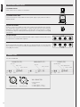
CONNECTORS
1/4” JACK CONNECTOR
Sleeve = Ground
Sleeve
Tip Ring
Tip = Hot
Ring = Cold
BALANCED (TRS)
Sleeve = Ground
SleeveTip
UNBALANCED (TS)
Tip = Hot
Tip
Sleeve = Ground
Ring = Right Channel
Tip=Left Channel
PHONES (TRS)
Ring Sleeve
XLR CONNECTOR
Connector pinout:
1 = earth
2 = audio signal (+ or “hot“)
3 = audio signal (– or “cold“)XLR Connector (F) XLR Connector (M)

13
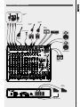
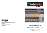
SUGGESTED CONFIGURATION
2 2 2 2 2 2 2 2 2 2
MAIN SPEAKERS
STUDIO
MONITORS
SYNTH
MICROPHONES
MICROPHONES
ELECTRIC
BASS
DRUM
MACHINE
ELECTRIC
GUITAR
ACOUSTIC
DRUM
STAGE
MONITOR
COMPUTER - DAW
ELECTRIC
GUITAR
ENGLISH

24
GAIN
48V SWITCH
+48V
PHANTOM POWER
LINE
MIC
2
3
1
HPF 80HZ
3 BAND EQ
10KHZ
MID-BAND FREQ. SEL. 100HZ-8KHZ
MID-BAND GAIN
100HZ
THRESHOLD
COMPRESSORS
PEAK
A U X 3_P R E
PAN
CHANNEL 1-8
GAIN
PHANTOM POWER
LINE
MIC
10KHZ
1.25KHZ
100HZ
PEAK
CHANNEL 9/10 - 11/12
AMP
3 BAND EQ
STEREO
LINE
AMP
LINE
10KHZ
100HZ
CHANNEL 13/14
3 BAND EQ
STEREO
LINE
1
2
1
2
GAIN
PEAK
LINE
10KHZ
100HZ
CHANNEL 15/16
2 BAND EQ
STEREO
LINE
1
2
1
2
GAIN
PEAK
1
3
5
2
4
6
MASTER
MAIN OUT L
MAIN OUT R
FX LEVEL
ENCODER
USB
METERS
CTRL ROOM - L
CTRL ROOM - R
CTRL ROOM LEVEL
HEADPHONES
PHONES LEVEL
LEVEL FADER
LEVEL FADERLEVEL FADER
MUTE
AUX1
AUX3 PRE
AUX3 POST
MAIN L
MAIN R
MAIN
A U X 3_P O S T
A U X 4
BUS 1
PFL R
A U X 4
2
3
1
MUTE
A U X 3_P R E
A U X 3_P O S T
AUX 1 OUTPUT
AUX 2 OUTPUT
PRE
POST
FX TO AUX1
AUX1 LEVEL
AUX2 LEVEL
2
3
1
2
3
1
DISPLAY
BUS1/2
BUS 1
BUS 2
1
3
5
2
4
6
1
3
5
2
4
6
FX
BUS1/2
BUS 2
2
3
1
PFL L
PFL
PFL
B A L
2
3
1
HPF 80HZ
USB AUDIO
INPUT
PFL
PFL
2
3
1
P R E / P O S T
2
3
1
MAIN
2
3
1
2
3
1
BUS1/2
2
3
1
2
3
1
PFL
2
3
1
FADER
PFL
MAIN
AUX1
AUX2
AUX2
AUX4
BUS 3
BUS 4
AUX1
AUX3 PRE
AUX3 POST
MAIN R
BUS 1
PFL R
BUS 2
PFL L
AUX2
AUX4
BUS 3
BUS 4
1
3
5
2
4
6
1
3
5
2
4
6
1
3
5
2
4
6
1
3
5
2
4
6
BUS3/4
H i - Z
C H A N N E L 6 O N LY
C H A N N E L 6 O N LY
A U X 1
A U X 2
MAIN
BUS1/2
1
3
5
2
4
6
1
3
5
2
4
6
1
3
5
2
4
6
BUS3/4
1.25KHZ
AUX4
2
3
1
MUTE
A U X 3_P R E
A U X 3_P O S T
2
3
1
PFL
B A L
1
3
5
2
4
6
AUX1
AUX2
MAIN
BUS1/2
1
3
5
2
4
6
1
3
5
2
4
6
1
3
5
2
4
6
BUS3/4
LEVELFADER
A U X 4
2
3
1
MUTE
A U X 3 P R E
A U X 3 POST
2
3
1
PFL
B A L
1
3
5
2
4
6
A U X 1
A U X 2
MAIN
BUS1/2
1
3
5
2
4
6
1
3
5
2
4
6
1
3
5
2
4
6
BUS3/4
AUX 3 OUTPUT
AUX3 LEVEL
2
3
1
PFL
AUX 4 OUTPUT
AUX4 LEVEL
2
3
1
PFL
FX TO AUX2
FX TO AUX3
2
3
1
BUS3/4
2
3
1
BUS 3
BUS 4
1
3
5
2
4
6
1
3
5
2
4
6
PFL
MAIN
FADERBUS 3/4 FADER
1
3
5
2
4
6
1
3
5
2
4
6
TO CTRL ROOM
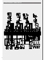
BLOCK DIAGRAM
E12 BLOCK DIAGRAM / SCHEMA A BLOCCHI

25
SPECIFICATIONS
Mono input Channels
Microphone inputs
Frequency response
Distortion (THD+N)
Sensitivity range
Max input
Mic input impedance
Phantom Power
Low cut
Line input
Frequency response
Distortion (THD+N)
Sensitivity range
Max input
Line input impedance
Stereo Input Channels
Line input
Frequency response
Distortion (THD+N)
Sensitivity range
Line input impedance
Mono Channels EQ
High
Mid
Low
Stereo Channels EQ
High
Mid
Low
DSP Section
DSP Processing
A/D and D/A converters
Type of effects
Footswitch
Outputs
Main Output
Max Main Mix Output Level
Aux Output
Max Aux Output Level
Stereo Bus 1/2 Output
Max Bus Output Level
Stereo Bus 3/4 Output
Max Bus Output Level
Ctrl Room
Phones Output
Power Supply
Internal Universal Power
Main Voltage
Power Consumption
Weight
Dimensions
RCF F 16XR
10 XLR Balanced
20 Hz - 20 kHz, +/- 1 dB
<0,003% at +0 dB, 20 Hz - 20 kHz
0 dB to -50 dB
+20 dBu
14 kΩ unbalanced
+48 V
80 Hz
8 TRS jack balanced
20 Hz – 20 kHz, +/- 1 dB
<0,003% at +0 dB, 20 Hz - 20 kHz
20 dB to -30 dB
+40 dBu
21 kΩ unbalanced
4 pairs TRS jack balanced and 2 pairs RCA unbalanced
20 Hz - 20 kHz, +/- 1 dB
<0,003% at +0 dB, 20 Hz - 20 kHz
20 dB to -30 dB
15 kΩ unbalanced
+/-15 dB @ 10 kHz Shelving
+/-15 dB @ Freq. sel. from 100Hz to 8kHz - Bell
+/-15 dB @ 100 Hz Shelving
+/-15 dB @ 10 kHz Shelving
+/-15 dB @ 1,250 kHz Bell
+/-15 dB @ 100 Hz Shelving
20/27 bit digital signal
24 bit
4 algorithms: reverb, chorus, delay, flanger - 16 presets
TS jack (for effect return mute and unmute)
1 pair of XLR male and 1 pair of TRS jacks
+28 dBu
4 TRS jacks
+28 dBu
2 TRS jacks
+28 dBu
4 TRS jacks
+28 dBu
1 pair of TRS jacks
1 Stereo jack
100 V - 240 V AC, 50 - 60 Hz
30 W
6,4 kg
L 480 mm, W 400 mm, H 100 mm
SPECIFICATIONS / SPECIFICHE

26
F 16XR REAR VIEW / VISTA POSTERIORE
F 16XR TOP VIEW / VISTA FRONTALE
2 2 2 2 2 2 2 2 2 2

27

www.rcf.it
RCF SpA: Via Raffaello, 13 - 42124 Reggio Emilia - Italy
tel. +39 0522 274411 - fax +39 0522 274484 - e-mail: rcfservice@rcf.it
10307625
-
 1
1
-
 2
2
-
 3
3
-
 4
4
-
 5
5
-
 6
6
-
 7
7
-
 8
8
-
 9
9
-
 10
10
-
 11
11
-
 12
12
-
 13
13
-
 14
14
-
 15
15
-
 16
16
-
 17
17
-
 18
18


RCF F 16XR Mixing Console Owner's manual
- Category
- Musical Equipment
- Type
- Owner's manual
Ask a question and I''ll find the answer in the document
Finding information in a document is now easier with AI
Related papers
Other documents
-
 Newhank AEROBIX XL Owner's manual
-
Harman Kardon GB4 User manual
-
 Soundcraft GB4 User manual
-
Alto TYPHOON SERIES User manual
-
-
ALLEN & HEATH ZED R16 Firewire User manual
-
Yamaha MG16XU User manual
-
-
 Audiodesign PAMX3.82 Owner's manual
-


