Page is loading ...

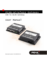
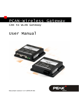
PCAN-Gateway
Quick Start Guide

© 2017-05 PEAK-System Technik GmbH - www.peak-system.com
Congratulations ...
... on your new PCAN-Gateway. This guide covers the basic configuration and
operation of the PCAN-Gateway product family.
Documentation
Detailed documentation in PDF format is available on the supplied product DVD
and on our website. See the last page of this quick start for download links.
Simplified EU Declaration of Conformity
PEAK-System Technik GmbH declares:
The product PCAN-Ethernet Gateway DR (IPEH-004010) is in compliance
with the EU EMC Directive 2014/30/EU.
The radio equipment PCAN-Wireless Gateway DR (IPEH-004011) and
PCAN-Wireless Gateway (IPEH-004020 and IPEH-004020-A) are in
compliance with the Directive 1999/5/EC.
The full texts of the EU declaration of conformity are available in the
documentation of each product. See the last page of this quick start for
download links.

© 2017-05 PEAK-System Technik GmbH - www.peak-system.com
Connectors
PCAN-Ethernet Gateway DR
(IPEH-004010)
CAN 1 & 2: High-speed CAN channels,
connectors via 4-pole screw-
terminal strips (Phoenix)
Power: Voltage supply (8 - 30 V)
LAN: RJ-45 connector
PCAN-Wireless Gateway DR
(IPEH-004011)
CAN 1 & 2: High-speed CAN channels,
connectors via 4-pole screw-
terminal strips (Phoenix)
Power: Voltage supply (8 - 30 V)
WLAN: 2.4 GHz dipole antenna
Pin Assignment CAN
1 CAN-High
2 CAN-Low
3 CAN-GND
4 CAN-Shield
1 2 3 4
Pin Assignment Power
1 GND
2 not connected
3 Vbat (8 - 30V)
4 Shield
1 2 3 4
CAN 1
CAN 2
Power
RS-232
Antenna
or RJ-45

© 2017-05 PEAK-System Technik GmbH - www.peak-system.com
PCAN-Wireless Gateway
(IPEH-004020)
CAN 1 & 2: High-speed CAN channels,
connectors via D-Sub, 9-pin
(in accordance with CiA® 303-1)
Power: Voltage supply (8 - 30 V)
WLAN: Internal chip antenna
PCAN-Wireless Gateway
(IPEH-004020-A)
CAN 1 & 2: High-speed CAN channels,
connectors via automotive
connector, 12-pin (Tyco)
Power: Voltage supply (8 - 30 V)
WLAN: Internal chip antenna
Pin Assignment D-Sub & Power
1 opt. +5V
2 CAN-Low
3 GND
4 Wake-up
6 GND
7 CAN-High
CAN 1 Power CAN 2
CAN 1, CAN 2, Power
1 Vb
2 GND
3, 9 CAN1-Low
4, 10 CAN1-High
5, 11 CAN2-Low
6, 12 CAN2-High
7 Wake-up
8 GND
Pin Assignment Tyco

© 2017-05 PEAK-System Technik GmbH - www.peak-system.com
Basic Configuration
Preparation
1 Power Supply: Connect the PCAN-Gateway to a suitable power supply
(8 - 30 V DC). When the Status LED is blinking green, the device is ready and
the default configuration is executed.
2 Computer: Configure your PC with IP address settings that correspond to
the default settings of the PCAN-Gateway (IP: 192.168.1.xxx, Subnet mask:
255.255.255.0).
3a IP Connection for the PCAN-Ethernet Gateway DR: Use the supplied RJ-45
network patch cord to connect the device to your LAN network.
3b IP Connection for the PCAN-Wireless Gateway (DR): Connect your PC to
the WLAN network that is provided by the PCAN-Gateway (SSID: PEAK
Wireless Default). The password can be found on the casing sticker.
4 Configuration Website: Open the device’s address: 192.168.1.10 in a web
browser to access the configuration website. Enter admin for username and
password and confirm with Enter. Now you can start with the basic device
configuration.

© 2017-05 PEAK-System Technik GmbH - www.peak-system.com
CAN Configuration
Open the page Network >> CAN to configure the CAN channels.
Bit Rate: Select a value from the drop-down menu. The
bit rate must match the one currently set on the
connected CAN bus.
Listen-Only-Mode: If the PCAN-Gateway should act as a pure
observer, not affecting the data traffic, Listen-
Only-Mode must be enabled.
Save your settings for each channel with the button Save Settings.

© 2017-05 PEAK-System Technik GmbH - www.peak-system.com
IP Configuration
Depending on your device the connection to the IP network is done via LAN or
WLAN. Open the page Network >> LAN or Network >> WLAN to configure the
IP interface.
Connection Settings: Only available on PCAN-Gateways with WLAN
interface! Enter the access data of the WLAN
network you will be connecting to.
Address Settings: Enter an IP address and Subnet mask that match
the settings of your IP network.
Please note: DHCP is not recommended.
After you have saved the settings, you are automatically logged out and the
basic configuration of the device is completed. For devices with WLAN interface:
After the basic configuration the default WLAN network is no longer available.
Please note: If the PCAN-Gateway is no longer accessible due to an incorrect
configuration for example, the device can be reset to factory defaults. To
perform this reset, press with a paper clip for more than 5 seconds into the
small reset hole.

© 2017-05 PEAK-System Technik GmbH - www.peak-system.com
Application Example
The PCAN-Gateways allow the connection of different CAN busses over IP
networks. CAN frames are wrapped in TCP or UDP message packets and then
forwarded via LAN or WLAN from one device to another.
CAN Bus A CAN Bus BIP NetworkGateway 1 Gateway 2
LAN
WLAN
In this application example, message traffic from CAN bus A is being forwarded
to CAN bus B via an IP network.
For this unidirectional data transmission two PCAN-Gateways and the creation
of a route on each device are required.

© 2017-05 PEAK-System Technik GmbH - www.peak-system.com
Gateway 1: Create a Send Route
Gateway 1 is connected to CAN bus A via its CAN channel 1. To transfer the CAN
messages to Gateway 2, you have to create a Send route on Gateway 1.
1 Add Route Open the configuration website of Gateway 1 and
go to the page Routing >> Manage Routes. Click the
button Add Route.
2 Configure Route Select Send: CAN > IP from the Choose the direction
drop-down list. Complete the form with the values
from the table below.
Status Activate
CAN CAN Channel 1 (connected to CAN bus A)
IP Address 192.168.1.202 (address of Gateway 2)
Port 50000
Protocol TCP
3 Confirm Click the Add Route button at the bottom of the page
to complete the route creation process. After saving,
the route will be displayed in the overview on the page
Routing >> Manage Routes.

© 2017-05 PEAK-System Technik GmbH - www.peak-system.com
Gateway 2: Create a Receive Route
Gateway 2 has to receive the messages sent by Gateway 1. Furthermore
the extracted CAN messages, have to be transferred to CAN bus B, which is
connected to CAN channel 2. To make that work, you have to create a Receive
route on Gateway 2.
1 Add Route Open the configuration website of Gateway 2 in
another browser tab and go to the page Routing >>
Manage Routes. Click the Add Route button.
2 Configure Route Select Receive: IP > CAN from the Choose the direction
drop-down list. Complete the form with the values
from the table below.
Status Activate
Port 50000 (like the Send route)
Protocol TCP (like the Send route)
CAN CAN Channel 2 (connected to CAN bus B)
3 Confirm Click the Add Route button at the bottom of the page
to complete the route creation process. After saving,
the route will be displayed in the overview on the page
Routing >> Manage Routes.

© 2017-05 PEAK-System Technik GmbH - www.peak-system.com
Final Check
Open the page Routing >> Manage Routes on both devices.
If the Status LEDs of the Send route on Gateway 1 and the
Receive route on Gateway 2 are green, everything is fine and the
unidirectional message forwarding is working.
Please note: If you like to setup a bidirectional message
transmission, you have to create a message forwarding in the
opposite direction. For this a Send route on Gateway 2 and a
Receive route on Gateway 1 are required.
A detailed description of this application example is available in
the documentation of your PCAN-Gateway.
Video Tutorials
With short video tutorials on YouTube, we demonstrate how to
configure and use the PCAN-Gateways.
www.youtube.com/user/peaksystemtechnik

© 2017-05 PEAK-System Technik GmbH - www.peak-system.com
Software Updates
Each model of the PCAN-Gateway product family requires its own software
update. Therefore, download the appropriate update package for your device
via the URLs below.
The update can be installed via the configuration website. Simply follow the
instructions on the page Device >> Software Update.
PCAN-Ethernet Gateway DR
Part No.: IPEH-004010
Software Package Download: www.peak-system.com/quick/DLP4010
Documentation (English): www.peak-system.com/quick/DOC4010E
PCAN-Wireless Gateway DR
Part No.: IPEH-004011
Software Package Download: www.peak-system.com/quick/DLP4011
Documentation (English): www.peak-system.com/quick/DOC4011E
Part No.: IPEH-004020 & IPEH-004020-A
Software Package Download: www.peak-system.com/quick/DLP4020
Documentation (English): www.peak-system.com/quick/DOC4020E
PCAN-Wireless Gateway
/