Page is loading ...

MICRImage
CHECK READER
COMMAND REFERENCE MANUAL
Manual Part Number: 99875175 Rev 7
OCTOBER 2008
REGISTERED TO ISO 9001:2000
Phone: (562) 546-6400
Technical Support: (651) 415-6800
www.magtek.com
1710 Apollo Court
Seal Beach, CA 90740
FAX: (562) 546-6301

ii
Copyright
©
2000-2009
MagTek
®
, Inc.
Printed in the United States of America
Information in this document is subject to change without notice. No part of this document may
be reproduced or transmitted in any form or by any means, electronic or mechanical, for any
purpose, without the express written permission of MagTek, Inc.
MagTek is a registered trademark of MagTek, Inc.
REVISIONS
Rev Number Date Notes
1 20 Oct 00 Initial Release
2 27 Jun 01 Front Matter: Removed UL statement from agency approvals.
Software License removed.
Section 1: Completely revised.
Section 2: Editorial changes, added commands SWI and PR12.
Section 3: Added commands SE, LE, DM, EM, BLK, UNBLK.
Section 4: Added commands: TI Cn, TI Fn, TI N[string], TI G[n],
TI T[#], TI Cn Fn N[string] T[#], TC and IS.
Section 5: Completely revised, now called Ethernet Interface.
Appendices A, B, C – no change.
Appendix D: Added Extended Error Codes
Removed Appendix for Downloading.
3 25 Apr 02 Sec 2: SWA Command – Host Port Parameters: RS-231 changed to
RS-232; Image Output Port: RS-233 changed to RS-232; Added
Doc Size Limits PR-30 –33.
Sec 4: Added BCn, Bar Code Commands.
Sec 5: Added PR13 – DNS 1 IP Address – PR19 – FTP File
Directory.
Appendix D: Deleted EEC 114; Added EEC 115, 116, 214, 232,
313, 595-598; Changed 310.
4 20 Dec 02 Sec 2: Added to note after Table 2-1; changed baud rate to 8
speeds; Table 2-4, Error and Status Codes, completely revised;
Added “or Modem” to note after Table 2-7; Clarified MICR Output
Port and File Transfer Protocol; Added SWF Command and Table 2-
8 and multi-scan notes; To SWF added extended status digits;
Added Suppress MICR and Multi-Scan paragraphs; Added DPI
values and note to Table 2-9 about TIFF spec; To PR34 added
amplitude qualifier; Added MICR Line Technical Options; Clarified
PR35; Sec 3: Clarified EM; Sec 4: Clarified TI, SF; added AI
Command; Sec 5: Changed Ethernet MICR Config to Ethernet or
Modem Network Config; Changed Ethernet Debug to Network
Debug; added Ethernet Only to PR0, PR1, PR2, PR3, PR4 PR5;
added Modem PPP Only to PR16, PR17, PR18.
5 03 Mar 03 Editorial. Sec 4: Modified AI. Sec 6: added examples PR34, 35.
Added PR36.
(Cont’d)

iii
REVISIONS (Cont’d)
6 12 May 03 Front Matter: Added ISO line to logo, added new Tech Support
phone number; Sec 2: Added Transfer Progress Messages, Sec 3:
Cmd DM, added scan information; Sec 5: Added Ethernet Debug
entries, added XU and XD Cmds.
7 21 Aug 03 Section 2: Added Enhanced Reading parameters to Table 2-8 and
description of Enhanced Reading in SWF Command.

iv
TABLE OF CONTENTS
SECTION 1. COMMANDS OVERVIEW......................................................................................................1
CONFIGURATION COMMANDS.............................................................................................................1
OPERATIONAL COMMANDS..................................................................................................................1
COMMAND LINE SYNTAX ......................................................................................................................2
INSTA-CHANGE CHECKS.......................................................................................................................2
MICRBASE SETUP PROGRAM FOR WINDOWS ..................................................................................2
SECTION 2. CONFIGURATION COMMANDS...........................................................................................5
SWITCH COMMANDS.............................................................................................................................5
SWA COMMAND – HOST PORT PARAMETERS...................................................................................5
Baud Rate.............................................................................................................................................6
Data, Stop Bits, and Parity...................................................................................................................6
CTS/DSR..............................................................................................................................................6
Inter-character Delay............................................................................................................................7
SWB COMMAND – MESSAGE FORMAT PARAMETERS .....................................................................7
Control Characters and MICR Data .....................................................................................................7
Communication Modes.........................................................................................................................8
Send Data After Error...........................................................................................................................8
Send Status After Data Parameter.......................................................................................................9
SWC COMMAND – MISCELLANEOUS FUNCTION PARAMETERS...................................................10
CMC-7 Character Set.........................................................................................................................10
Invalid Command Response..............................................................................................................10
Active RTS..........................................................................................................................................11
Data Header.......................................................................................................................................11
Card Data Message............................................................................................................................11
Extended Replies ...............................................................................................................................12
‘No MICR’ Response..........................................................................................................................12
SWD COMMAND – AUXILIARY PORT PARAMETERS .......................................................................12
Baud Rate...........................................................................................................................................13
Data, Stop Bits, and Parity.................................................................................................................13
CTS/DSR............................................................................................................................................13
Inter-character Delay..........................................................................................................................13
SWE COMMAND – DATA TRANSFER PARAMETERS .......................................................................14
MICR/MSR Output Port......................................................................................................................14
Image Output Port..............................................................................................................................14
File Transfer Protocol.........................................................................................................................14
SWF COMMAND – MICR OPTIONS.....................................................................................................15
Extended Status.................................................................................................................................15
Suppress MICR..................................................................................................................................16
Enhanced Reading.............................................................................................................................17
Transfer Progress Messages.............................................................................................................17

v
SWI COMMAND – IMAGE PARAMETERS ...........................................................................................18
Image Type.........................................................................................................................................18
HW COMMAND – HARDWARE PARAMETERS...................................................................................19
Disable/Enable Y Option ....................................................................................................................19
Disable/Enable Tracks .......................................................................................................................19
ID Card Decoding...............................................................................................................................19
EMF Detect.........................................................................................................................................20
FC – FORMAT CHANGE COMMAND...................................................................................................20
FILE NAMES...........................................................................................................................................20
DOCUMENT SIZE LIMITS .....................................................................................................................20
MICR LINE TECHNICAL OPTIONS.......................................................................................................20
SA – SAVE COMMAND .........................................................................................................................21
SECTION 3. GENERAL OPERATIONAL COMMANDS ...........................................................................23
VR – VERSION COMMAND...................................................................................................................23
SE – SERIAL NUMBER COMMAND......................................................................................................23
RS – RESET COMMAND.......................................................................................................................23
LE – LED COMMAND ............................................................................................................................23
DM – DISABLE MICRIMAGE COMMAND.............................................................................................24
EM – ENABLE MICRIMAGE COMMAND..............................................................................................25
BLK – BLOCK COMMAND.....................................................................................................................25
UNBLK – UNBLOCK COMMAND ..........................................................................................................25
SECTION 4. IMAGE SPECIFIC COMMANDS.........................................................................................27
TG – TIFF TAGS COMMAND ................................................................................................................28
TI – TRANSMIT IMAGE COMMAND .....................................................................................................28
FM – FILE MEMORY COMMAND..........................................................................................................29
SI – STORE IMAGE COMMAND ...........................................................................................................31
SF – SEND NEXT IMAGE FILE COMMAND.........................................................................................31
TC – SET FILE TIMER/FILE COUNTER COMMAND............................................................................32
IS – IMAGE STATUS COMMAND.........................................................................................................32
AI – APPEND IMAGE COMMAND.........................................................................................................33
SNIPPETS..............................................................................................................................................34
BCN – BAR CODE COMMAND .............................................................................................................35
SECTION 5. NETWORK INTERFACE......................................................................................................37
NETWORK IMAGE FTP.........................................................................................................................37
NETWORK TELNET COMMUNICATIONS............................................................................................37
ETHERNET OR MODEM NETWORK CONFIGURATION ....................................................................37
NETWORK CONFIGURATION PROPERTIES......................................................................................37
NETWORK DEBUG COMMANDS.........................................................................................................38
PING – Send ECHO Packet Command.............................................................................................38
ED – Ethernet Debug Command........................................................................................................38
XU – PPP Dial Up (Modem Only) Command.....................................................................................39

vi
XD – Modem Disconnect (Modem Only) Command..........................................................................39
DHCP SERVER CONFIGURATION.......................................................................................................39
SECTION 6. PROPERTY COMMANDS....................................................................................................41
PR0 – MICR IP Address Fixed Value (Ethernet Only).......................................................................41
PR1 – MICR IP Address Source (Ethernet Only)...............................................................................41
PR2 – MICR IP Subnet Mask Fixed Value (Ethernet Only)...............................................................41
PR3 – MICR Subnet Mask Source (Ethernet Only)...........................................................................41
PR4 – Gateway IP Address Fixed Value (Ethernet Only)..................................................................41
PR5 – Gateway IP Address Source (Ethernet Only)..........................................................................42
PR6 – FTP Name/IP Address Fixed Value ........................................................................................42
PR7 – FTP IP Address Source...........................................................................................................42
PR8 – FTP User ID Fixed Value ........................................................................................................42
PR9 – FTP User ID Source................................................................................................................42
PR10 – FTP Password Fixed Value...................................................................................................42
PR11 – FTP Password Source ..........................................................................................................42
PR12 – File Name Specification.........................................................................................................43
PR13 – DNS 1 IP Address (Ethernet Only)........................................................................................43
PR14 – DNS 2 IP Address (Ethernet Only)........................................................................................43
PR15 – DNS IP Address Source (Ethernet Only)..............................................................................43
PR16 – Phone (Modem PPP Only)....................................................................................................44
PR17 – User ID (Modem PPP Only)..................................................................................................44
PR18 – User Password (Modem PPP Only)......................................................................................44
PR19 – FTP File Directory ...............................................................................................................44
PR20 through PR29 – Predefined Snippets.......................................................................................44
PR30 – Minimum Length....................................................................................................................45
PR31 – Minimum Height ....................................................................................................................45
PR32 – Maximum Length...................................................................................................................45
PR33 – Maximum Height ...................................................................................................................45
PR34 – MICR Threshold....................................................................................................................45
PR35 – MICR Amplitude Scale..........................................................................................................46
PR36 – Modem Initialization (Modem PPP Only) ..............................................................................46
APPENDIX A. FORMAT LIST...................................................................................................................47
APPENDIX B. CHECK READING.............................................................................................................65
E13-B CHARACTER SET ......................................................................................................................65
CMC-7 CHARACTER SET.....................................................................................................................65
CHECK LAYOUTS .................................................................................................................................66
MICR FIELDS.........................................................................................................................................67
1-Transit Field.....................................................................................................................................67
2-On-Us Field.....................................................................................................................................67
3-Amount Field...................................................................................................................................68
4-Auxiliary On-Us Field ......................................................................................................................68

vii
APPENDIX C. ASCII CODES....................................................................................................................69
APPENDIX D. EXTENDED ERROR CODES............................................................................................71
INDEX .........................................................................................................................................................75
TABLES
Table 2-1. SWA Command – Host Port Parameters---------------------------------------------------------------------6
Table 2-2. SWB Command – Message Format---------------------------------------------------------------------------7
Table 2-3. Control Characters-------------------------------------------------------------------------------------------------8
Table 2-4. Error and Status Codes-------------------------------------------------------------------------------------------8
Table 2-5. SWC Command – Miscellaneous Parameters------------------------------------------------------------10
Table 2-6. SWD Command – Auxiliary Port Parameters -------------------------------------------------------------12
Table 2-7. SWE Command – Data Transfer Options------------------------------------------------------------------14
Table 2-8. SWF Command – MICR Options-----------------------------------------------------------------------------15
Table 2-9. SWI Command – Image Parameters------------------------------------------------------------------------18
Table 2-10. HW Command---------------------------------------------------------------------------------------------------19
Table 3-1. LED Control--------------------------------------------------------------------------------------------------------24
Table B-1. CMC-7 Nonnumeric Characters------------------------------------------------------------------------------66
FIGURES
Figure 1-1. MICRImage Check Reader -----------------------------------------------------------------------------------viii
Figure B-1. Personal Checks ------------------------------------------------------------------------------------------------66
Figure B-2. Business Checks------------------------------------------------------------------------------------------------67

viii
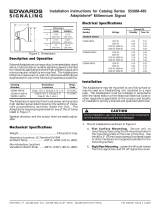
Figure 1-1. MICRImage Check Reader

1
SECTION 1. COMMANDS OVERVIEW
This manual describes the use of all the commands and programmable options available for the
MICRImage Reader. The MICRImage commands can be classified into two general groups:
Configuration Commands and Operational Commands.
CONFIGURATION COMMANDS
As the name implies, these commands are used to configure the MICRImage Reader. These
commands can also be accessed using Insta-change checks and the MICRbase Setup Program for
Windows (see below). Additionally, all the parameters and options controlled by the
configuration commands can be factory set as specified by the user when ordering.
The current list of configuration commands follows for the standard unit (see Section 2 for a
complete description of these commands):
• SWA – Switch A command
• SWB – Switch B command
• SWC – Switch C command
• SWD – Switch D command
• SWE – Switch E command
• SWF – Switch F command
• HW – Hardware command
• FC – Format Change command
• SA – Save Configuration command
• PR12 – Filename Configuration
• PR20 – PR29 - Snippets
• PR30 – PR33 - Doc Size Limits
• PR34 – PR35 – MICR Line Technical
Options
The current list of configuration commands follows for the Ethernet and Modem Options (see
Section 5 for a complete description of these commands):
• PR0 – MICR IP Address Fixed Value
• PR1 – MICR IP Address Source
• PR2 – MICR IP Subnet Mask Fixed
Value
• PR3 – MICR Subnet Mask Source
• PR4 – Gateway IP Address Fixed Value
• PR5 – Gateway IP Address Source
• PR6 – FTP IP Address Fixed Value
• PR7 – FTP IP Address Source
• PR8 – FTP User ID Fixed Value
• PR9 – FTP User ID Source
• PR10 – FTP Password Fixed Value
• PR11 – FTP Password Source
• PR13 – DNS1 IP Address
• PR14 – DNS2 IP Address
• PR15 – DMS IP Address Source
• PR16 – Phone #
• PR17 – User ID
• PR18 – User Password
• PR19 – FTP File Directory
OPERATIONAL COMMANDS
Operational commands provide access to additional parameters and options that control the
operation of the MICRImage reader.
The current list of general operational commands follows (see Section 3 for a complete
description of these commands):
• VR – Version command
• RS – Reset command
• LE – LED command
• DM – Disable MICR command
• EM – Enable MICR command
• BLK – Block Command
• UNBLK – Unblock Command

MICRImage Check Reader
2
The following are operational commands that are image specific (see Section 4 for a complete
description of these commands):
• TG – TIFF tag command
• TI – Transmit Image command
• FM – File Memory command
• SI – Store Image command
• SF – Send next image File command
• TC – Set file and timer counter
command
• IS – Image Status command
• AI – Append Image command
• BC – Bar Code command
COMMAND LINE SYNTAX
Unless otherwise noted, commands are “free form” in that spaces may be inserted between
parameters, numbers, and file names (but not between digits). These spaces are ignored. Spaces
within a string are retained.
Lower case letters are converted to upper case letters except in strings. Strings must end with ‘]’
or <CR>. If ‘\’ is used in a string, the character that follows it replaces the ‘\’. For example, if
the command line has the string: Hello[World\] and \\us\\], the resulting string will be:
Hello [World] and \us\.
All commands must end with <CR>.
INSTA-CHANGE CHECKS
The Insta-Change check is a MICR encoded document that contains commands and options used
to set configuration parameters in the MICRImage Reader. Multiple commands and options may
be contained on one Insta-Change check. Also, multiple Insta-Change checks may be required to
configure some of the parameters.
When used, the Insta-Change checks are run through the MICR Reader the same as a standard
check, and the options to be used are automatically configured. When the Insta-Change check is
run through the MICR Reader and read successfully, the LED indicator will blink green. If the
LED indicator turns red, the read is not successful. Try again or use a different Insta-Change
check. To obtain Insta-Change checks, notify a MagTek representative and specify what option
will be used.
MICRBASE SETUP PROGRAM FOR WINDOWS
The MICRbase setup program (P/N 22000021) allows the user to control all the programmable
options available in the MICRImage Reader.

Section 1. Commands Overview
3
The program provides a graphical, user-friendly interface that hides the complexities involved in
manually entering MICRImage commands. The user is no longer required to know the specific
commands or the detail data associated with each command. However, the program still allows
manual entry of commands for advanced users. For more detailed information, refer to the
MICRbase Setup Program Reference Manual (P/N 99875102).
The MICRbase setup program may also be downloaded from the Internet at www.magtek.com
under Software/Demo Programs.

MICRImage Check Reader
4

5
SECTION 2. CONFIGURATION COMMANDS
Configuration commands are used to setup configuration parameters in the MICRImage Reader.
A complete description of these commands follows:
SWITCH COMMANDS
These commands control internal “software” switches used to configure the MICRImage reader.
The switch commands include SWA, SWB, SWC, SWD, SWE, SWF, SWI, HW, FC, PR12, and
SA commands.
When sending configuration data for a software switch, 8 ASCII bits must always be provided
(“0”= hex 30, and “1”=hex 31). The MICRImage will execute the command but it will not reply.
For example, to execute the SWA command with configuration data, send the command as
follows:
SWA 01010101<CR>
To make a switch command permanent, follow the switch command with the SA command
(Save command) as follows:
SWA 01010101<CR>
SA <CR>
If a switch command is sent without configuration data, MICRImage will reply with the current
settings for that switch.
SWA COMMAND – HOST PORT PARAMETERS
This command controls the communication parameters for the RS-232 Host port. The
parameters for this command are listed in Table 2-1.
Note
The MICRImage includes an RS-232 auxiliary port that can be
configured in a similar manner using the SWD command.

MICRImage Check Reader
6
Table 2-1. SWA Command – Host Port Parameters
BITS FUNCTION
7 6 5 4 3 2 1 0
0 0 0 Baud Rate: 57600
0 0 1 Baud Rate: 38400
0 1 0 Baud Rate: 115200
0 1 1 Baud Rate: 1200
1 0 0 Baud Rate 2400
1 0 1 Baud Rate: 4800
1 1 0 Baud Rate: 9600
1 1 1 Baud Rate: 19200
0 0 0 Data, Stop Bits, Parity: 8, 1, None
1 0 0 Data, Stop Bits, Parity: 8, 2, None
0 0 1 Data, Stop Bits, Parity: 8, 1, Even
1 0 1 Data, Stop Bits, Parity: 8, 1, Odd
0 1 0 Data, Stop Bits, Parity: 7, 1, Even
1 1 0 Data, Stop Bits, Parity: 7, 2, Even
0 1 1 Data, Stop Bits, Parity: 7, 1, Odd
1 1 1 Data, Stop Bits, Parity: 7, 2, Odd
0 CTS/DSR: Use
1 CTS/DSR: Ignore
0 Intercharacter Delay: No
1 Intercharacter Delay: Yes
Note
The new settings for the serial port will not become effective unless
SWA has been saved and until the RS command is executed.
Baud Rate
The Baud Rate is one of eight speeds at which the MICRImage communicates with the host.
The lowest speed is 1200 baud, and the highest is 115200.
Data, Stop Bits, and Parity
Data refers to the number of data bits used to transmit every character; the options available are 7
or 8. Stop Bits refer to the number of bits used to indicate the end of transmission for every
character; the options available are 1 or 2. Parity refers to a means of detecting bit-level
transmission errors for every character; the options available are None, Even or Odd.
CTS/DSR
When CTS/DSR (Clear to Send/Data Set Ready) is set to Ignore, the MICRImage sends data to
the host without waiting for the CTS and DSR signals to be active. When CTS/DTS is set to
Use, the MICRImage waits for the CTS and DSR signals to be active before sending data.

Section 2. Configuration Commands
7
Inter-character Delay
The inter-character delay is used to increase the time between characters transmitted from the
MICRImage. The delay between characters is 13 ms for baud rates of less than 9600 and
approximately 1ms for baud rates of 9600 and higher.
SWB COMMAND – MESSAGE FORMAT PARAMETERS
The SWB command controls the message format, shown in Table 2-2.
Table 2-2. SWB Command – Message Format
BIT FUNCTION
7 6 5 4 3 2 1 0
0 0 <LF>: No
0 1 <LF>: Yes
0 0 <CR>: No
0 1 <CR>: Yes
0 0 <ETX>: No
0 1 <ETX>: Yes
0 0 <ESC>: No
0 1 <ESC>: Yes
0 0 <STX>: No
0 1 <STX>: Yes
0 Send Data After Error?: No
1 Send Data After Error?: Yes
0 Send Status After Data?: No
1 Send Status After Data?: Yes
0 0 0 0 0 0 Comm Mode: 0 - Data Only
1 0 0 0 0 0 Comm Mode: 1 - Data <CR>
0 0 0 0 0 1 Comm Mode: 2 - Data -<LF>
0 0 0 0 1 1 Comm Mode: 3 - Data -<CR><LF>
0 0 1 0 0 0 Comm Mode: 4 - <ESC> Data
0 0 1 0 1 0 Comm Mode: 5 - <ESC> Data<CR>
0 1 0 1 0 0 Comm Mode: 6 - <STX> Data<ETX>
1 0 0 0 0 1 Comm Mode: 7 - Packet Mode
(<STX>Data<ETX><LRC>)
Control Characters and MICR Data
Control Characters may be added to the MICR data message. The characters are always in the
following locations:
<STX> <ESC> data <ETX> <CR> <LF>
The control characters, descriptions, and hex values are shown in Table 2-3.

MICRImage Check Reader
8
Table 2-3. Control Characters
CONTROL
CHARACTER
DESCRIPTION
HEX VALUE
<STX> Start of Text 02
<ESC> Escape 1B
<ETX> End of Text 03
<CR> Carriage Return 0D
<LF> Line Feed 0A
For example, if <STX> and <CR> are set to YES, the message from the MICRImage will look
like this:
<STX>data<CR>
Communication Modes
The selection of Comm Modes is a quick way of selecting multiple Control Characters. For
instance, to send a carriage return/line feed pair after the data, you can specify Comm Mode 3.
Comm Mode 7, also known as Packet Mode, calculates an LRC (Longitudinal Redundancy
Check), and appends it to the data message. Also, if a <NAK> (hex 15) character is received in
this mode, the MICRImage will resend the last message.
Send Data After Error
The parameter Send Data After Error specifies whether the MICRImage will return data to the
host after a read error. If YES is selected and the MICRImage reads a check with an error, the
MICRImage will send the data back to the host. If NO is selected and the MICRImage finds an
error, it will discard the data and nothing will be sent. The error conditions are listed in
Table 2-4.
Table 2-4. Error and Status Codes
PRIORITY CODE TYPE DESCRIPTION
10 01 Error No MICR data: no transit and no account found
9 09 Status Mexican check
8 08 Status Canadian check
7 05 Error No transit, bad character, bad length, bad check digit
6 07 Error No account, bad character
5 04 Error Bad character in check number
5 04 Status No check number
4 12 Status Short Account (maybe caused by mis-parsed check#)
3 03 Status Low MICR signal, good read
2 10 Status Business check
1 11 Status Amount field present
0 00 Status No error, check OK

Section 2. Configuration Commands
9
Notes:
• The LED indicator will turn red on all error conditions.
• The absence of a check number is not considered an error.
• If a multiple error occurs, the error or status code with the highest priority is reported.
• All unreadable MICR characters are transmitted as an “?” ASCII character (hex 3F), except
for Format 00xx (See Section 5).
Send Status After Data Parameter
The Send Status After Data Parameter makes the MICRImage append a two-digit error/status
code to the end of the MICR data. For most formats (See Appendix A) the error/status code will
always be preceded by a forward slash (/). The error/status codes are listed in Table 2-4.
For example, if a Canadian check (code 08) is read and had no errors, and the MICR data is
“1234567890”, then the message from the MICRImage will look like this:
1234567890/08
The status code is always at the end of the data, not the end of the message. For example, using
the above conditions, with the message format set to send <STX> and <ETX>, the message from
the MICRImage will look like this:
<STX>1234567890/08<ETX>

MICRImage Check Reader
10
SWC COMMAND – MISCELLANEOUS FUNCTION PARAMETERS
The SWC command controls miscellaneous parameters, shown in Table 2-5 and described
below.
Table 2-5. SWC Command – Miscellaneous Parameters
BITS FUNCTION
7 6 5 4 3 2 1 0
0 CMC-7 Character Set: No
1 CMC-7 Character Set: Yes
0 0 Invalid Commands: ?<CR>
0 1 Invalid Commands : No Reply (Header
Required)*
1 0 Invalid Commands: No Reply (no header
required)
1 1 Ignore all Commands
0 Active RTS: No
1 Active RTS: Yes
0 Data Header: No
1 Data Header: Yes
0 Card Data Message: Multiple
1 Card Data Message: Single
0 Compatible Replies
1 Extended Replies**
0 Send only if MICR (Compatible)
1 ‘No MICR’ Response**
*Header Required means all commands must be preceded by a GS character (Hex 1D).
**Setting these bits means the Reader may not be compatible with applications using previous
MagTek MICR Products.
CMC-7 Character Set
If NO is selected, the MICR Reader will only read E13-B characters. When YES is selected, the
MICR Reader will read both CMC-7 and E13-B characters (see Appendix B). However, the
MICR Reader will only output raw data ("as is" on the check) for checks with CMC-7 characters.
Invalid Command Response
Invalid command response is the action the MICRImage takes upon receipt of a command it
does not recognize. It can also be used to stop the MICRImage from receiving any more
commands.
The first option “?<CR>” is the default. If the MICRImage receives an unrecognized
command, it will return a question mark and carriage return to the host. The MICRImage will
then return to an idle state and wait for further commands or check/credit card reads.
For the second option, “no reply - header required,” the MICRImage will only execute
commands preceded by a GS ASCII character (hex 1D), and it will not reply to invalid

Section 2. Configuration Commands
11
commands. When this option is selected, all messages received without a GS header will be
transmitted “as received” through the RS-232 auxiliary port.
For the third option, “no reply,” the MICRImage will execute all valid commands, but it will not
reply to invalid commands.
The fourth option, “ignore all commands,” causes the MICRImage to stop receiving any Host
data and to ignore any further commands. Even the SA (Save) command is ignored and
therefore this fourth option is only temporary. To make this option permanent or to reset it, you
must use an Insta-Change check.
Active RTS
When this function is set to YES, the MICRImage will raise RTS and wait 5 seconds for CTS to
become active before sending any data. If the 5 seconds expire and CTS is not active, the data
message will be discarded and nothing will be sent.
Data Header
If YES is selected, a single character header precedes the data. For MICR data, the message is
transmitted as follows:
‘C’[data]
For card data, the header position on the message is controlled by the Card Data Message
parameter (see below). Therefore, the message may be transmitted as follows:
If Multiple Message: ‘M’[TK1]‘M’[TK2]’M’[TK3]
If Single Message: ‘M’[TK1] [TK2] [TK3]
It is important to note that the Data Header precedes the data and not the message. For example,
if <STX>, <ETX> and Data Header are set to YES, a MICR data message will be transmitted as
follows:
<STX>‘C’[data]<ETX>
Card Data Message
This parameter determines the structure of the output message for the individual tracks when a
credit card is read. If Multiple is selected, the Control Characters (see SWB, below) and Data
Header (see Data Header, above) are added to each track individually. On the other hand, if
Single is selected, all available tracks are lumped together into a single message. For example, if
<STX>, <ETX> and Data Header are set to YES, the output message may be transmitted as
follows:

MICRImage Check Reader
12
If Multiple Message: <STX>‘M’[TK1]<ETX><STX>‘M’[TK2]<ETX><STX>‘M’[TK3]<ETX>
If Single Message: <STX>‘M’[TK1] [TK2] [TK3]<ETX>
Extended Replies
There are a number of commands in the standard MICR command set that do not provide any
response when the operation is completed or with a simple '?<CR> when an error occurs. By
setting this option, commands that normally provide no response will return 'OK<CR>' if the
command executes successfully. For commands that respond with a '?<CR>' to report an error,
the extended reply is '?xxx<CR>' where xxx is a three-digit error code. See Appendix D for a
complete listing of the error codes.
‘No MICR’ Response
For applications where both MICR and non-MICR encoded documents will be scanned, setting
this option will provide a 'No MICR' response when no MICR characters are detected.
SWD COMMAND – AUXILIARY PORT PARAMETERS
The SWD command, shown in Table 2-6, controls the communication parameters for the RS-232
Auxiliary Port.
Table 2-6. SWD Command – Auxiliary Port Parameters
BITS FUNCTION
7 6 5 4 3 2 1 0
0 0 0 Baud Rate: 57600
0 0 1 Baud Rate: 38400
0 1 0 Baud Rate: 115200
0 1 1 Baud Rate: 1200
1 0 0 Baud Rate 2400
1 0 1 Baud Rate: 4800
1 1 0 Baud Rate: 9600
1 1 1 Baud Rate: 19200
0 0 0 Data, Stop Bits, Parity: 8, 1, None
1 0 0 Data, Stop Bits, Parity: 8, 2, None
0 0 1 Data, Stop Bits, Parity: 8, 1, Even
1 0 1 Data, Stop Bits, Parity: 8, 1, Odd
0 1 0 Data, Stop Bits, Parity: 7, 1, Even
1 1 0 Data, Stop Bits, Parity: 7, 2, Even
0 1 1 Data, Stop Bits, Parity: 7, 1, Odd
1 1 1 Data, Stop Bits, Parity: 7, 2, Odd
0 CTS/DSR: Use
1 CTS/DSR: Ignore
0 Intercharacter Delay: No
1 Intercharacter Delay: Yes
/