Toro 60in E-Z Vac Blower and Drive Kit, 2016 and After Grandstand Mower Installation guide
- Type
- Installation guide
This manual is also suitable for
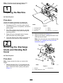
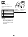
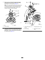
Toro 60in E-Z Vac Blower and Drive Kit, 2016 and After Grandstand Mower is a device that can be used to attach a blower and finishing kit to a Toro Grandstand mower. The kit includes a blower mount, pulley and idler assemblies, a belt, and a belt cover. The blower and finishing kit can be used to collect grass clippings and other debris from the lawn. The kit is easy to install and comes with all the necessary hardware. With this kit, you can easily convert your Toro Grandstand mower into a powerful and efficient lawn care machine.
Toro 60in E-Z Vac Blower and Drive Kit, 2016 and After Grandstand Mower is a device that can be used to attach a blower and finishing kit to a Toro Grandstand mower. The kit includes a blower mount, pulley and idler assemblies, a belt, and a belt cover. The blower and finishing kit can be used to collect grass clippings and other debris from the lawn. The kit is easy to install and comes with all the necessary hardware. With this kit, you can easily convert your Toro Grandstand mower into a powerful and efficient lawn care machine.


-
 1
1
-
 2
2
-
 3
3
-
 4
4
-
 5
5
-
 6
6
-
 7
7
-
 8
8


Toro 60in E-Z Vac Blower and Drive Kit, 2016 and After Grandstand Mower Installation guide
- Type
- Installation guide
- This manual is also suitable for
Toro 60in E-Z Vac Blower and Drive Kit, 2016 and After Grandstand Mower is a device that can be used to attach a blower and finishing kit to a Toro Grandstand mower. The kit includes a blower mount, pulley and idler assemblies, a belt, and a belt cover. The blower and finishing kit can be used to collect grass clippings and other debris from the lawn. The kit is easy to install and comes with all the necessary hardware. With this kit, you can easily convert your Toro Grandstand mower into a powerful and efficient lawn care machine.
Ask a question and I''ll find the answer in the document
Finding information in a document is now easier with AI
Related papers
-
Toro Blower and Drive Kit, Z Master Professional 7500-D Series Riding Mower With 60in TURBO FORCE Side Discharge Mower Installation guide
-
-
-
Toro 48in Blower and Drive Kit, Grandstand Mower Installation guide
-
-
-
-
-
-
Toro Blower and Drive Kit, 60in E-Z Vac for Z Master Mower Installation guide
Other documents
-
Ariens 81504500 User manual
-
Ariens 81504500 User manual
-
 Exmark 135-2604 User manual
-
 Exmark Ultra Vac QDS Laser Z User manual
-
 Exmark 000 & Higher User manual
-
 Exmark ULTRA VAC UVD60 User manual
-
Exmark LAZER Z User manual
-
Exmark ultra vac LAZER Z XP User manual
-
 Exmark Ultra Vac QDS Frontrunner FRCK724 User manual
-
 Exmark LAZER Z HP User manual


