Page is loading ...

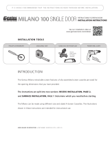
The instructions are split into two sections: RECESS INSTALLATION, PAGE 2, and
SURFACE INSTALLATION, PAGE 6. Determine which you need before starting.
INSTALLATION TOOLS
SCREENED PORCH • GAZEBOS • GARAGE OPENINGS
INSTALLATION INSTRUCTIONS
GrandVue E800
IT IS HIGHLY RECOMMENDED THAT THE INSTRUCTIONS BE READ THROUGH BEFORE INSTALLATION.
LARSON GRANDVUE E800 INSTRUCTIONS • PART NUMBER : 202220701-0219
PHILLIPS SCREWDRIVER
MEASURING TAPE
HAND-HELD OR POWER SAW
POWER DRILL & BITS RUBBER MALLET
Use saw
blade suitable
for cutting
aluminum.
NEEDLE PLIERS
PENCIL OR PEN

PAGE 2
J
D
F
L
L
K
O
O
A
B
B
F
J
J
B
H
E
E
M
I
I
C
C
N
N
N
N
N
N
N
N
G
A Screen Cassette Assembly
B Inside Rails
C Outside Rails
D Pull Bar
E Pull Bar End Caps
F End Cap with Spring
G End Cap with Operating Wand
H Chain Lock
I Recess Mount Clips
J Weatherstrip
K Foot Release Lever
L Pull Bar Locks
M Weight Bar
N #8 x 1” (25mm) Panhead Screw
O #6 x 3/8” (9mm) Phillips
Panhead Screw
PART DESIGNATIONS
GrandVue E800

Record your opening measurements on the chart below to calculate your
measurements.
Cut all parts to length using the calculations above.
Keep the plastic film on the cassette until all cuts are completed.
MEASURING AND CUTTING
Determine the maximum opening height & width for mounting your
screen, as shown below. Check for interference with any door or window.
1
Width
GRANDVUE 800 INSTALLATION INSTRUCTIONS
PAGE 3
RECESS INSTALLATION
JAMB JAMB
OPENING WIDTH
TOP VIEW
SIDE VIEW
HEAD
INSIDE
OUTSIDE
OUTSIDE
INSIDE
I-RECESS MOUNT CLIP
OPENING HEIGHT
SILL or FLOOR
IMPORTANT
Be sure to make
smooth, straight cuts. Only
cut the A-Screen Cassette
Assembly on the end
without the G-End Cap with
Operating Wand.
Height
OPENING WIDTH
"
LESS 7/8" TO ALLOW
FOR END CAPS
CASSETTE LENGTH (A)
= "
OPENING HEIGHT
"
LESS 2-1/8" TO ALLOW
FOR CASSETTE END CAPS
AND RECESS MOUNT CLIPS
INSIDE & OUTSIDE RAIL
LENGTHS (B & C)
= "
– 7/8"
– 2
1
/
8
"

PAGE 4
PREPARING THE SCREEN CASSETTE
Insert F-End Cap with Spring into the correct end of the A-Screen Cassette
Assembly [Fig 2A] (the assembly will only fit correctly in one end). Make sure to
line up the spring and bushing notches with one of the small slots in the center
screen tube. Wind the spring clockwise the number of turns designated in the fol-
lowing chart and push the F-End Cap with Spring in place on the A-Screen Cas-
sette Assembly. A rubber mallet is helpful to fully seat the F-End Cap with Spring.
Note that the spring in the cassette is for tension only. You will need to raise and
lower the screen by using the G-End Cap with Operating Wand.
2
3
SIDE VIEW
HEAD
OUTSIDE
INSIDE
I-Recess Mount Clip
OPENING WIDTH
36”- 72”
73”-120”
120”-140”
140”-192”
SPRING TENSION
25
30
35
40
OPPOSITE END OF CARTRIDGE
Test Operating Wand (see page 10) for smooth operation. If it’s too tight, loosen
allen screw on the G-End Cap with Operating Wand. Insert the G-End Cap with
Operating Wand into A-Screen Cassette Assembly and push into place.
Slide one piece of the J-Weatherstrip into bottom slot of D-Pull Bar and the
other piece into the top of A-Screen Cassette Assembly. The M-Weight Bars are
already inserted inside the D-Pull Bar. Now insert the E-Pull Bar End Caps into
ends of D-Pull Bar [Fig 2B].
MOUNTING THE SCREEN CASSETTE
Mount the I-Recess Mount Clips to the inside of opening. When installed, the clips
should be centered above the cassette. Install a N-#8x1” (25mm) Panhead Screw
into the center of the slot to allow front to back adjustment [Fig 3].
Snap the A-Screen Cassette Assembly into place. Secure the A-Screen Cassette
Assembly in place by screwing the F-End Cap and G-End Cap to the side jamb of
the opening. The I-Recess Mount Clips and A-Screen Cassette Assembly may be
reversed to face toward the inside or outside of an opening depending upon which
side the Operating Wand needs to be accessible.
NOTE: the I-Recess Mount Clips lower the A-Screen Cassette Assembly in the
opening by 1/4”. The same 1/4” gap should be left above the F & G-End Caps to
avoid bowing the cassette.
D
A
J
J
E
E
M
F
A
2A
2B
3
GRANDVUE 800 INSTALLATION INSTRUCTIONS
RECESS INSTALLATION

PAGE 5
CHAIN LOCK
Position H-Chain Lock on the side wall jamb near the A-Screen Cassette
Assembly where it can engage the operating wand chain. Attach to the jamb
using a N-#8 x 1" (25mm) Phillips Panhead Screw.
When the screen is fully extended and being used, the Operating Wand should be
operated so that the screen fabric is taut in the opening. If necessary, the exposed
chain can be secured by the H-Chain Lock to help retain the screen fabric in the
B-Inside Rails as wind blows against the screen fabric.
5
FOOT RELEASE LEVER
The K-Foot Release Lever is an optional feature that makes it easier
to slightly rotate the D-Pull Bar in order to disengage the L-Pull Bar
Locks [Fig 4C] without bending over. Before installing, position the
K-Foot Release Lever 12" to 20" from the end of the D-Pull Bar on
the side closest to the Operating Wand. Attach the K-Foot Release
Lever to the D-Pull Bar using two O-#6 x 3/8” (9mm) Phillips
Panhead Screws.
6
LEFT
RIGHT
B
L
C
B
L
C
D
K
O
B
E
4A
4B
4C
6
Windy conditions may affect the performance of a retractable screen. Retract the
screen in windy circumstances, during inclement weather, when not needed to
support immediate ventilation or during prolong periods when not used.
INSTALLING SIDE RAILS
Install the L-Pull Bar Locks at the bottom of each B-Inside Rail. Be sure that
the L-Pull Bar Locks can engage the D-Pull Bar as shown [Fig 4C]. Slide both
C-Outside Rails onto the tabs protruding from the F and G-Cassette End Caps
[Fig 4A]. Attach to jamb with N-#8x1” (25mm) Panhead Screws. Press B-Inside
Rails into C-Outside Rails [Fig 4B] with the shorter pile to the inside [Fig 4D]
until they are evenly seated.
Using the height adjustment wheels on the L-Pull Bar Locks, adjust the height
to the appropriate level so they easily engage the D-Pull Bar. When correctly
adjusted, the latching and unlatching should be smooth and easy.
4
Shorter Pile
4D
See page 10 for Operating Wand Instructions.
GRANDVUE 800 INSTALLATION INSTRUCTIONS
RECESS INSTALLATION

PAGE 6
H
C
J
I
A
F
B
H
B
L
L
L
L
D
D
J
M
K
O
O
N
N
L
N
N
N
L
N
N
G
N
N
N
N
E
B
E
N
N
A Screen Cassette Assembly
B Inside Rails
C Pull Bar
D Pull Bar End Caps
E End Cap with Spring
F End Cap with Operating Wand
G Chain Lock
H Weatherstrip
I Foot Release Lever
J Pull Bar Locks
K Surface Mount ‘L’ Clips
L Screw Cover Caps
M Weight Bar
N #8 x 1” (25mm) Panhead Screw
O #6 x 3/8” (9mm) Phillips
Panhead Screw
PART DESIGNATIONS
GrandVue E800

Record your opening measurements on the chart below to calculate your
measurements.
Cut all parts to length using the calculations above.
Keep the plastic film on the cassette until all cuts are completed.
MEASURING AND CUTTING
Determine the maximum opening height & width for mounting your
screen, as shown below. Check for interference with any door or window.
1
Width
PAGE 7
JAMB JAMB
OPENING WIDTH
TOP VIEW
SIDE VIEW
HEAD
OPENING HEIGHT
INSIDE
OUTSIDE
OUTSIDE
K-SURFACE MOUNT ‘L’ CLIP
SILL or FLOOR
Height
OPENING WIDTH
"
LESS 7/8" TO ALLOW
FOR END CAPS
CASSETTE LENGTH (A)
= "
OPENING HEIGHT
"
LESS 2-1/8" TO ALLOW
FOR CASSETTE END CAPS
AND SURFACE MOUNT CLIPS
INSIDE & OUTSIDE RAIL
LENGTHS (B & C)
= "
– 7/8"
– 2
1
/
8
"
IMPORTANT
Be sure to make
smooth, straight cuts. Only
cut the A-Screen Cassette
Assembly on the end
without the F-End Cap with
Operating Wand.
GRANDVUE 800 INSTALLATION INSTRUCTIONS
RECESS INSTALLATION

PAGE 8
SIDE VIEW
HEAD
OPENING HEIGHT
OUTSIDE
A
K
N
MOUNTING THE SCREEN CASSETTE
Slide the K-Surface Mount ‘L’ Clips into the top of the A-Screen Cassette.
The clips should be evenly spaced along the A-Screen Cassette Assembly.
Make sure cassette is level and then screw clips in place with N-#8x1” (25mm)
Pan Head Screws.
3
2
OPENING WIDTH
36”- 72”
73”-120”
120”-140”
140”-192”
SPRING TENSION
25
30
35
40
3
OPPOSITE END OF CARTRIDGE (SEE PAGE 10)
Test Operating Wand for smooth operation. If it’s too tight, loosen allen screw
on the F-End Cap with Operating Wand. Insert the F-End Cap with Operating
Wand into A-Screen Cassette Assembly and push into place.
Slide one piece of the H-Weatherstrip into bottom slot of C-Pull Bar. The
M-Weight Bars are already inserted inside the hollow of the C-Pull Bar. Now insert
the D-Pull Bar End Caps into ends of C-Pull Bar [Fig 2B].
C
A
H
D
D
M
E
A
H
2A
2B
PREPARING THE SCREEN CASSETTE
Insert E-End Cap with Spring into the correct end of the A-Screen Cassette
Assembly [Fig 2A] (the assembly will only fit correctly in one end). Make sure to
line up the spring and bushing notches with one of the small slots in the center
screen tube. Wind the spring clockwise the number of turns designated in the
following chart and push the E-End Cap with Spring in place on the A-Screen
Cassette Assembly. A rubber mallet is helpful to fully seat the E-End Cap with
Spring. Note that the spring in the cassette is for tension only. You will need to
raise and lower the screen by using the F-End Cap with Operating Wand.
Remove the H-Weatherstrip from the groove at the back of the A-Screen
Cassette Assembly. This weatherstrip is not used in a surface mount
application [Fig 2A].
GRANDVUE 800 INSTALLATION INSTRUCTIONS
RECESS INSTALLATION

PAGE 9
J
B
B
L
N
L
N
J
LEFT
RIGHT
C
I
O
B
E
4A
4B
6
4C
Windy conditions may affect the performance of a retractable screen. Retract the
screen in windy circumstances, during inclement weather, when not needed to
support immediate ventilation or during prolong periods when not used.
CHAIN LOCK
Position G-Chain Lock on the side wall jamb near the A-Screen Cassette
Assembly where it can engage the Operating Wand chain. Attach to the jamb
using a N-#8 x 1" (25mm) Phillips Panhead Screw.
When the screen is fully extended and being used, the Operating Wand should be
operated so that the screen fabric is taut in the opening. If necessary, the exposed
chain can be secured by the G-Chain Lock. This will help retain the screen fabric
in the B-Inside Rails as wind blows against the screen fabric.
5
FOOT RELEASE LEVER
The I-Foot Release Lever is an optional feature that makes it easier to slightly
rotate the C-Pull Bar in order to disengage the J-Pull Bar Locks [Fig FIG 4C]
without bending over. Before installing, position the I-Foot Release Lever 12" to
20" from the end of the C-Pull Bar on the side closest to the Operating Wand.
Attach the I-Foot Release Lever to the C-Pull Bar using two O-#6 x 3/8” (9mm)
Phillips Panhead Screws.
6
INSTALLING SIDE RAILS
Install the J-Pull Bar Locks at the bottom of each B-Inside Rail. Be sure that
the J-Pull Bar Lock can engage the C-Pull Bar as shown in image [Fig 4C]. Slide
B-Inside Rails onto the tabs protruding from the E and F-Cassette End Caps, with
the shorter pile to the inside [Fig 4D]. Use an 1/8” drill bit and first drill through both
sides of the B-Inside Rails where they are to be fastened. Next, using a 3/8” bit, drill
through the outside face only. This will allow you to snap the L-Screw Cover Caps in
place. Square and attach B-Inside Rails with N-#8 x 1” (25mm) Phillips Panhead
Screws. Install L-Screen Cover Caps into each hole in the B-Inside Rails.
Using the height adjustment wheels on the J-Pull Bar Locks, adjust the height
to the appropriate level so they easily engage the C-Pull Bar. When correctly
adjusted the latching and unlatching should be smooth and easy.
4
Shorter Pile
4D
See page 10 for Operating Wand Instructions.
GRANDVUE 800 INSTALLATION INSTRUCTIONS
RECESS INSTALLATION

PAGE 10
OPERATING WAND INSTRUCTIONS
The Retractable Screen is raised and lowered by squeezing the top or
bottom of the tilt handle on the Operating Wand and then pulling the
handle downward.
NOTE: DO NOT operate the screen by pulling up or down on the
bottom screen rail. Operate only with the Operating Wand.
TO RAISE THE SCREEN
Put the tilt handle in the neutral
position. Then slide it up to a
comfortable height. Next, while
squeezing the TOP of the tilt
handle, pull the handle downward.
Repeat until the screen reaches the
desired position.
TO LOWER THE SCREEN
Put the tilt handle in the neutral
position. Then slide it up to a
comfortable height. Next, while
squeezing the BOTTOM of the tilt
handle, pull the handle downward.
Repeat until the screen reaches the
desired position.
Neutral Position
1
2 2
1
GRANDVUE 800 INSTALLATION INSTRUCTIONS

PAGE 11
Retractable screens should always be installed square, plumb and level.
THE SCREEN FABRIC GETS BLOWN OUT OF THE SIDE TRACKS
An Anti-Wind Brush Pile is located inside the Inside Rails. This Anti-Wind Pile is designed so that the
stiff bristles of the Brush Pile will engage inside the holes of the screen fabric as wind blows/pushes
on the fabric. Check that the aluminum walls of the Inside Rails have not been bent outward during
customer installation since this will prevent proper engagement. If needed take your thumb and
forefinger and gently run them along the length of the Inside Rails altering these back into a straight
90-degree position. This will reposition the Anti-Wind Pile so that it can perform as intended.
Be sure that the Pull Bar Lock engages the Pull Bar as shown in image [Fig 4C]. Using the height adjustment wheel on the Pull
Bar Lock, adjust the height to the appropriate level so that it easily engages the Pull Bar. When correctly adjusted the latching
and unlatching should be smooth and easy and the screen will stay latched until manually released.
Check that the Anti-Wind Brush Pile has not been deformed or damaged and that it is still pointing in a 60 degree angle within
the Inside Rails.
Add an additional Weight Bar (or other ballast material) inside the Pull Bar.
Windy conditions may affect the performance of a retractable screen. Retract the screen in windy circumstances, during
inclement weather, when not needed to support immediate ventilation or during prolong periods when not used.
THE SCREEN IS DIFFICULT TO PULL DOWN OR UP
Check that the screen has been installed in a square and plumb opening. Adjust the opening as needed.
An Anti-Window Brush Pile is located just inside the Inside Rails. Gently run your finger or another soft object down each side of
the screen fabric in order to release the engagement of the Anti-Wind Brush Pile within the small openings in the Screen Fabric.
Now retract the screen.
Check and correct any interference (e.g. screws or debris) inside the Inside Rails.
Check that the Pull Bar glides smoothly. Slightly trim the aluminum PULL BAR if needed.
Check to see if the Weatherstrip is catching or binding in the Inside Rails
Remove the plastic Cassette End Cap with Operating Wand from the Screen Cassette Assembly and verify that the bolt or allen
screw is not fastened so tightly that it is restricting the operation.
THE SCREEN DOES NOT RETRACT EVENLY
Check that the screen has been installed in a square and plumb opening. Correct the opening as needed.
Pull the screen all the way down to the bottom of the opening and then retract the screen. This will often help the screen fabric
to realign.
Pull the screen all the way down to the bottom of the opening. Look to see if there are creases in the fabric or other signs
indicating that the screen fabric may have rolled over itself inside the Screen Cassette Assembly. If needed remove the Screen
Cassette Assembly from the opening, extend (unroll) all of the screen fabric and on the Screen Cassette Assembly and then
retract the fabric making sure to remove any wrinkles or creases.
ANTI-WIND BRUSH PILE MOVES IN THE SIDE GUIDE RAILS
The Anti-Wind Brush Pile that is located inside the aluminum Inside Rails need to be crimped securely in place so that it does not
move within the channels of the Inside Rails (see step 4).
The L-PULL BAR LOCKS DO NOT CATCH ON THE D-PULL BAR
Adjust the height of the latch on the Pull Bar Locks using the wheel style finger adjustment. The engagement of the Pull Bar
Locks to the Pull Bar should match image 4C.
THE D-PULL BAR MOVES DURING WINDY CONDITIONS
Fasten the Operating Wand Chain in the Chain Lock when the screen is resting in the fully up or down position.
Add an additional Weight Bar (or other ballast material) inside the Pull Bar.
Windy conditions may affect the performance of a retractable screen. Retract the screen in windy circumstances, during
inclement weather, when not needed to support immediate ventilation or during prolong periods when not used.
THE SCREEN IS TORN OR WRINKLED
Contact dealer to order a Screen Refill Replacement Kit
THE J-WEATHER STRIP DOES NOT SEAL AGAINST THE FLOOR/SILL
Check that the screen has been installed in a square and plumb opening. Correct the opening as needed.
Contact dealer to order the slightly larger optional Rubber Bulb Seal.
Adjust the height of the latch on the Pull Bar Locks using the wheel finger adjustment. The engagement of the Pull Bar Locks to
the Pull Bar should match image 4C.
Add an additional Weight Bar (or other ballast material) inside the Pull Bar.
Lower the screen tight to the floor/sill and then secure the Chain in the Chain Lock.
WHEN RETRACTED THE L-PULL BAR WITH SCREEN FABRIC FALLS DOWN SEVERAL INCHES
Secure the Operating Wand Chain in the Chain Lock when the screen is resting in the up position.
Add spring tension.
? Installation Questions ? Missing Parts ? Replacement Parts ?
Please call our Homeowner Helpline @ 1-888-483-3768
DON’T GO BACK TO THE STORE!
TROUBLESHOOTING GUIDE
Shorter Pile
Installation Questions? Missing Parts? Replacement Parts?
DON’T GO BACK TO THE STORE!
Please call our Homeowner HelpLine: 1-888-483-3768
GRANDVUE 800 INSTALLATION INSTRUCTIONS

Retractable Screen Warranty
Larson Manufacturing Company
Retractable Screen Limited Five Year Warranty
The five year limited warranty applies to the original purchaser of owner occupied homes
and covers mechanical components excluding screen fabrics. LARSON warrants the cassette,
mounting rails and latch to be free from defects in manufacturing, materials, paint adhesion or
workmanship, under normal use, for the period stated above.
Fading is only covered by this warranty during the first year. In order to obtain performance
under this limited warranty, the original owner shall notify LARSON with proof of purchase. The
obligations of this warranty will be completed within ninety (90) days after notice of a defect or
malfunction has been furnished directly to LARSON.
The following are limitations and exclusions from the warranty:
• If usage, adaptation, or installation are not in accordance with LARSON installation and
operation instructions.
• If the products have been used to perform functions they were not designed to perform.
• Damage due to acts of nature, abuse, or misuse.
• Damage including tears to the screen are not covered under warranty.
• Acts of nature including wind damage and flooding are not covered under warranty.
• Damages resulting from improper installation or misuse are not covered under the
warranty.
• Labor cost and reinstallation fees are not covered under warranty.
• Water damage due to lack of rain diversion or structural overhang is not covered under
warranty.
• Certain coastal applications, chemicals or airborne pollutants such as salt or acid rain are
not covered under warranty.
• Your exclusive remedy is limited to the repair and replacement of the defective product.
Upon receipt of goods ordered, please examine for proper models, size, and colors. LARSON will replace products
if a manufacturing or shipment error is made.
PAGE 12
GrandVue 800 WARRANTY
For warranty assistance please call:
1-888-483-3768
The following information is necessary
to process your warranty:
1. Registration Number
2. Proof of Purchase
/