LARSON GrandVue 800 User manual

Type
User manual

LARSON GrandVue 800 retractable screens provide insect protection and fresh air ventilation in low-wind conditions. They move in and out of a protective cassette, and the exposed surface area and edges of the fabric are flexible, making them suitable for low-wind conditions. To ensure longevity, retract the screen in windy conditions, during inclement weather, or when not in use for extended periods.

LARSON GrandVue 800 retractable screens provide insect protection and fresh air ventilation in low-wind conditions. They move in and out of a protective cassette, and the exposed surface area and edges of the fabric are flexible, making them suitable for low-wind conditions. To ensure longevity, retract the screen in windy conditions, during inclement weather, or when not in use for extended periods.

The instructions are split into two sections: RECESS INSTALLATION, PAGE 2, and
SURFACE INSTALLATION, PAGE 6. Determine which you need before starting.
Please contact your LARSON Dealer for additional custom sizes and colors.
INSTALLATION TOOLS
IT IS HIGHLY RECOMMENDED THAT THE INSTRUCTIONS BE READ THROUGH BEFORE INSTALLATION.
PHILLIPS SCREWDRIVER MEASURING TAPE HAND-HELD OR POWER SAW POWER DRILL & BITS RUBBER MALLET
Use saw
blade suitable
for cutting
aluminum.
SCREENED PORCH • GAZEBOS • GARAGE OPENINGS
INSTALLATION INSTRUCTIONS
GrandVue 800
LARSON GRANDVUE 800 INSTRUCTIONS • PART NUMBER : 202220701-0121
Larson Retractable Screens provide insect protection and support fresh, natural ventilation in low-wind conditions. Unlike 4-sided rigid framed screens, Larson
Retractable Screens move in and out of a protective cassette and the exposed surface area and edges of the fabric are flexible. Consequently, the wind speed that a
retractable screen can withstand (e.g. before the edges of the screen fabric may push out of the guide rails), will depend on the width and height of the opening, the
openness factor of the specific screen fabric and, other design factors of the model. Retractable screens are not to be kept open or continually exposed to wind, sun,
rain or other harsh conditions. Please be sure to use your retractable screen only during low-wind conditions.
NEEDLE PLIERS PENCIL OR PEN
PAGE 2
GRANDVUE 800
RECESS INSTALLATION
J
D
F
L
KQ
Q
A
G
P
B
B
F
J
J
B
H
E
E
L
O
I
I
C
C
P
P
P
P
P
P
A Screen Cassette Assembly
B Inside Rails
C Outside Rails
D Pull Bar
E Pull Bar End Caps
F End Cap with Spring
G End Cap with Chain
H Tension Device
I Recess Mount Clips
J Weatherstrip
K Foot Release Lever
L Pull Bar Locks
O Weight Bar
P #8 x 3/4” (19mm) Panhead Screw
Q #6 x 3/8” (9mm) Phillips Panhead Screw
PART DESIGNATIONS
Record your opening measurements on the chart below to calculate your
measurements.
Cut all parts to length using the calculations above.
Keep the plastic film on the cassette until all cuts are completed.
MEASURING AND CUTTING
Determine the maximum opening height & width for mounting your
screen, as shown below. Check for interference with any door or window.
1
Width
PAGE 3
GARAGE DOOR JAMB GARAGE DOOR JAMB
OPENING WIDTH
TOP VIEW
SIDE VIEW
GARAGE DOOR HEAD
INSIDE
OUTSIDE
OUTSIDE INSIDE
I-RECESS MOUNT CLIP
OPENING HEIGHT
SILL or FLOOR
IMPORTANT
Be sure to make
smooth, straight cuts.
Height
OPENING WIDTH
"
LESS 7/8" TO ALLOW
FOR END CAPS
CASSETTE LENGTH (A)
= "
OPENING HEIGHT
"
LESS 2-1/8" TO ALLOW
FOR CASSETTE END CAPS
AND RECESS MOUNT CLIPS
INSIDE & OUTSIDE RAIL
LENGTHS (B & C)
= "
– 7/8"
– 2 1/8"
GRANDVUE 800 INSTALLATION INSTRUCTIONS
RECESS INSTALLATION
PAGE 4
PREPARING THE SCREEN CASSETTE
Insert F-End Cap with Spring into the correct end of the A-Screen Cassette
Assembly [Fig 2A] (the assembly will only fit correctly in one end). Make sure to
line up the spring and bushing notches with one of the small slots in the center
screen tube. Wind the spring clockwise the number of turns designated in the fol-
lowing chart and push the F-End Cap with Spring in place on the A-Screen Cas-
sette Assembly. A rubber mallet is helpful to fully seat the F-End Cap with Spring.
Note that the spring in the cassette is for tension only. You will need to raise and
lower the screen by using the G-End Cap Chain.
2
3
SIDE VIEW
GARAGE DOOR HEAD
OUTSIDE INSIDE
I-Recess Mount Clip
P
OPENING WIDTH
36”- 72”
73”-120”
120”-140”
140”-192”
SPRING TENSION
25
30
35
40
OPPOSITE END OF CARTRIDGE
Test Chain Guide for smooth operation. If it’s too tight, loosen allen screw. Insert
the G-End Cap with Chain into A-Screen Cassette Assembly and push into place.
Slide one piece of the J-Weatherstrip into bottom slot of D-Pull Bar and the other
piece into the top of A-Screen Cassette Assembly. The O-Weight Bars are already
inserted inside the hollow of the D-Pull Bar. Now insert the E-Pull Bar End Caps
into ends of D-Pull Bar [Fig 2B].
MOUNTING THE SCREEN CASSETTE
Mount the I-Recess Mount Clips to the inside of opening.When installed, the clips
will be centered above the cassette. Install a P - #8x3/4”(19mm) Panhead Screw
into the center of the slot to allow front to back
adjustment [Fig below].
Snap the A-Screen Cassette Assembly into place. Secure the
A-Screen Cassette Assembly in place by screwing the F-End Cap
and G-End Cap to the side jamb of the opening. The I-Recess
Mount Clips and A-Screen Cassette Assembly may be reversed
to face toward the inside or outside of an opening depending
upon which side the Pull Chain needs to be accessible.
NOTE: the I-Recess Mount Clips lower the A-Screen Cassette
Assembly in the opening by 1/4”. The same 1/4” gap should be
left above the F & G-End Caps to avoid bowing the cassette.
D
A
J
J
E
E
O
F
A
2A
2B
GRANDVUE 800 INSTALLATION INSTRUCTIONS
RECESS INSTALLATION
PAGE 5
5
FOOT RELEASE LEVER
The K-Foot Release Lever is an optional feature that makes it easier
to slightly rotate the D-Pull Bar in order to disengage the L-Pull Bar
Locks [Fig 4C] without bending over. Before installing, position the
K-Foot Release Lever 16" to 20" from the end of the D-Pull Bar on
the side closest to the Pull Chain. Attach the K-Foot Release Lever
to the D-Pull Bar using two Q - #6 x 3/8” (9mm) Phillips
Panhead Screws.
6
LEFT
RIGHT
B
L
C
P
P
B
L
C
J
D
KQ
B
F
4A
4B
4C
6
Windy conditions may affect the performance of a retractable screen. Retract the
screen in windy circumstances, during inclement weather, when not needed to
support immediate ventilation or during prolong periods when not used.
INSTALLING SIDE RAILS
Install the L-Pull Bar Locks at the bottom of each B-Inside Rail. Be sure that the
L-Pull Bar Lock engages the D-Pull Bar as shown in image [Fig 4C]. Slide both
C-Outside Rails onto the tabs protruding from the F and G-Cassette End Caps
[Fig 4A]. Attach to jamb with P - #8x3/4”(19mm) Panhead Screws. Press B-
Inside Rails into C-Outside Rails with the shorter pile to the inside [Fig 4D] until
they are evenly seated [Fig 4B].
Using the height adjustment wheel on the L-Pull Bar Lock, adjust the height to
the appropriate level so that it easily engages the D-Pull Bar. When correctly
adjusted, the latching and unlatching should be smooth and easy.
4
Shorter Pile 4D
That’s it. Enjoy your new retractable screen!
GRANDVUE 800 INSTALLATION INSTRUCTIONS
RECESS INSTALLATION
INSTALL THE TENSION DEVICE
Go to page 10.
PAGE 6
GRANDVUE 800
SURFACE INSTALLATION
J
D
L
K
A
B
J
B
N
N
N
N
E
E
L
N
M
Q
Q
P
P
N
P
P
P
N
P
P
P
P
P
G
HP
F
B
F
A Screen Cassette Assembly
B Inside Rails
D Pull Bar
E Pull Bar End Caps
F End Cap with Spring
G End Cap with Chain
H Tension Device
J Weatherstrip
K Foot Release Lever
L Pull Bar Locks
M Surface Mount ‘L’ Clips
N Screw Cover Caps
O Weight Bar
P P-#8 x 3/4” (19mm) Panhead Screw
Q #6 x 3/8” (9mm) Phillips Panhead Screw
PART DESIGNATIONS
Record your opening measurements on the chart below to calculate your
measurements.
Cut all parts to length using the calculations above.
Keep the plastic film on the cassette until all cuts are completed.
MEASURING AND CUTTING
Determine the maximum opening height & width for mounting your
screen, as shown below. Check for interference with any door or window.
1
Width
PAGE 7
GARAGE DOOR JAMB GARAGE DOOR JAMB
OPENING WIDTH
TOP VIEW
SIDE VIEW
GARAGE DOOR HEAD
OPENING HEIGHT
INSIDE
OUTSIDE
OUTSIDE
M-SURFACE MOUNT ‘L’ CLIP
SILL or FLOOR
IMPORTANT
Be sure to make
smooth, straight cuts.
Height
OPENING WIDTH
"
LESS 7/8" TO ALLOW
FOR END CAPS
CASSETTE LENGTH (A)
= "
OPENING HEIGHT
"
LESS 2-1/8" TO ALLOW
FOR CASSETTE END CAPS
AND SURFACE MOUNT CLIPS
INSIDE & OUTSIDE RAIL
LENGTHS (B & C)
= "
– 7/8"
– 2 1/8"
GRANDVUE 800 INSTALLATION INSTRUCTIONS
SURFACE INSTALLATION
PAGE 8
SIDE VIEW
GARAGE DOOR HEAD
OPENING HEIGHT
OUTSIDE
M-SURFACE MOUNT ‘L’ CLIP
SILL or FLOOR
P
MOUNTING THE SCREEN CASSETTE
Slide the M-Surface Mount ‘L’ Clips into the
top of the A-Screen Cassette.
The clips should be evenly spaced between
jambs. Make sure cassette is level and then
screw clips in place using a P - #8x3/4”(19mm)
Panhead Screw.
3
2
OPENING WIDTH
36”- 72”
73”-120”
120”-140”
140”-192”
SPRING TENSION
25
30
35
40
3
D
A
J
E
E
O
F
A
J
2A
2B
PREPARING THE SCREEN CASSETTE
Insert F-End Cap with Spring into the correct end of the A-Screen Cassette
Assembly [Fig 2A] (the assembly will only fit correctly in one end). Make sure to
line up the spring and bushing notches with one of the small slots in the center
screen tube. Wind the spring clockwise the number of turns designated in the
following chart and push the F-End Cap with Spring in place on the A-Screen
Cassette Assembly. A rubber mallet is helpful to fully seat the F-End Cap with
Spring. Note that the spring in the cassette is for tension only. You will need to
raise and lower the screen by using the G-End Cap Chain.
Remove the J-Weatherstrip from the groove at the back of the A-Screen
Cassette Assembly. This weatherstrip is not used in a surface mount
application [Fig 2A].
OPPOSITE END OF CARTRIDGE
Test Chain Guide for smooth operation. If it’s too tight, loosen allen screw. Insert
the G-End Cap with Chain into A-Screen Cassette Assembly and push into place.
Slide one piece of the J-Weatherstrip into bottom slot of D-Pull Bar. The
O-Weight Bars are already inserted inside the hollow of the D-Pull Bar. Now insert
the E-Pull Bar End Caps into ends of D-Pull Bar [Fig 2B].
GRANDVUE 800 INSTALLATION INSTRUCTIONS
SURFACE INSTALLATION
PAGE 9
J
L
B
B
N
P
N
P
L
LEFT
RIGHT
D
KQ
B
F
4A
4B
6
4C
Windy conditions may affect the performance of a retractable screen. Retract the
screen in windy circumstances, during inclement weather, when not needed to
support immediate ventilation or during prolong periods when not used.
FOOT RELEASE LEVER
The K-Foot Release Lever is an optional feature that makes it easier to slightly
rotate the D-Pull Bar in order to disengage the L-Pull Bar Locks [Fig 4C] without
bending over. Before installing, position the K-Foot Release Lever 16" to 20"
from the end of the D-Pull Bar on the side closest to the Pull Chain. Attach the
K-Foot Release Lever to the D-Pull Bar using two Q - #6 x 3/8” (9mm) Phillips
Panhead Screws.
6
INSTALLING SIDE RAILS
Install the L-Pull Bar Locks at the bottom of each B-Inside Rail. Be sure that the
L-Pull Bar Lock engages the D-Pull Bar as shown in image [Fig 4C]. Slide B-Inside
Rails onto the tabs protruding from the F and G-Cassette End Caps, with the
shorter pile to the inside [Fig 4D]. Use an 1/8” drill bit and first drill through both
sides of the B-Inside Rails where they are to be fastened. Next, using a 3/8” bit, drill
through the outside face only. This will allow you to snap the N-Screw Cover Caps
in place. Square and attach B-Inside Rails with P - #8 x 3/4”(19mm) Phillips Pan-
head Screws. Insert an N-Screw Cover Cap into each of the access holes that were
drilled on the outside face of the Side Guide Rails.
Using the height adjustment wheel on the L-Pull Bar Lock, adjust the height to
the appropriate level so that it easily engages the D-Pull Bar. When correctly
adjusted the latching and unlatching should be smooth and easy.
4
Shorter Pile 4D
That’s it. Enjoy your new retractable screen!
GRANDVUE 800 INSTALLATION INSTRUCTIONS
SURFACE INSTALLATION
5INSTALL THE TENSION DEVICE
Go to page 10.
C
PARTS LIST
Chain Tension Device and #8 x 3/4 Phillips Panhead Screw
Depress the plunger with your fingers and slide the Tension Device down to the
bottom of the chain.
IMPORTANT: When mounting tension device to a wood or metal surface, provided
screws can be driven directly into the mounting surface. When mounting tension
device to drywall, use anchors or fasteners that are designed for such substrates.
Consult your hardware store, building materials retailer, or supplier for guidance
on appropriate anchors or fasteners for your substrate.
Ensure the chain is not tangled or twisted.
RECESS MOUNT INSTALLATIONS
With the narrow end up, pull down on the Tension Device until the Plunger is
compressed half way. With the Plunger compressed, place the Tension Device
against your frame as shown and make a mark through the two screw holes.
SURFACE MOUNT INSTALLATIONS
With the narrow end up, pull down on the Tension Device until the Plunger is
compressed half way. With the Plunger compressed, place the Tension Device
against your frame as shown and make a mark through the two screw holes.
If mounting to wood or metal, drill holes through your marks with a 1/8” drill
bit. Then secure the Tension Device using the provided Phillips panhead screws.
If mounting the tension device to drywall, use anchors or fasteners appropriate
for the mounting substrate and follow anchor or fastener manufacturer’s
instructions.
5
5A
5B
5C
5C
5D
5A
Plunger
5C
5C
5D
PAGE 10
GRANDVUE 800 INSTALLATION INSTRUCTIONS
TENSION DEVICE INSTALLATION
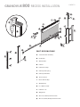
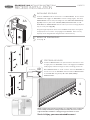
Retractable screens should always be installed square, plumb and level.
THE SCREEN FABRIC GETS BLOWN OUT OF THE SIDE TRACKS
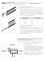
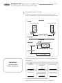
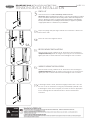
An Anti-Wind Brush Pile is located inside the B-Inside Rails. This Anti-Wind Pile is designed so that the
stiff bristles of the Brush Pile will engage inside the holes of the screen fabric as wind blows/pushes on
the fabric. Check that the aluminum walls of the B-Inside Rails have not been bent outward during
customer installation since this will prevent proper engagement. If needed take your thumb and
forefinger and gently run them along the length of the B-Inside Rails altering these back into a straight
90-degree position. This will reposition the Anti-Wind Pile so that it can perform as intended.
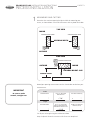
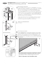
Be sure that the L-Pull Bar Lock engages the D-Pull Bar as shown in image [Fig 4C]. Using the height adjustment wheel on the
L-Pull Bar Lock, adjust the height to the appropriate level so that it easily engages the L-Pull Bar. When correctly adjusted the
latching and unlatching should be smooth and easy and the screen will stay latched until manually released.
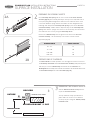
Check that the Anti-Wind Brush Pile has not been deformed or damaged and that it is still pointing in a 60 degree angle within
the B-Inside Rails.
Add an additional O-Weight Bar (or other ballast material) inside the D-Pull Bar.
Windy conditions may affect the performance of a retractable screen. Retract the screen in windy circumstances, during inclement
weather, when not needed to support immediate ventilation or during prolong periods when not used.
THE SCREEN IS DIFFICULT TO PULL DOWN OR UP
Check that the screen has been installed in a square and plumb opening. Adjust the opening as needed.
An Anti-Window Brush Pile is located just inside the B-Inside Rails. Gently run your finger or another soft object down each side
of the screen fabric in order to release the engagement of the Anti-Wind Brush Pile within the small openings in the Screen Fabric.
Now retract the screen.
Check and correct any interference (e.g. screws or debris) inside the B-Inside Rails.
Check that the D-Pull Bar glides smoothly. Slightly trim the aluminum D-PULL BAR if needed.
Check to see if the J-Weatherstrip is catching or binding in the B-Inside Rails
Remove the plastic Cassette End Cap from the operating side from the A-Screen Cassette Assembly and verify that the allen screw is
not fastened so tightly that it is restricting the operation.
Check that the tension device mounting screws have not loosened, and that the plunger is compressed far enough to allow the
chain to pass through it easily. Confirm that the mounting fasteners and anchors are appropriate for the substrate and replace if
necessary, and tighten the fasteners. If necessary, reposition the tension device slightly lower to provide additional clearance for the
chain to pass through it easily.
THE SCREEN DOES NOT RETRACT EVENLY
Check that the screen has been installed in a square and plumb opening. Correct the opening as needed.
Pull the screen all the way down to the bottom of the opening and then retract the screen. This will often help the screen fabric to
realign.
Pull the screen all the way down to the bottom of the opening. Look to see if there are creases in the fabric or other signs
indicating that the screen fabric may have rolled over itself inside the A-Screen Cassette Assembly. If needed remove the A-Screen
Cassette Assembly from the opening, extend (unroll) all of the screen fabric and then retract the fabric making sure to remove any
wrinkles or creases.
ANTI-WIND BRUSH PILE MOVES IN THE SIDE GUIDE RAILS
The Anti-Wind Brush Pile that is located inside the aluminum B-Inside Rails need to be crimped securely in place so that it does not
move within the channels of the B-Inside Rails (see step 4).
The L-PULL BAR LOCKS DO NOT CATCH ON THE D-PULL BAR
Adjust the height of the latch on the L-Pull Bar Locks using the wheel style finger adjustment. The engagement of the L-Pull Bar
Locks to the D-Pull Bar should match image 4C.
THE D-PULL BAR MOVES DURING WINDY CONDITIONS
Add an additional O-Weight Bar (or other ballast material) inside the D-Pull Bar.
Windy conditions may affect the performance of a retractable screen. Retract the screen in windy circumstances, during inclement
weather, when not needed to support immediate ventilation or during prolong periods when not used.
THE SCREEN IS TORN OR WRINKLED
The screen fabric has gotten bunched-up a bit in the screen Cassette. This can happen after a windy day or, if a person, animal or
object collides with the screen. When these things happen the edge(s) of the screen fabric can get pushed out of one or both of
the Side Guide Rails. If the screen is used without first positioning the edges of the screen fabric back fully inside the Side Guide
Rails, folds, creases and other damage can occur. In many cases where severe damage has not occurred then the issue can be
remedied as follows. Remove the Screen Cassette Assembly from the opening, extend (unroll) all of the screen fabric and then
retract the fabric making sure to remove any wrinkles or creases.
Contact dealer to order a Screen Refill Replacement Kit
THE J-WEATHER STRIP DOES NOT SEAL AGAINST THE FLOOR/SILL
Check that the screen has been installed in a square and plumb opening. Correct the opening as needed.
Contact dealer to order the slightly larger optional Seal.
Adjust the height of the latch on the L-Pull Bar Locks using the wheel finger adjustment. The engagement of the L-Pull Bar Locks to
the D-Pull Bar should match image 4C.
Add an additional O-Weight Bar (or other ballast material) inside the D-Pull Bar.
WHEN RETRACTED THE L-PULL BAR WITH SCREEN FABRIC FALLS DOWN SEVERAL INCHES
Add spring tension.
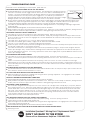
TROUBLESHOOTING GUIDE
Shorter Pile
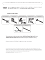
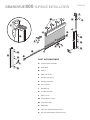
? Installation Questions ? Missing Parts ? Replacement Parts ?
Please call our Homeowner Helpline @ 1-888-483-3768
DON’T GO BACK TO THE STORE!
Installation Questions? Missing Parts? Replacement Parts?
DON’T GO BACK TO THE STORE!
Please call our Homeowner HelpLine: 1-888-483-3768
  • Page 1 1
  • Page 2 2
  • Page 3 3
  • Page 4 4
  • Page 5 5
  • Page 6 6
  • Page 7 7
  • Page 8 8
  • Page 9 9
  • Page 10 10
  • Page 11 11

LARSON GrandVue 800 User manual

Type
User manual

LARSON GrandVue 800 retractable screens provide insect protection and fresh air ventilation in low-wind conditions. They move in and out of a protective cassette, and the exposed surface area and edges of the fabric are flexible, making them suitable for low-wind conditions. To ensure longevity, retract the screen in windy conditions, during inclement weather, or when not in use for extended periods.

Ask a question and I''ll find the answer in the document

Finding information in a document is now easier with AI