Page is loading ...

SAVE THESE INSTRUCTIONS!
INSTALLATION INSTRUCTIONS
SAVE THESE INSTRUCTIONS!
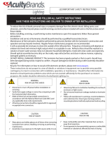
ELM2 LED
CAUTION: For safety and proper operation, read and follow instructions carefully before installation.
READ AND FOLLOW ALL SAFETY INSTRUCTIONS
SAVE THESE INSTRUCTIONS AND DELIVER TO OWNER AFTER INSTALLATION
WARNING: FAILURE TO FOLLOW THESE INSTRUCTIONS AND WARNINGS MAY RESULT IN DEATH, SERIOUS INJURY OR SIGNIFI-
CANT PROPERTY DAMAGE- For your protection, read and follow these warnings and instructions carefully before installing or maintaining this
equipment. These instructions do not attempt to cover all installation and maintenance situations. If you do not understand these instructions or
additional information is required, contact Lithonia Lighting or your local Lithonia Lighting distributor.
WARNING:
RISK OF ELECTRIC SHOCK- NEVER CONNECT TO, DISCONNECT FROM, OR SERVICE WHILE EQUIPMENT IS ENERGIZED.
WARNING: RISK OF FIRE- Lamps are hot. Keep combustible material away from hot parts. Observe lamp manufacturer’s warnings,
recommendations and restrictions on lamp operation and maintenance. Make sure lamps are correctly installed.
WARNING: DO NOT USE ABRASIVE MATERIALS OR OTHER SOLVENTS. USE OF THESE SUBSTANCES MAY DAMAGE FIXTURE,
WHICH MAY RESULT IN PERSONAL INJURY.
WARNING: RISK OF PERSONAL INJURY- This product may have sharp edges. Wear gloves to prevent cuts or abrasions when removing
from carton, handling, installing and maintaining this product (WHERE APPLICABLE).
• Before wiring to power supply, turn off electricity at fuse or circuit breaker.
• Disconnect AC power and unplug battery before servicing.
• Consult your local building code for approved wiring and installation.
• May be used outdoors under cover. (10°C- 40°C).
• Do not let power supply cord touch hot surfaces.
• Do not mount near gas or electric heater.
• Do not install a damaged fi xture.
• This product must be installed in accordance with the applicable installation codes and ordinances.
• Proper grounding is required to ensure peronal safety (WHERE APPLICABLE).
• All service shall be performed by qualifi ed service personnel. This product must be installed and maintained in accordance with the applicable
installation codes by a person familiar with the construction operation of the product and the hazards involved.
• Equipment should be mounted in locations and at heights where it will not readily be subjected to tampering by unauthorized personnel.
• The use of accessory equipment not recommended by the manufacturer may cause an unsafe condition.
• Do not use this equipment for other than intended use.
Patent # US: D473,672
D483,511
D484,272
® LED Series
IMPORTANT SAFEGUARDS

INSTALLATION INSTRUCTIONS
NOTE: This unit should be mounted ONLY through a pair of the preformed keyholes onto a 4” “OCTAGON” junction box, or
through a pair of the keyhole knockouts onto a 4” SQUARE junction box.
Feed the fi xture leads through the mounting plate and
make connections to AC power supply.
Use only Flexible Conduit with this
unit. Must be used with 4” j-box.
Dress the wires into the junction box. Secure the mounting
plate onto the junction box with a minimum of two screws.
NOTE: To ensure proper engagement of the snaps in the
mounting plate to the housing, DO NOT OVERTIGHTEN
SCREWS.
With AC power turned off, connect battery connector
leads.
CAUTION: Continuous AC power must be available
at time of installation as damage to the battery will occur
if the battery is connected to the charger board for more
than 3 days.
Align the holes on the bottom of the housing with the circular
snaps at the bottom of the mounting plate and push the
housing directly onto the mounting plate. (NOTE: Make
sure red battery wires are securely inside bat-
tery compartment prior to mounting housing
onto mounting plate.)
The two at the bottom, as well as the two hidden snaps at
the top should make an audible snap when fully engaged.
Apply continuous AC power and check that the test switch is
illuminated red, indicating proper function.

SAVE THESE INSTRUCTIONS!
INSTALLATION INSTRUCTIONS
SAVE THESE INSTRUCTIONS!
A. Normal Operation: When the unit is functioning properly, with power applied, the “TEST” switch will be illuminated
red.
B. To Test: Press the “TEST” switch. The fi xture will remain illuminated. When switch is released, the lamps will go off.
NOTE: See important battery information before testing.
INSTALLATION & MAINTENANCE
To Open Housing:
Press both circular snaps at the bottom of the hous-
ing. Lift the housing upward and pull it fi rmly away
from the mounting plate.
Lamp Replacement:
Disconnect the wire harness for the LED lamp board.
Unscrew the screws holding the LED lamp board to
the refl ector. Re-attach the new LED lamp board onto
the refl ector and connect the connector.
Charger Board Replacement:
Flex the snap at each end of charger board and pull
it straight out of the housing. Disconnect lamphead
wires from board and reconnect them to new board.
Slide charger board into place, make sure it is se-
cured by the snaps on both ends.
Lens Removal:
Using small straight blade tool, gently remove
the lens from the lamp head as shown above.
Battery Replacement:
Disconnect battery connector. Cut cable tie
and remove battery. Install new battery in
orientation as shown above. Reconnect battery
connector.
IMPORTANT BATTERY INFORMATION:
Allow battery to charge for 24 hours
before testing and fi rst use. Batteries
are perishable items. For best results,
it is recommended that the battery
receive an initial charge within the fi rst
3 years of the manufacture date of the
fi xture. The manufacture date can be
found on the outside of the unit pack-
aging and on the UL label as part of
the Date Code/Series.
Snaps
TEST
switch

INSTALLATION INSTRUCTIONS
WIRING DIAGRAMS
Part #EMCSA00764 Rev. F
2015.04.27
NOTE for HO models:
Use of 10-12 AWG stranded wire required to connect remote lamp heads to maintain operating voltage when remote fi xtures are connected to the emergency lighting equipment.
IMPORTANT CODE COMPLIANCE INFORMATION
In accordance with NFPA 101, documented testing of your emergency lighting system must be tested monthly for a minimum of 30 seconds and annually for 90 minutes. Refer to
your local codes for any additional requirements that may apply.
NOTE: Unused input
lead must be properly
insulated with wire
nut or other approved
method
One Lithonia Way, Conyers GA 30012
Phone: 800-334-8694
www.lithonia.com
/


