Page is loading ...

—
ABB MEASUREMENT & ANALYTICS | OPERATING INSTRUCTION
LS4000, LS4060
Diode laser analyzers
Version for measuring O
2
General purpose and
explosion-proof variants
Highest precision under
harshest conditions
Measurement made easy


LS4000, LS4060 DIODE LASER ANALYZERS | OI/LS4000/O2-EN REV. A 3
Contents
Preface .............................................................................................................................. 7
Safety instructions ......................................................................................................... 8
Description .................................................................................................................... 10
General Purpose variant: Description .......................................................................................................... 12
Specifications ................................................................................................................ 12
Labels .............................................................................................................................. 14
Scope of delivery ...........................................................................................................17
ATEX variant: Description ............................................................................................................................. 18
Specifications ................................................................................................................ 18
Safety rating .................................................................................................................. 20
Laser classification ...................................................................................................... 21
Labels for zone 1 ........................................................................................................... 22
Labels for zone 2 ........................................................................................................... 25
Scope of delivery .......................................................................................................... 28
IECEx variant: Description ........................................................................................................................... 30
Specifications ................................................................................................................ 30
Safety rating .................................................................................................................. 32
Laser classification ...................................................................................................... 33
Labels .............................................................................................................................. 34
Scope of delivery .......................................................................................................... 37
KCs variant: Description ...............................................................................................................................38
Specifications ................................................................................................................ 38
Safety rating .................................................................................................................. 40
Laser classification ...................................................................................................... 41
Labels .............................................................................................................................. 42
Scope of delivery .......................................................................................................... 45
CSA variant: Description .............................................................................................................................. 46
Specifications ................................................................................................................ 46
Safety rating .................................................................................................................. 48
Labels .............................................................................................................................. 49
Scope of delivery .......................................................................................................... 52
Preparing for installation .............................................................................................................................. 53
Explosion protection ................................................................................................... 53
Preparing the system .................................................................................................. 54
Preparing the installation site ................................................................................... 55
Process purging ............................................................................................................ 57
Laying out tools, installation materials and support materials .......................... 58
Determining cable runs and line runs ....................................................................... 59
Installing components .................................................................................................................................. 60
Option: Installing the insertion tubes ............................................................... 60
Providing an overview ................................................................................................. 60
Installing insertion tubes ............................................................................................ 61
Option: Installing the isolation flanges ..............................................................62
Providing an overview ................................................................................................. 62
Follow the safety information ................................................................................... 63
Installing the isolation flanges .................................................................................. 64
Installing the purging flanges ............................................................................. 66
Providing an overview ................................................................................................. 66

4 LS4000, LS4060 DIODE LASER ANALYZERS | OI/LS4000/O2-EN REV. A
Installing the purging flanges .................................................................................... 67
Roughly pre-aligning the purging flanges ............................................................... 68
Connecting the purging lines ..................................................................................... 72
Option: Installing the validation cell ................................................................... 73
Providing an overview ................................................................................................. 73
Installing the validation cell ........................................................................................ 74
Installing the transmitter unit and receiver unit ............................................... 75
Providing an overview ................................................................................................. 75
Installing the transmitter unit and receiver unit .................................................... 76
General Purpose variant: Electrical connections ........................................................................................ 78
Providing an overview ................................................................................................. 78
Observing cable specifications ................................................................................. 79
Protecting the line voltage supply ............................................................................ 80
Installing the junction box .......................................................................................... 80
Fitting the cable clips and line brackets .................................................................. 80
Selecting a suitable cable gland ................................................................................ 81
Leading cables through cable glands ....................................................................... 82
Connecting the electrical leads ...........................................................................83
Establishing a protective grounding ........................................................................ 83
Connecting the transmitter unit to the junction box ............................................ 84
Connecting the receiver unit to the junction box .................................................. 85
Option: Connecting the T/P probes to the junction box...................................... 86
Connecting the analog and digital outputs to the junction box ........................ 87
Connecting the potential equalization terminal .................................................... 88
Connecting the power supply .................................................................................... 89
ATEX variant: Electrical connections ........................................................................................................... 91
Providing an overview ................................................................................................. 91
Observing cable specifications ................................................................................. 92
Protecting the line voltage supply ............................................................................ 93
Installing the junction box .......................................................................................... 94
Fitting the cable clips and line brackets .................................................................. 96
Important notes on laying the cables and lines ..................................................... 96
Selecting a suitable cable gland ................................................................................ 97
Leading cables through cable glands ....................................................................... 98
Connecting the electrical leads .......................................................................... 99
Ensuring safety ............................................................................................................. 99
Establishing a protective grounding ........................................................................ 99
Connecting the transmitter unit to the junction box .......................................... 100
Connecting the receiver unit to the junction box ................................................ 101
Option: Connecting the T/P probes to the junction box.................................... 102
Connecting the analog and digital outputs to the junction box ...................... 103
Connecting the potential equalization terminal .................................................. 104
Connecting the power supply .................................................................................. 105
IECEx variant: Electrical connections ........................................................................................................ 107
Providing an overview ............................................................................................... 107
Observing cable specifications ............................................................................... 108
Protecting the line voltage supply .......................................................................... 109
Installing the junction box ........................................................................................ 110
Fitting the cable clips and line brackets ................................................................. 112
Important notes on laying the cables and lines .................................................... 112
Selecting a suitable cable gland ............................................................................... 113
Leading cables through cable glands ..................................................................... 114

LS4000, LS4060 DIODE LASER ANALYZERS | OI/LS4000/O2-EN REV. A 5
Connecting the electrical leads ......................................................................... 115
Ensuring safety ............................................................................................................ 115
Establishing a protective grounding ....................................................................... 115
Connecting the transmitter unit to the junction box .......................................... 116
Connecting the receiver unit to the junction box ................................................. 117
Option: Connecting the T/P probes to the junction box.................................... 118
Connecting the analog and digital outputs to the junction box ...................... 119
Connecting the potential equalization terminal .................................................. 120
Connecting the power supply ................................................................................... 121
KCs variant: Electrical connections ........................................................................................................... 123
Providing an overview ............................................................................................... 123
Observing cable specifications ............................................................................... 124
Protecting the line voltage supply .......................................................................... 125
Installing the junction box ........................................................................................ 126
Fitting the cable clips and line brackets ................................................................ 127
Important notes on laying the cables and lines ................................................... 127
Selecting a suitable cable gland .............................................................................. 128
Leading cables through cable glands ..................................................................... 129
Connecting the electrical leads ......................................................................... 130
Ensuring safety ........................................................................................................... 130
Establishing a protective grounding ...................................................................... 130
Connecting the transmitter unit to the junction box ........................................... 131
Connecting the receiver unit to the junction box ................................................ 132
Option: Connecting the T/P probes to the junction box.................................... 133
Connecting the analog and digital outputs to the junction box ...................... 134
Connecting the potential equalization terminal .................................................. 135
Connecting the power supply .................................................................................. 136
CSA variant: Electrical connections ........................................................................................................... 137
Providing an overview ............................................................................................... 137
Observing cable specifications ............................................................................... 138
Protecting the line voltage supply .......................................................................... 139
Installing the junction box ........................................................................................ 140
Fitting the cable clips and line brackets ................................................................ 141
Selecting a suitable cable gland .............................................................................. 142
Leading cables through cable glands ..................................................................... 143
Connecting the electrical leads ........................................................................ 145
Ensuring safety ........................................................................................................... 145
Establishing a protective grounding ...................................................................... 145
Connecting the transmitter unit to the junction box .......................................... 146
Connecting the receiver unit to the junction box ................................................ 147
Option: Connecting the T/P probes to the junction box.................................... 148
Connecting the analog and digital outputs to the junction box ...................... 149
Connecting the potential equalization terminal .................................................. 150
Connecting the power supply ................................................................................... 151
Gas analyzer start-up ................................................................................................................................... 153
Checking and approving for use ............................................................................. 153
Connecting the supply voltage ................................................................................ 156
Recognizing the operating status ........................................................................... 156
Connecting the PC to the junction box .................................................................. 157
Connecting to the instrument software ................................................................ 158
Menu structure of the instrument software ......................................................... 159
Main menu ................................................................................................................... 160

6 LS4000, LS4060 DIODE LASER ANALYZERS | OI/LS4000/O2-EN REV. A
System time menu ..................................................................................................... 161
Fine alignment of the purging flanges ................................................................... 162
Alignment menu.......................................................................................................... 164
Installation procedure ............................................................................................... 165
Installation – Process parameters menu ............................................................... 166
Installation – Installation flanges menu ................................................................. 168
Installation – Ambient conditions menu ................................................................ 170
Installation – External inputs menu ......................................................................... 171
Installation – Channels menu ................................................................................... 172
Installation – Analog and digital outputs menu ................................................... 173
Installation – Network settings menu .................................................................... 175
Installation – Save settings menu ........................................................................... 176
Maintaining and servicing the gas analyzer .............................................................................................. 177
Time schedule ...................................................................................................... 177
Continuous ...................................................................................................................177
As required ................................................................................................................... 178
Annual ........................................................................................................................... 180
Connecting to the instrument software ................................................................ 181
System information menu ........................................................................................ 182
Instrument status menu ........................................................................................... 183
Verification of I/O modules menu .......................................................................... 184
Diagnostics menu ....................................................................................................... 185
Service menu ............................................................................................................... 186
Spectrum menu .......................................................................................................... 187
Logging menu ............................................................................................................. 188
Validating and calibrating the gas analyzer ............................................................................................ 190
Validating the gas analyzer ............................................................................... 190
Preparing for validation ............................................................................................ 190
Validation ..................................................................................................................... 192
Calibrating the gas analyzer .............................................................................. 193
Installing the calibration set .................................................................................... 193
Adjusting the configuration ..................................................................................... 196
Calibration ................................................................................................................... 199
Calibration options menu ......................................................................................... 201
Calibration settings menu ........................................................................................ 202
Calibration menu ........................................................................................................ 203
Continuing measuring mode .................................................................................. 204
Recognizing and resolving errors .............................................................................................................. 205
Error messages in "Measuring" mode .................................................................... 205
Error messages in "Malfunction" status ................................................................206
Shutting down the gas analyzer ................................................................................................................ 209
Stopping use and shutting down the gas analyzer .............................................209
Disassembly................................................................................................................. 210

LS4000, LS4060 DIODE LASER ANALYZERS | OI/LS4000/O2-EN REV. A 7
Preface
This operating instruction contains all the information you need to install and
operate the analyzer in a safe manner and as intended.
In addition to this operating instruction, please also note the analyzer data
sheet that accompanies each analyzer.
Analyzer data sheet
The version of the delivered gas analyzer is described in the "Analyzer data
sheet" supplied with the gas analyzer.
DVD-ROM "Software tools and technical documentation"
The DVD-ROM "Software tools and technical documentation" with the follow-
ing contents is included in the scope of supply of the gas analyzer:
Software tools
Operating instructions
Data sheets
Technical information
Certificates
Internet
You will find information on ABB Analytical products and services online at
http://www.abb.com/analytical.
Service contact
If the information in this operating instruction does not cover a particular
situation, ABB Service will be pleased to supply additional information as
required. Please contact your local service representative. For emergencies,
please contact
ABB Service,
Telephone: +49–(0)180–5–222 580, Fax: +49–(0)621–381 931 29031,
E-mail: [email protected]
Indicates safety instructions that must be followed when handling
the analyzer in order to prevent danger to the user.
Indicates specific information on the operation of the analyzer as
well as on the use of this operating instruction.
1, 2, 3, … Indicate reference numbers used within figures.
Contents of the
operating instruction
Additional
information
Symbols, letters and
numbering used in
the operating
instruction

8 LS4000, LS4060 DIODE LASER ANALYZERS | OI/LS4000/O2-EN REV. A
Safety instructions
The analyzer is designed to measure gas concentrations in a gas mixture.
The analyzer is not designed or suitable for other purposes.
Any use for any other purpose is concerned an improper use.
The transmitter unit, receiver unit and junction box must be
properly grounded to prevent electrical hazards and disturb-
ances.
The glass lenses of the transmitter unit and the receiver unit
must be protected against mechanical influences.
The analyzer must only be installed in accordance with regional
and national regulations.
Installation and connection work must only be performed by
qualified personnel.
The analyzer must only be operated in accordance with regional
and national regulations.
Only genuine spare parts from the manufacturer may be used to
replace mechanical, electrical and optical components.
Only genuine spare parts from the manufacturer may be used to
replace mechanical, electrical and optical components.
The transmitter unit, receiver unit and junction box must not be
opened in the presence of an explosive atmosphere.
The transmitter unit, receiver unit and junction box must not be
disassembled in the presence of an explosive atmosphere.
Repairs to connection points on the transmitter and receiver unit
which are relevant to explosion protection are not allowed.
The ABB certificates regarding safety and electromagnetic com-
patibility relate to the transmitter unit, the receiver unit and the
junction box.
The ABB certificates regarding explosion protection relate to the
transmitter unit and the receiver unit. The current certificates
and safety instructions of the relevant manufacturer must be
observed with regard to the junction box and its installation.
These are available on the manufacturer’s website. Please refer
to the relevant data on the name plate of the junction box.
Intended use
Improper use
General safety
instructions
Safety when
installing and
connecting
Safety when
operating
Safety during
maintenance, service
and repair work
Safety when repairing
and disassembling
explosion-proof
variants
Certification of
analyzer components

LS4000, LS4060 DIODE LASER ANALYZERS | OI/LS4000/O2-EN REV. A 9
Risk of electric shock!
Classification Standard Degree of protection
Safety EN 61010 Protection class I
Safety of laser devices EN 60825-1 Laser class 1
Warning symbols on
the junction box
Applied safety
standards

10 LS4000, LS4060 DIODE LASER ANALYZERS | OI/LS4000/O2-EN REV. A
Description
Variant Type Certificate Power supply in
the junction box
General Purpose LS4000 Always installed
ATEX Zone 1 and Zone 2 LS4060 BVS 13 ATEX E 008 X Fitted or
not included
IECEx Zone 1 LS4060 IECEx BVS 13.0013X Fitted or
not included
KCs LS4060 15-AV4BO-0281,
15-AV4BO-0282
Not included
CSA Class I, Div. 1 & Div. 2,
CSA Class I, Zone 1
LS4060 12.2589676X Always installed
The certificates of the analyzer do not apply to the junction box of
the respective variant. When installing and operating the junction
box, please note the certificate and, if applicable, the operating
instructions of the relevant manufacturer.
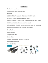
No. Meaning
1
Receiver unit
2
Transmitter unit
3
Process gas
4
Optical path length of the laser beam
5
Connection cable between receiver unit and junction box
6
Connection cable between transmitter unit and junction box
7
Junction box
8
Power supply
9
T/P probe(s)
10
PC
11
Analog and digital outputs
Analyzer variants
Analyzer design

LS4000, LS4060 DIODE LASER ANALYZERS | OI/LS4000/O2-EN REV. A 11
The analyzer consists of a transmitter unit and a receiver unit, which are in-
stalled opposite one another on a process line or stack and connected to each
other via a junction box.
The following components are connected to the junction box:
Transmitter unit and receiver unit
T/P probe(s) for dynamic temperature and pressure correction (depending
on application)
Power supply
Sensors for analog and digital outputs
Depending on design: External power supply unit (see Analyzer variants on
page 10)
A PC can be temporarily connected to the junction box for service purposes.
The LS4000 uses the optical measurement method of tunable diode laser
absorption spectroscopy (TDLAS), which is based on the fact that gases ab-
sorb light of specific wavelengths.
In this method, a configurable laser diode in the transmitter unit emits a laser
beam, which passes through the process gas and shines onto the photode-
tector in the receiver unit. The molecules of the measuring components locat-
ed in the optical path of the laser beam absorb the laser light, thereby reduc-
ing the light intensity at the receiver.
A sophisticated signal algorithm records the measured reduction in light in-
tensity and uses this value to calculate the gas concentration in accordance
with the Beer-Lambert law. The influence of temperature and pressure varia-
tions is eliminated by a dynamic automatic correction function.
Variant ABB P/N Manufacturer’s P/N
ATEX, IECEx, KCs without
power supply
758368 Bartec 07-5100-2002/3011
ATEX with power supply 758255 Bartec (Ex-e) 07-5180-2002/3011
Cortem (Ex-d) GUB-02
IECEx with power supply
758308 Bartec (Ex-e) 07-5180-2002/3011
Cortem (Ex-d) GUB-02
CSA Div. 1 with power supply 758219 R. Stahl 8264/6214-3210
Analyzer measuring
principle
Explosion-proof
variants of the
junction boxes
(manufacturer’s
part numbers)

12 LS4000, LS4060 DIODE LASER ANALYZERS | OI/LS4000/O2-EN REV. A
General Purpose variant: Description
Topic Page
Specifications ......................................................................................................... 12
Labels ...................................................................................................................... 14
Scope of delivery ................................................................................................... 17
Specifications
Specifications
Dimensions (W x H x D) 118 x 163 x 237 mm
Weight 4.1 kg each
Installation site Suitable for outdoor use
Ambient temperature Operation: −20 to +55 °C,
Storage: −40 to +70 °C
Relative humidity Up to 80 % at max. +31 °C,
linearly decreasing to 50 % at +40 °C
Operating voltage DC 24 V nominal (DC 18 to 32 V)
Total power consumption Max. 10 W
Housing protection type IP65
Protection class III
The General Purpose variant may be used for measuring a flammable gas
mixture, i.e. the laser beam may pass through a flammable gas mixture, if the
following conditions are met:
The laser beam must never pass through an explosive gas mixture.
The gas analyzer must be de-energized when an explosive gas mixture is
present.
When the laser beam shall pass through an explosive gas mixture, an explo-
sion-proof variant of the gas analyzer with type test certificate must be used.
Specifications
Dimensions (W x H x D) 300 x 200 x 155 mm
Weight 4.7 kg
Housing protection type IP65
Installation site Suitable for outdoor use
Ambient temperature Operation: −20 to +55 °C
Transmitter unit and
receiver unit
Gas mixture
Junction box

LS4000, LS4060 DIODE LASER ANALYZERS | OI/LS4000/O2-EN REV. A 13
Specifications
Operating voltage AC 100–240 V ± 10 %; 50 to 60 Hz
Power consumption 30 VA
Protection class I
Overvoltage category II
Degree of pollution 2
Safe isolation Safety extra-low voltage (SELV) on the low
voltage side
Overload protection Voltage and current limitation
Specifications
Analog outputs Three 4–20 mA outputs (one per measur-
ing component and for transmission), load
max. 500 Ω, not insulated
Analog inputs Two 4–20 mA inputs for dynamic process
temperature and pressure correction, load
max. 100 Ω, not insulated
Digital outputs Two outputs: 2-pin with N.O. contacts
30 V/1 A DC/AC; wired in accordance with
the requirements for class 2 circuits
1)
Service port Ethernet 10BaseT
1) Class 2 circuits are energy-limited circuits with a maximum voltage of
AC 30 V or 42 V, a maximum current of 5 A and a maximum power of
100 VA.
Safety in accordance with Euro-
pean standards – CE
Tested to EN 61010-1:2010
Safety in accordance with U.S.
and Canadian
standards – UL, CSA
The LS4000 and LS4060 gas analyzers are
certified for use in "General Purpose"
environments. They comply with the
standards CAN/CSA-C22.2 No. 61010-1-12
and UL Std. No. 61010-1 (3rd Edition).
EMC: Interference immunity Tested to EN 61326-1:2013
Inspection level: Industrial area, fulfills at
least the evaluation criteria according to
Table 2 of EN 61326-1.
EMC: Emission interference Tested to EN 61326-1:2013
Limit class B for interference field
strength and interference voltages is met.
The permissible environmental conditions for the transmitter unit
and receiver unit may differ from those of the junction box.
In such instances, compliance with the limit values of all modules
must be guaranteed by means of a suitable spatial arrangement
on site.
Power supply (in the
junction box)
Inputs and outputs
(in the junction box)
Safety and EMC

14 LS4000, LS4060 DIODE LASER ANALYZERS | OI/LS4000/O2-EN REV. A
Labels
No. Meaning
1
Name plate
2
Laser warning
The transmitter unit and receiver unit are each fitted with a name plate.
Transmitter unit and
receiver unit:
Position of labels
Transmitter unit and
receiver unit:
Deciphering name
plates

LS4000, LS4060 DIODE LASER ANALYZERS | OI/LS4000/O2-EN REV. A 15
No. Meaning
1
Details of the manufacturer
2
Model name
3
Transmitter unit, receiver unit
5
Permissible ambient temperature for operation
6
Supply voltage and power consumption
7
CE mark
8
CSA marking
9
EFUP marking (EFUP = environment friendly use period): 50 years
of operating time in accordance with the EU's RoHS Directive
without any leaks of substances hazardous to health or the envi-
ronment under normal conditions of use
10
Symbol: Consult operating instruction
11
Serial number, displayed as a bar code and in plain text
The transmitter unit and receiver unit are each fitted with a laser warning.
Meaning: Class I infrared laser beam invisible to the human eye.
Transmitter unit and
receiver unit:
Deciphering the laser
warning
Junction box:
Interpreting the
name plate

16 LS4000, LS4060 DIODE LASER ANALYZERS | OI/LS4000/O2-EN REV. A
No. Meaning
1
Details of the manufacturer
2
Model name
3
F-no. = Manufacturing number, A-no. = Order no.
4
Supply voltage and power consumption
5
Symbol: Consult operating instruction
6
CSA marking
7
EFUP marking (EFUP = environment friendly use period): 50 years
of operating time in accordance with the EU's RoHS Directive
without any leaks of substances hazardous to health or the envi-
ronment under normal conditions of use
8
CE mark

LS4000, LS4060 DIODE LASER ANALYZERS | OI/LS4000/O2-EN REV. A 17
Scope of delivery
Unpack all parts included in the scope of delivery.
Ensure that all delivered parts match your order.
Qty. Description
1 Transmitter unit with connection cable and protective cap for the lens
1 Receiver unit with connection cable and protective cap for the lens
1 Junction box, power supply unit fitted, cable glands pre-installed
1 Ethernet adapter
2 Purging flanges with seals and fastening clips (as per the order)
1 Analyzer data sheet (in the junction box)
1 Operating instruction
1 DVD-ROM "Software tools & technical documentation"
Accessories included as per customer order
Keep the transport packaging of the transmitter and receiver units for possi-
ble return. Keep the yellow protective caps of the lenses for service purposes.
Dispose of the residual packaging material in accordance with local regula-
tions.
Finally, check that all parts are complete and in perfect condition.
If … then …
all parts are in perfect condition the installation process can be started.
one or more parts are missing
or are not in perfect condition
the laser analyzer must not be installed.
Unpacking devices
and accessories
Identifying devices
and accessories
Disposing of
packaging material
Final check

18 LS4000, LS4060 DIODE LASER ANALYZERS | OI/LS4000/O2-EN REV. A
ATEX variant: Description
Topic Page
Specifications .........................................................................................................18
Safety rating .......................................................................................................... 20
Laser classification ............................................................................................... 21
Labels for zone 1 ................................................................................................... 22
Labels for zone 2 ................................................................................................... 25
Scope of delivery .................................................................................................. 28
Specifications
Specifications
Dimensions (W x H x D) 118 x 163 x 237 mm
Weight 4.1 kg each
Installation site Suitable for outdoor use
Operation only under atmospheric condi-
tions according to IEC 60079-0 (limited
temperature range, see below)
Ambient temperature Operation: −20 to +55 °C,
Storage: −40 to +70 °C
Relative humidity Up to 80 % at max. +31 °C,
linearly decreasing to 50 % at +40 °C
Operating voltage DC 24 V nominal (DC 18 to 32 V)
Total power consumption Max. 10 W
Housing protection type IP65
Protection class III
Specifications
Dimensions (W x H x D) 300 x 230 x 111 mm
Weight 4.5 kg
Housing protection type IP65
Installation site Suitable for outdoor use
Ambient temperature Operation: −20 to +55 °C
Specifications
Dimensions (W x H x D) 230 x 461 x 165 mm
Weight 10 kg
Housing protection type IP65
Installation site Suitable for outdoor use
Ambient temperature Operation: −20 to +55 °C
Transmitter unit and
receiver unit
Junction box
(without power
supply unit)
Junction box with
integrated power
supply

LS4000, LS4060 DIODE LASER ANALYZERS | OI/LS4000/O2-EN REV. A 19
Specifications
Operating voltage AC 100–240 V ± 10 %; 50 to 60 Hz
Power consumption 30 VA
Protection class I
Overvoltage category II
Degree of pollution 2
Safe isolation Safety extra-low voltage (SELV) on the low
voltage side
Overload protection Voltage and current limitation
Specifications
Analog outputs Three 4–20 mA outputs (one per measur-
ing component and for transmission), load
max. 500 Ω, not insulated
Analog inputs Two 4–20 mA inputs for dynamic process
temperature and pressure correction, load
max. 100 Ω, not insulated
Digital outputs Two outputs: 2 pin with N.O. contacts
30 V/1 A DC/AC; wired in accordance with
the requirements for class 2 circuits
1)
Service port Ethernet 10BaseT
1) Class 2 circuits are energy-limited circuits with a maximum voltage of
AC 30 V or 42 V, a maximum current of 5 A and a maximum power of
100 VA.
Safety in accordance with Euro-
pean standards – CE
Tested to EN 61010-1:2010
EMC: Interference immunity Tested to EN 61326-1:2013
Inspection level: Industrial area, fulfills at
least the evaluation criteria according to
Table 2 of EN 61326-1.
EMC: Emission interference Tested to EN 61326-1:2013
Limit class B for interference field
strength and interference voltages is met.
The permissible environmental conditions for the transmitter unit
and receiver unit may differ from those of the junction box. In such
instances, compliance with the limit values of all modules must be
guaranteed by means of a suitable spatial arrangement on site.
If the junction box is set up outdoors, measures must be taken
where necessary to ensure the intended operation. This may in-
clude rain canopies, for example, or housings with an adequate IP
rating.
Power supply (in the
junction box)
Inputs and outputs
(in the junction box)
Safety and EMC

20 LS4000, LS4060 DIODE LASER ANALYZERS | OI/LS4000/O2-EN REV. A
Safety rating
The specified explosion protection is only guaranteed when used
for its intended purpose.
The transmitter unit and receiver unit are certified for use in explosive atmos-
pheres as follows:
Classification Environment EC type examination
certificate
II 2(1)G Ex d [op is Ga] IIC T6 Gb Environment with
explosive gases
BVS 13 ATEX E 008X
II 2D Ex tb IIIC T88°C Db Environment with
explosive dusts
BVS 13 ATEX E 008X
The measurement function for the explosion protection is not the subject of
the EC type examination certificate.
The transmitter unit and receiver unit are certified for use in explosive atmos-
pheres as follows:
Classification Environment Certificate
II 3(1)G Ex d [op is Ga] IIC T6 Gc Environment with
explosive gases
BVS 13 ATEX E 008X
II 2D Ex tb IIIC T88°C Db Environment with
explosive dusts
BVS 13 ATEX E 008X
The junction box is certified for use in potentially explosive environments as
follows:
Classification Environment EC type examination
certificate
II 2G Ex e IIC T6 Gb
II 2G Ex d IIC T6 Gb
Environment with
explosive gases
PTB 11 ATEX 1016 X
DEKRA 13 ATEX 0209
II 2D Ex tb IIIC T80°C Db
II 2D Ex tb IIIC T80°C Db
Environment with
explosive dusts
PTB 11 ATEX 1016 X
DEKRA 13 ATEX 0209
Binding information: See name plate and manufacturer's EC type examination
certificate.
Preliminary remarks
Transmitter unit and
receiver unit:
Explosion protection
for zone 1
Transmitter unit and
receiver unit:
Explosion protection
for zone 2
Junction box: Safety
classification for zone
1 and zone 2
/