11
HARMONY • RIDE Technology self-contained
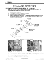
Install the louvered docking assembly.
Louvered docking assembly
4
DOCKING STATION: Horizon 700 water- and air-cooled models
(See detail drawing on page 12)
• Position and screw louvered docking assembly to the bottom of counter inside of access panel/
door 3.25" (82.55mm) from the front edge of the cross brace
➊
• The mounting surface for the louvered docking assembly must be solid.
Do not mount directly onto runners or channels.
• There must be no lip or edge that would hinder the icemaker from sliding in or out of the
louvered docking station
➋
INTAKE AND EXHAUST GRILLE PLACEMENT: Horizon 700 air-cooled models only
(See detail drawing on page 12)
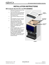
• Position the intake grille cut out in the access panel/door
Note: Icemaker must be aligned with cut out and inside of access panel to provide a tight seal
and prevent recirculation of hot exhaust air.
• Left edge of cutout should be 2" (51mm) from the left side of the icemaker
➌
• Bottom edge of cutout should be 2" (51mm) from the bottom of the icemaker
➍
• Position supplied exhaust grille at least 18" (458mm) away from intake grille
➎
.
Where possible, install exhaust grille to the rear or side of the base cabinet.
• If not using supplied grille, air circulation requirements below must be met:
700 series: 160 sq. in (1032 sq cm) intake/exhaust air
Undercounter installation requirements Horizon 700 series
4.1
WARNING
• Docking station must be secured in accordance with these instructions to ensure icemaker stability.
• Ventilation openings in the louvered docking station should be clear of obstruction. Failure to do so
could result in damage to equipment.
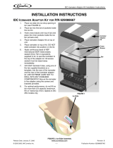
Machine stand accessory
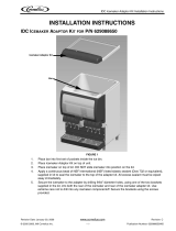
• Mount louvered docking assembly to wall
bracket accessory
• Mount louvered docking assembly to
machine stand accessory
Wall bracket accessory