Page is loading ...

After Serial Number L82638
Horizon Elite
™
Ice Machine Models with RIDE
®
Technology
Installation Instructions for Harmony
™
or
110CM Symphony
™
Plus Applications
HCD/HMD/HCF/HMF1010RHS, HCD/HMD/HCF/HMF1410RHS,
HCD/HMD1010NHS, HCD/HMD1410NHS
(See model number congurator on page 2 for details.)
remote condensing
01113232R02
801 Church Lane • Easton, PA 18040, USA
Toll free (877) 612-5086 • +1 (610) 252-7301
www.follettice.com
For applications using 110CM Symphony Plus
and most countertop dispensers manufactured by
Cornelius • Lancer • Servend

2
remote HARMONY and Symphony Plus • RIDE Technology
CAUTION!
§ This appliance should be connected by a qualied person in accordance with applicable codes.
§ If the supply cord is damaged, it must be replaced by the manufacturer, its service agent or similarly
qualied persons in order to avoid a hazard.
§ Connect to potable water supply only.
§ This appliance can be used by children aged 8 years and above and persons with reduced physical,
sensory, or mental capabilities, or lack of experience and knowledge if they have been given supervision
or instruction concerning use of the appliance in a safe way and understand the hazards involved. Children
should be supervised to ensure that they do not play with the appliance.
§ This appliance is intended to be used for household and similar applications such as staff kitchen areas
in shops, offices and other working environments; farm houses and by clients in hotels, motels and other
residential type environments; bed and breakfast type environments; catering and similar non-retail
applications.
§ WARNING! To avoid a hazard due to instability of the appliance, it must be xed in accordance with the
instructions.
ConfigurationApplication
S RIDE™
(RIDE remote
ice delivery
equipment)
T Top-mount
425 up to
425 lbs
(193 kg)
710 up to
675 lbs
(306 kg)
1010 up to
1061 lbs
(482 kg)
1410 up to
1466 lbs
(665 kg)
1810 up to
1790 lbs
(812 kg)
2110 up to
2039 lbs
(925 kg)
V Vision™
H Harmony™
B Ice storage bin
J Drop-in
M Ice Manager™
diverter valve
system
P Cornelius Profile
PR150
CondenserSeriesVoltageIcemaker
C 208-230/60/1 (icemaking head)
Self-contained only.
D 115/60/1 (icemaking head)
Self-contained and remote. If remote
unit, high side is 208-230/60/1.
E 230/50/1 (icemaking head)
Self-contained only.
F 115/60/1 (icemaking head)
Remote only. High side is
208-230/60/3.
MC Maestro™
Chewblet
®
(425 Series)
HC Horizon
Chewblet
(710, 1010, 1410,
1810, 2110
Series)
HM Horizon
Micro Chewblet™
HC 1810D SVA
A Air-cooled, self-contained
W Water-cooled, self-contained
R Air-cooled, remote condensing unit
N Air-cooled, no condensing unit for
connection to parallel rack system
Chewblet
®
Ice Machine Model Number Configurations

3
HARMONY and Symphony Plus • RIDE Technology remote
Front cover
8
Internal connection
7
Ice transport tube
5
External connection
6
Docking assembly
4
Dispenser preparation
3
Site preparation
2
Unpack
1
Read and complete the following 8 installation steps

4
remote HARMONY and Symphony Plus • RIDE Technology
Carefully unpack and inspect the contents of your Follett ice machine.
1
Unpack
7/16"
7/16"
➊
➋
➌
➍
➎
➏
➐
DO NOT TILT ICE MACHINE
TO ACCESS BOLTS!
COMPRESSOR DAMAGE
WILL RESULT
Unpack carton #1
1. 1

5
HARMONY and Symphony Plus • RIDE Technology remote
Prepare the installation site.
2
➎
➍
3/8" ∅ (9,5mm)
NEMA
5-15
➋
➊
➌
5/8" ∅ (15,8mm)
1" PVC Drain
2 ft. x 1" OD
silicone tubing
3/4" MPT x 1" slip
3/4" barb x 3/4" FPT
➌
1'
➌
1/4" per foot
(6,4 mm per 0,3 m)
Site preparation
Electrical
➊
• 1010(R/N)HS 120/60/1–5 amps
• 1410(R/N)HS 120/60/1–5 amps
Potable water supply
➋
(3/8" push-in internal connection, 3/8" OD tubing required)
• 10–70 psi (69–483 kpa)
• 45–90 F (7–32 C)
• Follett recommends the use of an in-line water ltration system (item# 00130286)
• This equipment is to be installed with adequate backow protection to comply with applicable
federal, state, and local codes
Drain
➌
(3/4" Barb)
• Minimum 8" radius on silicone drain line. Drain line from the ice machine must have at least
1/4" per foot pitch (6,4 mm/0,3 m).
Refrigeration lines
➍
and
➎
• 5/8" ∅ (15,8 mm) diameter suction line (insulated)
➍
• 3/8" ∅ (9,5 mm) liquid line
➎
2.1
Provide drainage, water supply and electrical power to within 6 feet (2m) of ice
machine in accordance with local and national codes. Outdoor installation of
low side is not recommended and will void warranty.
Installation site requirements
2.1

6
remote HARMONY and Symphony Plus • RIDE Technology
Prepare the dispenser.
3
Dispenser preparation
Attention! The location of the hole in the dispenser top is dependent
on the type of dispenser. Be sure to follow Step 3.1 for the
appropriate dispenser.
5"
(127 mm)
3.0" ∅
(77,2 mm)
Standard (Cornelius, Lancer, or Servend),
44" Lancer Sensation, and Pepsi Spire 4.1
Locate hole position 5" (127 mm) from back
of dispenser top
Back of Top
Front of Top
5"
(127 mm)
3.0" ∅
(77,2 mm)
5" (127 mm)
110CM Symphony Plus
Locate hole position 5" (127 mm) from
back and right of dispenser top
10.00"
9.00"
3.0" ∅
Locate hole position 10" (254 mm) from
back and 9" (229 mm) from right of
dispenser top
Back of Top
Front of Top
30" Lancer Sensation and Touchpoint
ø3"
hole saw
FRONT OF DISPENSER LID
(UNDERSIDE)
ø3.5"
hole saw
1
2
C
L
C
L
C
L
4
"
(102 mm)
ø3" hole location if using Horizon Ice
Machine with RIDE technology
ø3.5"
hole saw
REAR OF DISPENSER
LID (UNDERSIDE)
ø3.5" hole location if using Ice Manager
Diverter Valve System Sensor
Distribution Unit
Freestyle 9000
Hole location - Harmony (Lancer, Cornelius or Servend), or 110CM Symphony Plus
3.1
All others: If your dispenser is not listed or you need help with your installation, please
call our technical service group at (877) 612-5086 or +1 (610) 252-7301.

7
HARMONY and Symphony Plus • RIDE Technology remote
• Remove protective tape from gaskets
Top preparation
3.2
➋
➊
➌
➊
• Apply gaskets
➊
• Install shuttle actuator
➋
through
dispenser top and secure with locking nut
➌
Top preparation
3.3
➋
➊
• Screw 4" (102 mm) extension
➊
into
bottom of shuttle actuator
➋
Top preparation
3.4

8
remote HARMONY and Symphony Plus • RIDE Technology
PRESS IN ON
THIS SIDE TO
TURN SWITCH
ON.
PRESS IN ON
THIS SIDE TO
TURN SWITCH
OFF.
ROCKER
SWITCHES
(VIEW LOOKING
DOWN)
SWITCH
NUMBER
5
6
7
8
SWITCH
NUMBER
1 SECOND
3
4
OFF
OFF
150 MINS
ON
ON
ON
ON
AGITATION TIME
AGITATION FREQUENCY
OFF OFF OFF OFF OFF OFF OFF
SWITCH
OFF
SIDE VIEW
SWITCH
ON
SIDE VIEW
OFF
Lancer 4500 series only
Adjust the agitation time to 1 second, and the agitation frequency to 150 minutes. See Lancer
manual or call Lancer Customer Service at 1-888-846-6729 for more information.
Agitation adjustments – LANCER 4500 SERIES
3.6
54.543.5
3
2.5
2 1. 5
1
.5
3
HRS
2.5
HRS
2
HRS
1. 5
HRS
1
HR
30
MIN
MOTOR ON TIME:
SET TO 1 SECOND
MOTOR OFF TIME:
SET TO 1 HOUR
10
MIN
ON
TIME
OFF
TIME
E-BOARD AGITATOR TIMER
Cornelius models ED, DB, DF, IDC and FLAVOR FUSION
Adjust the agitation timer located on the Cornelius PC board to 1 second on, 1 hour off. Note: See
Cornelius manual or call Cornelius Technical Service at 1-800-238-3600 for more information.
Agitation adjustments – CORNELIUS
3.5
Agitation adjustments – LANCER Sensation and Touchpoint
3.7
No agitation adjustment required

9
HARMONY and Symphony Plus • RIDE Technology remote
Major/Minor
FS-16 Setup
Config Bonus Key
Soda/Plain Water
Config Dispense Only
PC Mode
PC Time
Ice Stir Off
Ice Stir On
Sold Out
Carb Sensors
Ice Bin Sensors
Valve Code Version
Number Of Valves
Reset Defaults No Ye s
Reload Defaults?
1 2 3 4
12 0.104 0.104
1000
Ice Bin Optic
Upper Lower
Sold Out #1
Selection Sold Out
05000
On Time (MSEC)
Off On
Set PC Mode Menu
V:1 B1 DLY1
Dispense Delay
V:2 1:S 2:W 3:S 4:W
V:1 T:F M:S B:W
Bonus Key Setup
Brands Per Side
V:1 L:2 R:1
FS-16 Setup
FS-16 Setup
FS-16 Setup
FS-16 Setup
FS-16 Setup
FS-16 Setup
FS-16 Setup
FS-16 Setup
FS-16 Setup
FS-16 Setup
FS-16 Setup
FS-16 Setup
FS-16 Setup
Soda/Plain Water
OFF Time (MIN)
00150
On Time (MSEC)
01000
1000 500
34 0.104 0.104
On On On On
V:1 B:1
Sold Out #1
Off
Sold Out #1
Ver. 0.200
Lancer FS-16
Sub-CatagoryMain Menu
Initialization Screen
2nd Sub-Catagory
(Boot Up Only)
Cancel
Enter
Scrolls through Main Menu
Press "Enter" to enter sub-catagory
Moves curser to right or left
Changes value (number/letter)
Press "Enter" to enter save changes
Press "Cancel" to exit menu
➊
Lancer FS series only
• Hold down “cancel" and “left button" to get to hidden menu
➊
• Type in code 6655
• Type in 150 minutes “off time" and 1010 milliseconds (1 second of time) as the preferred setting
Note: See Lancer manual or call Lancer Customer Service at 1-888-846-6729 for more information.
Agitation adjustments – LANCER FS SERIES
3.8
Agitation adjustments – SERVEND
3.9
Servend models only
No agitation adjustment required
Agitation adjustments – Coke Freestyle 9000
3.10
Call Coca-Cola at 800-241-COKE (2653) and request a Freestyle Senior Tech.

10
remote HARMONY and Symphony Plus • RIDE Technology
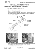
P/N 307277 — Diverter plate
(single agitator Cornelius
dispensers and left-hand
dispense chute on dual-agitator
Cornelius dispensers)
P/N 307277 — Diverter plate
(single agitator Cornelius
dispensers and left-hand
dispense chute on dual-agitator
Cornelius dispensers)
Single Agitator
Dual Agitator
P/N 00996207 — Diverter plate
(right-hand dispense chute on
dual-agitator dispensers)
Dispenser diverter plate overview – CORNELIUS ED, DF and DB SERIES
(Installation on next page)
3.10

11
HARMONY and Symphony Plus • RIDE Technology remote
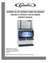
ICE CHUTE
GATE MOUNTING PLATE
GASKET
STORAGE HOPPER
ICE DIVERTER
10-32 WASHER
10-32 NUT
FLANGE EXTENDS INTO
STORAGE HOPPER
THROUGH GATE
OPENING
APPLY RTV TO THIS
SURFACE TO SEAL
TO HOPPER GATE
MOUNTING PLATE
ICE CHUTE
COVER
Cornelius ED, DF and DB series only
These dispensers require the installation of an ice diverter at the dispenser opening.
• Disassemble chute assembly
• Discard factory restrictor plate
• Replace with alternate diverter plate (supplied)
Dispenser diverter plate installation – CORNELIUS ED, DF and DB SERIES
3.11
Agitation adjustments – Cornelius IDC and Flavor Fusion
3.12
These dispensers require modications for compatibility with Chewblet ice. Agitation
times must be set to 1 second ON, 1 hour OFF and the ice restrictor plate must
be adjusted to the fully open position. See your beverage supplier for these
modications.

12
remote HARMONY and Symphony Plus • RIDE Technology
3/8˝ ∅
high pressure
line
1010, 1410:
5/8" ∅ low pressure line
1" (25,4 mm)
Stub Typ
1.88" (47,8 mm)
3.38" (86 mm)
2" (50,8 mm)
➋
➊
➊
Install the docking assembly.
Docking assembly
4
• Mount docking assembly
➊
• “Rough-in" the refrigerant piping
➋
2.1
Docking assembly
4.1
Machine stand accessory
Wall bracket accessory
• Mount docking assembly to wall bracket
accessory
• Mount docking assembly to machine
stand accessory
Prior to installing the docking assembly, ensure that the drain tting
is oriented (right or left) correctly for your installation. An optional
straight drain tting is also supplied. You may need to remove the
back panel of the docking assembly in order to re-orient or change
the drain tting. Replace back panel prior to mounting the docking
assembly.
BEFORE PROCEEDING

13
HARMONY and Symphony Plus • RIDE Technology remote
No Lip
➋
Access panel/
door on counter
3.25" (83 mm) min.
➊
➌
24" min.
(609 mm
22.25" min.
(656 mm)
CROSSBRACE
Top View
DOCKING STATION
• Prior to installing the docking assembly, ensure that the drain tting is oriented (right or left)
correctly for your installation. An optional straight drain tting is also supplied. You may need to
remove the back panel of the docking assembly in order to re-orient or change the drain tting.
Replace back panel prior to mounting the docking assembly.
• Position and screw docking assembly to the bottom of counter inside of access panel/door min.
of 3.25" (83 mm) from the front edge of the cross brace
➊
• The mounting surface for the docking assembly must be solid.
Do not mount directly onto runners or channels.
• There must be no lip or edge that would hinder the ice machine from sliding in or out of the
docking station
➋
• Ice machine must be installed facing forward as shown for service accessibility
➌
Undercounter installation requirements
4.2

14
remote HARMONY and Symphony Plus • RIDE Technology
Transport tube
Install the transport tube.
5
➋
1/4"
1'
➌
➑
➒
➓
➊
Hot Water
160 F (71 C)
➍
➏
➐
➎
Ice transport tube tips
• Insulate entire length of ice transport tube
➊
• Secure ice transport tube
➋
as needed to prevent dips and traps from forming.
For long tube runs see guide on page 19.
• Pitch ice transport tube at least 1/4" per foot (6,4 mm/0,3 m)
➌
• Ice transport tube must drain towards ice machine
Ice transport tube to dispenser
• Be sure tube ends are square
➍
• Heat end of transport tube in cup of 160 F (71 C) hot water to soften and spread with pliers
➎
before making connection to ease assembly
• Push ice transport tube onto shuttle actuator nipple
➏
• Install hose clamp
➐
Ice transport tube to Ice machine
• Be sure tube ends are square
➑
• Heat end of transport tube in cup of 160 F (71 C) hot water to soften and spread with pliers
➎
before making connection to ease assembly
• Push transport tube onto ice machine nipple
➒
• Install hose clamp
➓
Transport tube installation.
5.1

15
HARMONY and Symphony Plus • RIDE Technology remote
Connect utilities to docking assembly.
6
External connections
3/4" barb x 3/4" FPT
1" Stand pipe/Drain
2 ft. x 1" OD
silicone tubing
Minimum 8"
radius
➍
3/4" MPT x 1" slip
➎
➌
➋
➊
➏
• Rough-in ice machine potable water
supply
➊
.
3/8" push-in connection will be made at
shut-off valve inside machine
• Remove access panel if necessary
➋.
• Connect the silicone tubing to the ice
machine 3/4" drain barb
➌
.
• Assemble the 3/4" barb x 3/4" FPT to the
3/4" MPT x 1" slip. Connect the other end
of the silicone tubing to the 3/4" barb
➍
.
• Connect the 1" slip tting to the 1" stand
pipe/drain
➎
.
Note: Minimum 8" radius on silicone
drain line. Drain line from the ice machine
must have at least 1/4" per foot pitch
(6,4mm/0,3m).
• Apply Petrol-gel to barbed drain tting
➏
• Replace access panel.
Water and drain
6.1
➊
• Braze supplied quick-connect lines onto
stub-ins
➊
.
Refrigerant lines
6.2

16
remote HARMONY and Symphony Plus • RIDE Technology
Connect docking assembly to ice machine.
7
Internal connections
➊
➋
• Slide ice machine into docking assembly
ensuring that drain tube is fully seated on
barbed drain tting
➊
• Insert ice transport tube all the way into
coupling and tighten nut rmly
➋
Ice transport tube installation
7. 1
➋
➊
• Insert potable water line into valve
➊
Water line
7. 2
• Remove twist tie
• Carefully pass cord through opening and
plug into wall outlet
Power cord
7. 4
Refrigeration lines
7. 3
➊
• Evacuate line set.
• Connect self-sealing liquid and suction
line ttings
➊

17
HARMONY and Symphony Plus • RIDE Technology remote
• Position plate into opening and secure
with supplied screw
Power cord
7. 5
CLEANER FULL
DRAIN CLOG
HIGH PRES
HIGH AMPS
SERVICE
MAINT/CLEAN
LOW WATER
TIME DELAY
SLEEP CYCLE
MAKING ICE
LOW BIN
POWER ON
CLEAN
TDS
HIGH
LOW
• Set the TDS switch on the electrical box:
HIGH: for extended service life
LOW: for low-scale water
TDS switch
7. 6

18
remote HARMONY and Symphony Plus • RIDE Technology
Front cover
Install front cover to ice machine.
8
• Complete installation of condensing unit
or connection to rack system.
• Required rack system capacity at 0 F
(–18C) evaporator (EPR supplied by
installer).
1010N: 7,700 Btu/hr (1940 kcal/hr)
1410N: 10,000 Btu/hr (2519 kcal/hr)
Install condensing unit
8.1
NOTICE
Ice machine MUST be sanitized prior to operation!
Consult Operation and Service Manual provided with ice machine for sanitizing instructions.
➋
➊
• Slide ice machine cover over machine
➊
• Insert and tighten two screws through
cover and into docking assembly
➋
Install ice machine front cover
8.2

19
HARMONY and Symphony Plus • RIDE Technology remote
➊
➋
1/4"
1'
max. 2 ft (.6m)
• Pitch ice transport tube to allow melt water to drain towards ice machine
➊
• Secure insulated ice transport tube at least every 2 ft (0,6 m) to prevent dips or traps
➋
Long tube run recommendations

01113232R02
© Follett LLC 11/20
801 Church Lane • Easton, PA 18040, USA
Toll free (877) 612-5086 • +1 (610) 252-7301
www.follettice.com
Maestro, Micro Chewblet, Vision, Harmony, Ice Manager, Horizon, Horizon Elite are trademarks of Follett Products LLC.
Chewblet, RIDE, Follett are registered trademarks of Follett Products LLC.
/