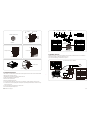
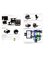
Magellan MHI1-548 is a bidirectional inverter which can convert direct current into alternating current. The output of the inverter can be used to power appliances, charge batteries, or feed back into the grid. The inverter has a built-in MPPT solar charger, which allows it to convert power from solar panels into usable electricity. The inverter also has a built-in battery charger, which allows it to charge batteries from the grid or from solar power. The inverter can be used in both on-grid and off-grid applications.
Magellan MHI1-548 is a bidirectional inverter which can convert direct current into alternating current. The output of the inverter can be used to power appliances, charge batteries, or feed back into the grid. The inverter has a built-in MPPT solar charger, which allows it to convert power from solar panels into usable electricity. The inverter also has a built-in battery charger, which allows it to charge batteries from the grid or from solar power. The inverter can be used in both on-grid and off-grid applications.


-
 1
1
-
 2
2
-
 3
3
-
 4
4
-
 5
5
-
 6
6
-
 7
7
-
 8
8
-
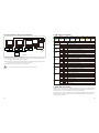 9
9
-
 10
10
-
 11
11
-
 12
12


Magellan MHI1-548 is a bidirectional inverter which can convert direct current into alternating current. The output of the inverter can be used to power appliances, charge batteries, or feed back into the grid. The inverter has a built-in MPPT solar charger, which allows it to convert power from solar panels into usable electricity. The inverter also has a built-in battery charger, which allows it to charge batteries from the grid or from solar power. The inverter can be used in both on-grid and off-grid applications.
Ask a question and I''ll find the answer in the document
Finding information in a document is now easier with AI
Related papers
Other documents
-
 Ampeak 8542130508 User guide
-
 Ampeak 13 User guide
-
Martin VC-Grid 30 Template
-
INVT XD5-12KTR Three-phase Hybrid Inverter User manual
-
-
Growatt SPH3000 User manual
-
-
-
Growatt Sungold 1000 Installation & Operation Manual
-

