Page is loading ...

1
© Copyright 2007 Printed
Before You Start
Your Lift Motor, Snow Blade is exclusively designed for
your Land Pride NT & ST Treker. Please read these
installation instructions and your NT & ST Treker
Operator’s Manual thoroughly before beginning.
Especially read information relating to safety concerns.
Also included in the Operator’s Manual is important
information on operation, adjustment, troubleshooting,
and maintenance for this attachment (some manual
sections do not apply to all accessories).
General Information
These assembly instructions apply to the following Lift
Motor, Snow Blade Accessories listed below:
701-069A Lift Motor, Snow Blade
Further Assistance
Your dealer wants you to be satisfied with your new Lift
Motor, Snow Blade. If for any reason you do not
understand any part of this manual or are not satisfied
with the service received, the following actions are
suggested:
1. Discuss the matter with your dealership service
manager making sure he is aware of any problems
youmay haveand that hehas had theopportunity to
assist you.
2. If you are still not satisfied, seek out the owner or
general manager of the dealership, explain the
problem and request assistance.
3. For further assistance write to:
Land Pride Service Department
1525 East North Street
P.O. Box 5060
Salina, Ks. 67402-5060
E-mail address
lpser[email protected]
When you see this symbol, the subsequent
instructions and warnings are serious - follow
without exception. Your life and the lives of
others depend on it!
!
IMPORTANT: Before you begin, read these
instructions and check to be sure all parts and tools
are accounted for. Please retain these installation
instructions for future reference and parts ordering
information.
THANK YOU FOR YOUR PURCHASE OF OUR SNOW
PLOW
ENCLOSED IN THIS KIT IS THE UNIVERSAL
ELECTRIC LIFT HARDWARE 701-069A
TO HAVE A COMPLETE PLOW ASSEMBLY, YOU
MUST HAVE AT LEAST FOUR BOXES:
1. MODEL SPECIFIC ATTACHING HARDWARE KIT.
TO ATTACH UNIVERSAL PUSH TUBE TO
MACHINE.
2. UNIVERSAL PUSH TUBE
3. BLADE OF YOUR CHOICE (COLOR, STYLE, &
SIZE)
4. YOUR CHOICE OF BLADE LIFT METHODS,
A. ELECTRIC BLADE LIFT
B. USE YOUR WINCH TO RAISE AND LOWER YOUR
BLADE.
OPERATING INSTRUCTIONS READ BEFORE
OPERATING
CUSTOMER MUST RECEIVE COPY OF OPERATING
INSTRUCTIONS AT TIME OF SALE.
!
DANGER
Exercise EXTREME CAUTION when plowing and always
at a slow speed.
!
WARNING
TO AVOID SERIOUS INJURY OR DEATH:
1. DO NOT EXCEED 5 MPH WITH BLADE
INSTALLED.
2. OPERATE WITH EXTREME CAUTION ON
SLOPES, STEEP GRADES AND ROUGH
TERRAIN.
3. KEEP AWAY FROM BLADE AND MOVING PARTS
DURING OPERATION.
4. WHEN PLOWING SNOW OR DIRT INTO A PILE
START BACKING UP BEFORE RAISING THE
BLADE.
5. DO NOT RAM THE BLADE INTO THE PILE. **
SLOW DOWN BEFORE HITTING PILE. **
6. BE AWARE OF POSSIBLE HIDDEN OBJECTS
UNDER SNOW.
Treker NT & ST TrekerSeries
Lift Motor, Snow Blade
Assembly Instructions
06/21/07
Manual No. 701-149M

2
Manual No. 701-149M 06/21/07
Land Pride
Assembly Instructions
■
!
CAUTION
TO AVOID PERSONAL OR OTHER INJURY:
1. READ BLADE OWNER’S MANUAL, MACHINE’’’S
OPERATOR’S MANUAL, AND SAFETY DECALS
BEFORE OPERATING.
2. WEAR HEAD PROTECTION, SAFETY GLASSES,
AND SHOES AS RECOMMENDED IN ATV
OPERATOR’S MANUAL.
3. ALLOW NO RIDERS ON BLADE OR MACHINE
WHILE MOVING OR STATIONARY.
4. KEEP BYSTANDERS AWAY FROM BLADE AND
ATV WHILE MOVING OR STATIONARY.
5. BEFORE ADJUSTING BLADE ANGLE, STOP THE
MACHINE’S ENGINE, SET AND LOCK BRAKES,
RAISE BLADE. DO NOT ATTEMPT TO RAISE
BLADE BY HAND; USE THE LIFT ONLY.
6. BEFORE ADJUSTING BLADE HEIGHT: LOWER
BLADE TO THE DOWN POSITION.
7. WHEN BLADE IS NOT IN USE, STOP THE
MACHINE’S ENGINE, SET AND LOCK BRAKES,
AND LOWER BLADE TO DOWN
!! ! OPERATION! ! !
** Your blade and hardware were designed with your
safety in mind. In order to protect you and your machine,
certain parts of the blade and / or hardware are designed
to fail when the equipment is over stressed. For this
reasonPush Tubes, Blade Hinges, Push Plate Attaching
Pins and Clevis Pins are not covered by Warranty.
* Blade angle is adjustable. Raise blade. To move the
blade left, right or straight, pull the Blade Position Lever
ahead and turn the blade to the desired position. The
Lever will spring back when the blade is at the correct
angle.
* The blade skids are adjustable so the blade can be
lowered but still held a certain distance off the ground.
*Theblade is designed to trip whenitstrikes an object or
digs in too far. When pressure is released the blade
springs back into position. Blade spring tension may be
set stiffer by tightening the Locknuts on the bottom of the
Eyebolts. For less spring tension, loosen the Locknuts.
* Do not exceed 5 MPH with blade installed.
* Operate with extreme caution on slopes, steep grades
and rough terrain.
* Keep away from blade and moving parts during
operation.
!
WARNING
! Due to reduced ground clearance, remove plow Mount
Brackets before trail riding.
! Do not exceed 5 MPH with the blade or its brackets
installed
OPERATION TIPS
Whenplowingsnowordirtintoapile,back awayfrom the
pile before attempting to raise the blade
!For best results set the suspension to the stiffest setting
if possible
! The Blade is shipped with the Blade Skids mounted
upside down for boxing. Be sure to mount the Skids
properly before using your blade.
MAINTENANCE
! Periodically check for wear and tightness of all bolts,
nuts and fasteners. Replace or tighten as necessary.
NOTICE
! The use of Blade Lift Kits Not Manufactured by Land
Pride with Work Power Blades will void all warranties.
! The Land Pride Blade Lift Kits are specifically designed
to help prevent damage to the Blades, Lift Kits and the
machine.
! PREPARATION:
Using the Parts List and Parts Drawing included, verify
that you have received all the components of the 701-
069A Electric Lift Kit.
NOTE: The MACHINE needs to be on a level surface.
All directions referring to the right and the left are when
the operator is sitting on the machine.
Numbers in parenthesis refer to item numbers on the
parts list and parts drawing at the end of the instructions
Assembly Instructions
Adetailedlistingofpartsfor thisaccessory kitisprovided
on page 6. Use the list as a checklist to inventory parts
received.Pleasecontact your local Land Pride dealer for
any missing hardware.
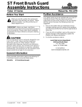
Using the two 3/8" x 1" bolts (#12) and Nylock Nuts
supplied,securelyfastentheElectricLiftAssemblytothe
U608 Blade Position Lever Bracket as shown below.

3
06/21/07
Manual No. 701-149M
Assembly Instructions
Land Pride
■
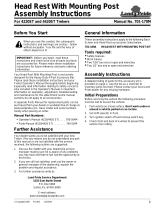
Attach the Lift Strap (#6) to the front of the machine. The
Strap needs to be secured to the machine in such a
manner that it will support the Blade and be as close to
straight above the Cable Spool of the Electric Lift as
possible. Have the end of the Lift Strap (#6) be roughly
20" above the ground.
Attach the 3/16" Quick Link (#8) to the end of the Lift
Strap as shown. Do not attach the cable at this time.

4
Manual No. 701-149M 06/21/07
Land Pride
Assembly Instructions
■
Switch Installations
Choose a place for the switch assembly that is free
from obstructions and does not interfere with the
normal functions of the machine.
Method One:
Place the 13/16 Vinyl Coated Cable Clamp (#16) around
machine’s front rack and secure using one 10-3/4" Pan
head Bolt (#19), #10 Star Washer (#17), 5mm Flat
Washer (#18), 10-24 Nylock Nut.
Method Two:
This method you will not use the Switch Housing (#14).
Locate a convenient place on the dash to mount the
switch.Cut a rectangular hole 7/8" x 1".Press the switch
into the rectangular hole. See picture below.
Route the Red and Black wires to the battery.
These wires must be well clear of any moving parts on
the machine
Do not allow the wires to come in contact with any hot
parts of the machine, such as the exhaust or cylinder
head.
Secure the ring terminal on the black wire to the battery
negative post.
Install the ring terminal on the red-white wire to the
positive battery terminal.
Route the red and brown leads of the Wiring Harness
(#27) to the front of the machine and connect to the lift
motor plug.
Thesewires mustbewell clearofanymovingparts ofthe
machine
Do not allow the wires to come in contact with any hot
parts on the m achine such as the exhaust or cylinder
head
Allow plenty of slack for vertical movement of the plow
between the tie point on the machine and the electric lift
motor.
Plug the Relay (#13) into the relay socket on the Wiring
Harness (#12).
With a 12-volt test light or meter locate a wire that is only
hot when the ignition switch is in the "on" position.
Use the blue scotch lock (#22) tap connector to connect
the yellow wire from the electronic module to this wire.
Note: Failure to connect the yellow wire to a wire that is
energized only when the ignition switch is in the "on"
position, will discharge the battery.
Check your electrical connections and make sure there

5
06/21/07
Manual No. 701-149M
Assembly Instructions
Land Pride
■
is a fuse in the fuse holder. Turn the key switch to the on
position and test run the lift motor by pressing the up
button on the handlebar switch.
Verify that pressing the up button on the handle bar
switch causes clockwise rotation of the spool when
viewed from the open end. (See illustration below). If the
spool rotates counterclockwise, see the note on the
electric lift
wiring harness diagram on the previous page. The spool
should now rotate in the clockwise direction when
pressing the top button.
Run the spool in the direction necessary to end up with
one wrap of cable on the spool and the cable to the front
side of the spool.
Withtheblade resting on the ground, route the end of the
cable up through the quick link (#8) in the lift strap (#6),
and secure it with the Cable Clamp (#7).
NOTE: If the Blade is raised too high, the Push
Tube will contact the ATV frame and put an
excessive load on the Gear Motor and other parts.
Failure of the fuse may result. Stop the blade at a
point before this contact occurs.
ALSO: Be aware that if the switch is held in the
"DOWN" position after the Blade has contacted the
ground, the cable will start to wind up backwards on
the Spool.
A drop of oil on each end of the spool will keep the
spool lubricated. Do this periodically

Land Pride
Listing of Parts
Manual No. 701-149M 06/21/07
6
■
1 EL100B GEAR MOTOR 1
2 EL120 GEAR PULLEY 1
3 EL121A MOTOR MOUNT PLATE 1
4 EL113 1 1/4" SPACER 4
5 EL122A BRG PLATE 1
6 PUR1481 LIFT STRAP 1
7 CC18 1/8" CABLE CLAMP 1
8 U605 3/16" QUICK LINK 1
9 EL123 36" CABLE 1
10 EL124 O-RING 1
11 802-152C HHCS 1/4-20X2 GR5 2
12 802-017C HHCS 3/8-16X1 GR5 2
13 ELRELAY RELAY 1
14 WNRSHOUSING SWITCH HOUSING 1
15 WNRSWITCH-3 R-3 SWITCH 1
16 CVC1316 13/16" CABLE CLAMP 1
17 SW10 #10 STAR WASHER 1
18 FW5MM 5 MM FLAT WASHER 1
19 801-021C SCREW RD HD 10-24 X 3/4 PLT 1
20 800-112C CABLE TIE .19X7.25 1.75D 50LB 1
21 839-288C 20 AMP FUSE (5 PACK) 1
22 SCOTCHLOCK SCOTCH LOCK 1
23 EL136 O-RING 1
24 EL119 ELECTRIC LIFT PIG TAIL 1
25 STS10-212 #10 2-1/2" SELF TAPPING SCREW 2
27 EL137 WIRING HARNESS 1
28 801-172C SCREW HEX 1
Kit No. 701-069A ELECTRIC LIFT KIT
Item Part No. Part Description Qty
/