Page is loading ...

properly. Do not use a compressed
air source capable of more than 200
PSI. The nailer could explode and
cause death or serious personal
injury.
● Never use gasoline or
other flammable liq-
uids to clean the nail-
er. Never use the nail-
er in the presence of
flammable liquids or
gases. Vapors could ignite by a spark
and cause an explosion which will
result in death or serious personal
injury.
● Always place
yourself in a
firmly balanced
position when
using or han-
dling the
nailer.
● Do not modify
or disable the
Work Contact
Element (WCE)
in a depressed
position or tape
or modify the
trigger in a pulled position. Death or
serious personal injury will occur.
● Never keep the
trigger pulled
when carrying
or holding the
nailer. Make
sure not to pull
the trigger or
depress the
work contact element (WCE) trip
mechanism when connecting the
nailer to an air compressor. Death or
serious puncture wounds will occur
if the work contact element (WCE)
bumps something.
Finishing Nailer
Please read and save these instructions. Read carefully before attempting to assemble, install, operate or maintain the product described.
Protect yourself and others by observing all safety information. Failure to comply with instructions could result in personal injury, death
and/or property damage! Retain instructions for future reference.
General Safety Information
This manual contains safety, operational
and maintenance information.
Read this manual and
understand all safety
warnings and instruc-
tions before operating
the nailer. Contact your
Campbell Hausfeld rep-
resentative if you have any questions.
The operator of this nailer must take
the necessary precautions to prevent
unsafe conditions outlined in this manu-
al from occurring. The operator is also
required to read and understand this
instruction manual and all safety warn-
ings, labels, etc.
Any employer allowing the use of this
nailer in their field of work must dis-
tribute this instruction manual to all
users. The employer must also ensure
all users read, understand and follow
the instructions as described in the
manual, safety warnings, labels, etc.
Danger indicates
an imminently
hazardous situation which, if not
avoided, WILL result in death or serious
injury.
● Do not use any type
of flammable gases
or oxygen as a power
source for the nailer.
Use filtered, lubricat-
ed, regulated com-
pressed air only. Use
of a compressed gas instead of
compressed air may cause the nailer
to explode and cause death or
serious personal injury.
● Do not exceed maxi-
mum operating pres-
sure of the nailer
(110 PSI). The nailer
will not function
Operating Instructions Model NB0050
IN247201AV 1/97
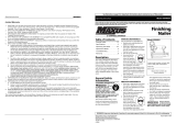
Description
This nailer is designed for trimwork, interior molding, baseboards, paneling and
cabinet assembly and installation. Features include: convenient side loading maga-
zine which holds up to 100 nails, no-mar tip, adjustable exhaust, single cycle trig-
ger and quick clear nose.
Warning indicates
a potentially haz-
ardous situation which, if not avoided,
COULD result in death or serious
injury.
● Disconnect the
nailer from air
supply before
adjusting, clear-
ing jams, servic-
ing, relocating
and during non-
operation. Remember it is possible
for the nailer to eject a fastener
after servicing the tool. ALWAYS
reconnect the air lines before load-
ing any fasteners. Death or serious
personal injury could result.
● Protect your eyes and
ears. Wear Z87 safety
glasses, with side
shields. Wear hearing
protection. Employers
and users are respon-
sible for ensuring the
user or anyone near
the nailer wears this
safety protection.
Serious eye injury or
permanent hearing
loss could result.
● Do not use a
check valve or
any other fit-
ting which
allows air to
remain in the
nailer. Serious
personal injury
could occur.
MANUAL
CAMPBELL
HAUSFELD
Model NB0050
CAMPBELL
PROFESSIONAL
HAUSFELD
110 PSI
O
CO
2
Campbell Hausfeld Nailers meet or exceed Industries’ Standards as set forth by the American
National Standard/International Staple, Nail and Tool Association in ANSI/ISANTA SNT-101-1993.
© 1996 Campbell Hausfeld

Model NB0050
2
Operating Instructions
Warning Continued
● Never place
your hand or
any part of
your body in
the nail dis-
charge area of
the nailer. It is
possible for the
nailer to eject a fastener and could
result in death or serious personal
injury.
● Never carry the
nailer by the air
hose or pull the
hose to move
the nailer or a
compressor.
Keep hoses
away from heat, oil and sharp
edges. Replace any hose that is dam-
aged, weak or worn. Personal injury
or tool damage could occur.
● Always assume the nailer contains
nails. Never use the nailer as a toy.
Do not engage in horseplay. Always
keep others at a safe distance from
the work area in case of accidental
discharge of nails. Never point the
nailer at anyone. Accidental trigger-
ing of the nailer could result in
death or serious personal injury.
● Do not drive a
nail on top of
other nails. The
nail could
glance and
cause death or
a serious punc-
ture wound.
● Do not operate
or allow anyone
else to operate
the nailer if any
warnings or
warning labels
are not legible.
Warnings or
warning labels are located on the
nailer magazine and body.
● Never leave the nailer unattended or
connected to an air compressor when
not in use. Serious personal injury
can occur if someone picks up and
uses the nailer without knowing the
correct way to operate the nailer.
● Do not drop or throw the tool.
Dropping or throwing the tool can
result in damage that will make the
tool unusable or unsafe. If the tool
has been dropped or thrown, exam-
ine the tool closely for bent, cracked
or broken parts and air leaks. STOP
and repair before using or serious
injury could occur.
Caution indicates a
potentially haz-
ardous situation which, if not avoided,
MAY result in minor or moderate injury.
● Do not modify or alter the nailer or
any nailer parts. Do not use the nailer
if any shields or guards are removed
or altered. Do not use the nailer as a
hammer. Serious personal injury may
occur.
● Avoid long extended periods of
work with the nailer. The nailer can
harm the user’s hands or arm. Stop
using the nailer if pain occurs.
● Always check
the work con-
tact element
(WCE) trip
mechanism of
the nailer. A
nail could acci-
dentally be dri-
ven if the trig-
gering mechanism is not working
properly. Serious personal injury
may occur.
● Disconnect air supply and release
tension from the pusher before
attempting to clear jams because
fasteners can be ejected from the
front of the nailer. Personal injury
may occur.
Notice indicates
important informa-
tion, that if not followed, may cause
damage to equipment.
● Avoid using the nailer when there
are no nails in the magazine.
Accelerated wear on the nailer may
occur.
● Clean and check all air supply hoses
and fittings before connecting the
nailer to compressor. Replace any
damaged or worn hoses or fittings.
Tool performance or durability may
be reduced.
● Air compressors providing air to the
nailer should follow the require-
ments established by the American
National Standards Institute
Standard B19.3-1991; Safety
Standard for Compressors for
Process Industries. Contact your air
compressor manufacturer for infor-
mation.
!
NOTICE
Table Of Contents
General Safety . . . . . . . . . . . . . . . .1
Specifications . . . . . . . . . . . . . . . .2
Using The Nailer . . . . . . . . . . . . . .3
Operational Modes . . . . . . . . . . . .3
Operating The Nailer . . . . . . . . . .4
Troubleshooting . . . . . . . . . . . . . .6
Warranty . . . . . . . . . . . . . . . . . . . .7
!
WARNING
Quick Clear Latch
Rubber
No-Mar Tip
Nail Discharge Area
Pin (Single Cycle)
Trigger
Nail Loading Area
Magazine
Nail Pusher
Release Catch
Adjustable Direction
Exhaust Deflector
• REQUIRES: 1.5 SCFM with 10 nails
per minute @ 90 PSI
• AIR INLET: 1/4” NPT
• NAIL SIZE RANGE: 3/4” to 2”
• MAGAZINE CAPACITY:
100 Nails per load, 16 gauge
• WEIGHT: 4 lbs., 13 oz.
• LENGTH: 11-1/2”
• HEIGHT: 11-1/2”
• MAXIMUM PRESSURE: 110 PSI
• PRESSURE RANGE: 70 - 110 PSI
Nailer Components And Specifications
Work Contact
Element (WCE)
Warning Labels

Model NB0050
SINGLE CYCLE MODE
This method is rec-
ommended when
precise nail place-
ment is required.
The single cycle pin
must be installed
in the nailer. This mode requires the
trigger to be pulled each time a nail is
driven. The nailer can be actuated by
depressing the WCE against the work
surface followed by pulling the trigger.
Or the nailer can be actuated by pulling
the trigger and then depressing the
WCE against the work surface.
The trigger must be released to reset
the tool before another nail can be dri-
ven.
If the tool is in bottom trip mode
because the single cycle pin has previ-
ously been removed, reinstall the single
cycle pin to convert the tool back to sin-
gle cycle mode.
BOTTOM TRIP MODE
This method is recommended when less
precise nail place-
ment is required.
The single cycle pin
must be removed
from the nailer.
Remove the pin by
removing the o-
ring on one end and pushing the pin
out. Replace the o-rings on the pin
after removing the pin from the nailer
and keep the pin assembly for later use.
Bottom trip opera-
tion requires the
trigger to be
pulled with the
nailer off the work
surface. Then, the
nose of the nailer is tapped against the
work surface causing a nail to be dri-
ven.
3
Operating Instructions
Using The Nailer
Read this manual and understand
all safety warnings and instruc-
tions before operating the nailer.
LUBRICATION
This nailer requires lubrication before
using the nailer for the first time and
before each use. If an inline oiler is
used, manual lubrication through the
air inlet is not required on a daily basis.
The work surface
can become dam-
aged by excessive lubrication. Proper
lubrication is the owner’s responsibil-
ity. Failure to lubricate the nailer prop-
erly will dramatically shorten the life
of the nailer and void your warranty.
1. Disconnect the
air supply from
the nailer to
add lubricant.
2. Turn the nailer
so the air inlet
is facing up and
put 4-to-5
drops of 30 W
non-detergent
oil into air inlet. Do not use deter-
gent oil or oil additives. Run the nail-
er briefly after adding oil and wipe
off excessive oil at the exhaust.
RECOMMENDED HOOKUP
The illustration below shows the
recommended hookup for the nailer.
1. The air com-
pressor must
be able to
maintain a
minimum of 70
PSI when the
nailer is being
used. An inadequate air supply can
cause a loss of power and inconsis-
tent driving.
!
NOTICE
2. An oiler can be
used to provide
oil circulation
through the
nailer. A filter
can be used to
remove liquid
and solid impurities which can rust
or “gum up” internal parts of the
nailer.
3. Use 3/8” air hoses with a minimum
working pressure of 150 PSI. Use
1/2” air hoses for 50’ run or longer.
For better performance, install a
3/8” quick plug with (1/4” NPT
threads) with an inside diameter of
.315 (8mm) on the nailer and a 3/8”
quick coupler on the air hose.
4. Use a pressure regulator on the
compressor, with an operating pres-
sure of 0 - 125 PSI. A pressure regu-
lator is required to control the oper-
ating pressure of the nailer.
Operational Modes
The NB0050 finish nailer may be oper-
ated in the “Single Cycle” or the
“Bottom Trip” mode. The nailer comes
delivered in the
single cycle mode.
A pin when in
place in the nailer
allows you to
operate in the sin-
gle cycle mode.
When the pin is removed, the nailer
will operate in the bottom trip mode.
Always know the
operational mode
of the nailer before using. Failure to
know the operational mode could
result in death or serious personal
injury.
70 PSI
Min.
Quick Plug
(Optional)
Quick
Coupler
Quick
Coupler
(Optional)
Oiler
Air
Hose
Regulator
Filter
Quick
Plug
Recommended Hookup
Single Cycle Pin
OIL
Pin Out
110 PSI
Max.

Model NB0050
4
Operating Instructions
Each time the
Work Contact
Element (WCE) is
depressed, a nail is
driven into the
work surface. Care
should be taken
when using this method because a nail
will be driven when the WCE is
depressed by any surface.
To convert the tool back to single cycle
operation, reinstall the single cycle pin
and attach an o-ring to each end.
Operating The Nailer
Disconnect the
nailer from the air
compressor before adjusting, clearing
jams, servicing, relocating, and during
non-operation.
WORK CONTACT ELEMENT (WCE)
Check the opera-
tion of the Work
Contact Element (WCE) trip mechanism
before each use. The WCE must move
freely without binding through its
entire travel distance. The WCE spring
must return the WCE to its fully extend-
ed position after being depressed. Do
not operate the nailer if the WCE trip
mechanism is not operating properly.
Personal injury may occur.
1. Disconnect the
air supply from
the nailer.
2. Remove all
nails from the
magazine (See
Loading-
Unloading)
3. Make sure the
trigger and
work contact
element (WCE)
move freely up
and down
without stick-
ing or binding.
4. Reconnect air
supply to the
nailer.
5. Depress the
work contact
element (WCE)
against the
work surface
without pulling
the trigger. The nailer MUST NOT
cycle. Do not use the nailer if it
cycles. Personal injury could result.
6. Hold the nailer
clear of the
work surface.
The work con-
tact element
(WCE) should
return to its original down position.
Pull the trigger. The nailer MUST
NOT cycle. Do not use the nailer if a
cycle occurs. Personal injury could
result.
7. Pull the trigger
and depress the
work contact
element (WCE)
against the
work surface.
The nailer MUST cycle.
8. Depress the
work contact
element (WCE)
against the
work surface.
Pull the trigger.
The nailer MUST cycle.
LOADING/UNLOADING THE NAILER
1. Always connect the tool to the air
supply before loading fasteners.
2. Press down on
the latch. Pull
back on the
magazine
cover.
3. Insert a stick of
Campbell
Hausfeld nails
or equivalent
(See Fastener
Section)into the
magazine. Make sure the pointed
ends of the nails are resting on the
bottom ledge of the magazine
when loading. Make sure the nails
are not dirty or damaged.
4. Push the maga-
zine cover for-
ward until the
latch
catches.
5. Unloading is the reverse of load-
ing, except always disconnect the
air hose before proceeding.
ADJUSTING THE NAIL PENETRATION
1. Regulate the air pressure to 70 PSI
at the nailer.
2. Connect the air
hoses and test
for penetration
by driving nails
into a sample
piece of wood.
If the nails do
not achieve the desired penetra-
tion, adjust the air pressure to a
higher setting until the desired pen-
etration is achieved. Do not exceed
110 PSI at the nailer or durability of
the nailer will be reduced.
ADJUSTING THE DIRECTION OF THE
EXHAUST
The NB0050 is
equipped with an
adjustable direc-
tion exhaust
deflector. This is
intended to allow
the user to change
the direction of the exhaust. Simply
twist the deflector to any direction
desired.
CLEARING A JAM FROM THE NAILER
1. Disconnect the
air supply from
the nailer.
2. Remove all
nails from the
magazine.
Failure to do so
will cause the
nails to eject
from the front
when the quick clear mechanism is
opened and the jam is removed.
3. Undo latch by
pulling out and
down. The wire
latch will disen-
gage from the
hooks on the
nose casting.
Movement
1
1 2
1 2
Rotate
CAMPBELLCAMPBELL
PROFESSIONALPROFESSIONAL
HAUSFELDHAUSFELD

Technical Support
Should you have any questions regard-
ing the operation or repair of this nail-
er, please call our Nailer Hotline at
1-800-543-6400 for assistance. If you
are calling from Ohio or outside of the
continental United States, please call
collect, 1-513-367-1182.
Record the model number and
serial number below:
Model No___________________________
Serial Number_______________________
Retain these number for future
reference.
Fastener And Replacement
Parts
Use only
genuine Campbell
Hausfeld fasteners (or equivalent) and
replacement parts. Do not use modi-
fied parts or parts which will not give
equivalent performance to the original
equipment. Tool performance, safety
and durability could be reduced. When
ordering replacement parts or fasten-
ers, specify by part number.
Model NB0050
5
Operating Instructions
4. The driver
cover plate can
now be rotat-
ed, exposing
the jammed
fastener.
5. Remove the
jammed fas-
tener, using
pliers or a
screwdriver if
required.
6 Rotate driver
cover back into
the closed posi-
tion.
7. Extend the
wire latch and
place over the
hooks on the
nose casting.
8. Close the over
center latch by
pushing the
latch in until
the latch snaps
into place.
Fasteners
The following Campbell Hausfeld finishing nails are available at local retail stores. If you need help locating
any item, call customer service at 1-800-543-6400. Campbell Hausfeld nails meet or exceed Federal
Specifications FF-N-105B.
Shank Nails Per Nails Per
Model # Length
Gauge
Finish Head Collation
Stick Box
FB003060 1-1/4” 16 Gauge Galvanized Brad Adhesive 50 2500
FB004060 1-1/2” 16 Gauge Galvanized Brad Adhesive 50 2500
FB004560 1-3/4” 16 Gauge Galvanized Brad Adhesive 50 2500
FB005060 2” 16 Gauge Galvanized Brad Adhesive 50 2500
Interchange Information
Nails used in the Campbell Hausfeld NB0050 Finishing Nailer will also work in Hitachi NT65A, Paslode 3250-F16, IM250F,
Duo Fast LFN-764, Sears 18314, Porter Cable FN200 and FN250.
COLORMATCH™ System
The Campbell Hausfeld Finishing Nailer
has a unique COLORMATCH™ stripe.
Look for the COLORMATCH™ stripe to
choose the right Campbell Hausfeld
fasteners for your NB0050 2” finish
nailer.
Nailer Repair
Nailer repairs must be performed by
qualified and experienced service peo-
ple ONLY.
Assembly Procedure For
Seals
When repairing a nailer, the internal
parts must be cleaned and lubricated.
Parker O-lube or equivalent must be
used on all o-rings. Each o-ring must be
coated with O-lube before assembling.
A small amount of oil must be used on
all moving surfaces and pivots. After
reassembling, a few drops of 30W non-
detergent oil or equivalent, must be
added through the air line before test-
ing.

Model NB0050
Operating Instructions
6
Air leaking at trigger valve
Air leaking between hous-
ing and nose
Air leaking between hous-
ing and cap
Nailer skips driving nail
Nailer runs slow or has loss
of power
Nails are jammed in nailer
Air leaking at trigger valve
stem
O-Rings in trigger valve housing are
damaged
Loose screws in housing
Damaged O-Rings
Damage to bumper
Loose screws
Damaged gasket
Worn bumper
Dirt in nose piece
Dirt or damage prevent nails or pusher
from moving freely in magazine
Damaged pusher spring
Inadequate air flow to nailer
Worn O-Ring on piston or lack of
lubrication
Damaged O-Ring on trigger valve
Air leaks
Cap gasket leaking
Nailer not lubricated sufficiently
Broken spring in cylinder cap
Exhaust port in cap is blocked
Guide on driver is worn
Nails are not correct size
Nails are bent
Magazine or nose screws are loose
Driver is damaged
O-Rings or seals are damaged
O-Rings must be replaced & operation of work
contact element must be checked
Screws need to be tightened
O-Rings must be replaced
Bumper needs to be replaced
Screws need to be tightened
Gasket needs to be replaced
Bumper needs to be replaced
Drive channel needs to be cleaned
Magazine needs to be cleaned
Spring needs to be replaced
Fitting, hose or compressor needs to be checked
O-Rings need to be replaced. Lubricate.
O-Rings need to be replaced
Screws and fittings need to be tightened
Gasket needs to be replaced
Nailer needs to be lubricated
Spring needs to be replaced
Damaged internal parts need to be replaced
Guide needs to be replaced
Nails recommended for nailer must be use
Replace with undamaged nails
Screws need to be tightened
Driver needs to be replaced
O-Rings or seals need to be replaced
Troubleshooting Guide
Stop using nailer immediately if any of the following problems occur. Serious
personal injury could result. Any repairs or replacements must be done by a
Qualified Service Person or Authorized Service Center.
Problem Cause Solution

Model NB0050
7
Operating Instructions
Limited Warranty
1. DURATION: One year from the date of purchase by the original purchaser.
2. WHO GIVES THIS WARRANTY (WARRANTOR):
The Campbell Group
A Scott Fetzer Company
100 Production Drive
Harrison, Ohio, 45030
Telephone: 1-800-543-6400.
3. WHO RECEIVES THIS WARRANTY (PURCHASER): The original purchaser (other than for purposes of resale) of the
Campbell Hausfeld product.
4. WHAT PRODUCTS ARE COVERED BY THIS WARRANTY: Any Campbell Hausfeld nailer.
5. WHAT IS COVERED UNDER THIS WARRANTY: Defects on material and workmanship which occur within the duration of
the warranty period.
6. WHAT IS NOT COVERED UNDER THIS WARRANTY:
A. Implied warranties, including those of merchantability and FITNESS FOR A PARTICULAR PURPOSE ARE LIMITED TO ONE
YEAR FROM THE DATE OF ORIGINAL PURCHASE. Some states do not allow limitations on how long an implied warranty
lasts, so the above limitations may not apply to you.
B. ANY INCIDENTAL, INDIRECT, OR CONSEQUENTIAL LOSS, DAMAGE, OR EXPENSE THAT MAY RESULT FROM ANY DEFECT,
FAILURE, OR MALFUNCTION OF THE CAMPBELL HAUSFELD PRODUCT. Some states do not allow the exclusion or limita-
tion of incidental or consequential damages, so the above limitation or exclusion may not apply to you.
C. Any failure that results from an accident, purchaser’s abuse, neglect or failure to operate products in accordance with
instructions provided in the owner’s manual(s) supplied with product. Accident, purchaser’s abuse, neglect or failure to
operate products in accordance with instructions shall also include the removal or alteration of any safety devices. If
such safety devices are removed or altered, this warranty is void.
D. Normal adjustments which are explained in the owner’s manual(s) provided with the product.
E. Items or service that are normally required to maintain the product, i.e. o-rings, springs, bumpers, debris shield, driver,
etc. These said normal wear items will be covered only for ninety days from the date of original purchase.
7. RESPONSIBILITIES OF WARRANTOR UNDER THIS WARRANTY: Repair or replace, at Warrantor’s option, products or com-
ponents which have failed within duration of the warranty period.
8. RESPONSIBILITIES OF PURCHASER UNDER THIS WARRANTY: A. Deliver or ship the Campbell Hausfeld product or compo-
nent to the nearest Campbell Hausfeld Authorized Service Center. Freight costs, if any, must be borne by the purchaser.
B. Use reasonable care in the operation and maintenance of the products as described in the owner’s manual(s).
9. WHEN WARRANTOR WILL PERFORM REPAIR OR REPLACEMENT UNDER THIS WARRANTY:
A. Repair or replacement will be scheduled and serviced according to the normal work flow at the servicing location, and
depending on the availability of replacement parts.
B. If the purchaser does not receive satisfactory results from the Authorized Service Center, the purchaser should contact
the Campbell Hausfeld Product Service Department (see paragraph 2).
This Limited Warranty gives you specific legal rights and you may also have other rights which vary from state to state.
Printed In Taiwan

Operating Instructions
NB0050
Notes
8
/