Campbell Hausfeld RN1545 User manual
- Category
- Nail Gun
- Type
- User manual
This manual is also suitable for

Coil Roofing
Nailer
EMPLOYER’S RESPONSIBILITY:
Distribute this instruction manual to all
users before allowing use of the nailer.
Ensure all operators read, understand
and follow all safety warnings, labels
and instructions outlined in this manual.
Danger
indicates
an imminently hazardous situation
which, if not avoided, will result in
death or serious injury.
Do not use any type of
flammable gases or
oxygen as a power
source for the nailer.
Use filtered, lubricated,
regulated compressed air only. Use
of a compressed gas instead of
compressed air may cause the nailer
to explode which will cause death
or serious personal injury.
Do not exceed maxi-
mum operating pressure
of the nailer (120 psi).
The nailer will not func-
tion properly. Do not
use a compressed air
source capable of more than 200 PSI.
The nailer could explode which will
cause death or serious personal injury.
Never use gasoline or
other flammable liquids
to clean the nailer.
Never use the nailer in
the presence of flam-
mable liquids or gases. Vapors could
ignite by a spark and cause an
explosion which will result in death
or serious personal injury.
Always remain in a
firmly balanced posi-
tion when using or
handling the nailer.
Do not modify or
disable the Work
Contact Element
(WCE). Do not tie or
tape the WCE or
trigger in a
depressed position.
Death or serious personal injury
could result.
Description
This nailer is designed for roofing
(asphalt and fiberglass shingles), reroof-
ing, and sheathing installation. Features
include: convenient top loading maga-
zine which holds up to 120 nails, an
adjustable shingle guide, a rubber han-
dle grip, an adjustable depth of drive
mechanism and adjustable exhaust.
General Safety Information
This manual contains safety, operational
and maintenance information.
Read this manual and under-
stand all safety warnings and
instructions before operating
the nailer. Contact your
Campbell Hausfeld represen-
tative if you have any questions.
CALIFORNIA PROPOSITION 65
You can create dust when you
cut, sand, drill or grind materi-
als such as wood, paint,
metal, concrete, cement, or other mason-
ry. This dust often contains chemicals
known to cause cancer, birth defects, or
other reproductive harm. Wear protec-
tive gear.
Excessive
exposure to vibration, working in awk-
ward positions and repetitive work
motions can cause injury to hands and
arms. Stop using any tool if discomfort,
numbness, tingling or pain occur and
consult a physician.
OPERATOR’S RESPONSIBILITY:
Before operating the nailer, read and
understand all safety warnings and
labels. Follow the operating instruc-
tions outlined in this manual.
Operating Instructions Model RN164500
Do not touch the trig-
ger unless driving nails.
Never attach air line to
nailer or carry nailer
while touching the
trigger. The tool could
eject a fastener which will result in
death or serious personal injury.
Warning
indicates
a potentially hazardous situation
which, if not avoided, COULD result in
death or serious injury.
Always discon-
nect nailer from
air line before
clearing jams,
adjusting or ser-
vicing the nailer, relocating the
nailer, or when the nailer is not in
use. Always reconnect the air line
BEFORE loading any fasteners. The
nailer could eject a fastener causing
death or serious personal injury.
Protect your eyes and
ears. Wear Z87 safety
glasses, with side
shields. Wear hearing
BUILT TO LAST
Please read and save these instructions. Read carefully before attempting to assemble, install, operate or maintain the product described.
Protect yourself and others by observing all safety information. Failure to comply with instructions could result in personal injury, death
and/or property damage! Retain instructions for future reference.
Model RN164500
IN718600AV 3/07
Campbell Hausfeld Nailers meet or exceed Industries’ Standards as set forth by the American National
Standard Institute/International Staple, Nail and Tool Association in ANSI/ISANTA SNT-101-2007.
© 2007 Campbell Hausfeld
Table Of Contents
General Safety . . . . . . . . . . . . . . . . .1-2
Specifications . . . . . . . . . . . . . . . . . . . .2
Contact Trip Safety Mechanism . . . . .3
Operating The Nailer . . . . . . . . . . . .3-5
Troubleshooting . . . . . . . . . . . . . . . . .6
Warranty . . . . . . . . . . . . . . . . . . . . . . .7
8-Sp
Modelo RN164500
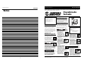
Notas
Manual de Instrucciones
Locate model and serial number on
tool and record below:
Model No. ________________________
Serial No. _________________________
Retain these numbers for
future reference.
MANUAL
O
CO
2
120 psi
MAX.

2
protection. Employers and users
are responsible for ensuring the
user or anyone near the nailer
wears this safety protection.
Serious eye injury or permanent
hearing loss could result.
Do not use a check
valve or any other
fitting which
allows air to
remain in the nail-
er. Death or serious
personal injury could occur.
Never place hands or
any other body parts in
the nail discharge area
of the nailer. The nailer
might eject a fastener
and could result in
death or serious per-
sonal injury.
Never carry the nailer
by the air hose or pull
the hose to move the
nailer or a compressor.
Keep hoses away from
heat, oil and sharp
edges. Replace any hose that is
damaged, weak or worn. Personal
injury or tool damage could occur.
Always assume the nailer contains
nails. Never use the nailer as a toy.
Do not engage in horseplay. Always
keep others at a safe distance from
the work area in case of accidental
discharge of nails. Never point the
nailer at anyone. Accidental trigger-
ing of the nailer could result in
death or serious personal injury.
Do not drive a nail
on top of other
nails. The nail could
glance and cause
death or a serious
puncture wound.
Do not operate
or allow anyone
else to operate
the nailer if any
warnings or
warning labels
are not legible. Warnings or warning
labels are located on the nailer maga-
zine and body.
Never leave the nailer unattended or
connected to an air compressor when
not in use. Serious personal injury
can occur if someone picks up and
uses the nailer without knowing the
correct way to operate the nailer.
Do not drop or throw the tool.
Dropping or throwing the tool can
result in damage that will make the
tool unusable or unsafe. If the tool
has been dropped or thrown, exam-
ine the tool closely for bent, cracked
or broken parts and air leaks. STOP
and repair before using or serious
injury could occur.
Caution
indicates a
potentially hazardous situation which, if
not avoided, MAY result in minor or
moderate injury.
Do not modify or alter the nailer or
any nailer parts. Do not use the nailer
if any shields or guards are removed
or altered. Do not use the nailer as a
hammer. Personal injury or tool dam-
age may occur.
Avoid long extended periods of work
with the nailer. Stop using the nailer
if you feel pain in hands or arms.
Always check that the
Work Contact Element
(WCE) is operating
properly. A nail could
accidentally be driven
if the WCE is not
working properly. Personal injury
may occur (See "Checking the Work
Contact Element" Section).
Disconnect air supply and release
tension from the pusher before
attempting to clear jams because
fasteners can be ejected from the
front of the nailer. Personal injury
may occur.
Notice
indicates
important information, that if not fol-
lowed, may cause damage to equipment.
Avoid using the nailer when the
magazine is empty. Accelerated
wear on the nailer may occur.
Clean and check all air supply hoses
and fittings before connecting the
nailer to an air supply. Replace any
damaged or worn hoses or fittings.
Tool performance or durability may
be reduced.
Air compressors providing air to the
nailer should follow the require-
ments established by the American
National Standards Institute
Standard B19.3-1991; Safety
Standard for Compressors for Process
Industries. Contact your air compres-
sor manufacturer for information.
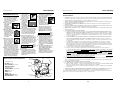
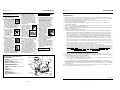
Model RN164500
Operating Instructions
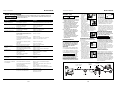
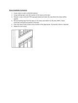
Nail
Discharge
Area
Magazine
Cover
Magazine
Trigger
Air Inlet
Shingle
Guide
Door Latch
• REQUIRES: 4.5 SCFM with 25 nails
per minute @ 90 psi
• AIR INLET: 1/4” NPT
• NAIL SIZE RANGE: 7/8” to1-3/4”
• MAGAZINE CAPACITY:
120 Nails per load
• SHANK DIAMETER: .120" Diameter
• WEIGHT: 5 lbs., 8 oz.
• LENGTH: 10 1/8”
• HEIGHT: 11 1/2”
• MAXIMUM PRESSURE: 120 psi
• PRESSURE RANGE: 70 - 120 psi
Nailer Components And Specifications
7-Sp
Manual de Instrucciones
Modelo RN164500
Work Contact
Element
Impreso en China
!
WARNING
Garantía Limitada
1. DURACIÓN: Desde la fecha de compra por parte del comprador original, según se detalla: Campbell Hausfeld (Trabajo
estándar y sin especificar) – 1 (un) año, (Trabajo pesado) – 2 (dos) años, (Trabajo extremo) – 3 (tres) años; IronForce de
Campbell Hausfeld – 1 (un) año; Farmhand – 3 (tres) años; Maxus – 5 (cinco) años.
2. QUIEN OTORGA ESTA GARANTIA (EL GARANTE: Campbell Hausfeld / The Scott Fetzer Company 100 Production Drive,
Harrison, Ohio 45030 Teléfono: (800) 543-6400
3. QUIEN RECIBE ESTA GARANTIA (EL COMPRADOR): El comprador original (que no sea un revendedor) del producto
Campbell Hausfeld.
4. PRODUCTOS CUBIERTOS POR ESTA GARANTIA: Cualquier clavadora, grapadora, herramienta neumática, pistola pulver-
izadora, inflador o accesorio neumático suministrado o fabricado por el Garante.
5. COBERTURA DE LA GARANTIA: Los defectos substanciales de material y fabricación que ocurran dentro del período de
validez de la garantía.
6. LO QUE NO ESTA CUBIERTO POR ESTA GARANTIA:
A. Las garantías implícitas, incluyendo aquellas de comercialidad E IDONEIDAD PARA FINES PARTICULARES, ESTAN
LIMITADOS A LO ESPECIFICADO EN EL PARRAFO DE DURACION. Si este producto es empleado para uso comercial,
industrial o para renta, la garantía será aplicable por noventa (90) días a partir de la fecha de compra. En algunos
estados no se permiten limitaciones a la duración de las garantías implícitas, por lo tanto, en tales casos esta lim-
itación no es aplicable.
B. CUALQUIER PERDIDA DAÑO INCIDENTAL, INDIRECTO O CONSECUENTE QUE PUEDA RESULTAR DE UN DEFECTO,
FALLA O MALFUNCIONAMIENTO DEL PRODUCTO CAMPBELL HAUSFELD. En algunos estados no se permite la
exclusión o limitación de daños incidentales o consecuentes, por lo tanto, en tales casos esta limitación o exclusión
no es aplicable
C. Cualquier falla que resulte de un accidente, abuso, negligencia o incumplimiento de las instrucciones de fun-
cionamiento y uso indicadas en el (los) manual(es) que se adjunta(n) al producto. Dichos accidentes, abusos por
parte del comprador, o falta de operar el producto siguiendo las instrucciones del manual de instrucciones sumin-
istrado también debe incluir la desconexión o modificación de los instrumentos de seguridad. Si dichos instrumen-
tos de seguridad son desconectados, la garantía quedaría cancelada.
D. Los ajustes normales explicados en el(los) manual(es) suministrado(s) con el producto.
E. Artículos o servicios normalmente requeridos para el mantenimiento del producto, tales como: anillos en O,
resortes, amortiguadores, defensas, hojas de impulsor, fusibles, baterías
, empaques, almohadillas o sellos, boquillas
de fluído, agujas, boquillas para rociar arena, lubricantes
, mangueras de material, elementos filtrantes, álabes de
motores, abrasivos, hojillas, discos para cortar, cinceles, retenes para cinceles, cortadores, collarines, mandriles, mor-
dazas para remachadoras, brocas para desarmadores, almohadillas para lijar
, soportes de almohadillas, mecanismo
de impacto o cualquier otro artículo desgastable que no se haya enumerado específicamente. Estos artículos sólo
estarán cubiertos bajo esta garantía por noventa (90) días a partir de la fecha de compra original. Los artículos sub
-
rayados sólo están garantizados por defectos de material o fabricación.
F. Defectos estéticos que no interfieran con la función del producto
7. RESPONSABILIDADES DEL GARANTE BAJO ESTA GARANTIA: Reparar o reemplazar, como lo decida el Garante, los pro-
ductos o componentes que estén defectuosos, se hayan dañado o hayan dejado de funcionar adecuadamente, durante
el período de validez de la garantía
8. RESPONSABILIDADES DEL COMPRADOR BAJO ESTA GARANTIA:
A. Suministrar prueba fechada de compra y la historia de mantenimiento del producto.
B. Entregar o enviar el producto o componente Campbell Hausfeld al Centro de Servicio autorizado Campbell Hausfeld
más cercano. Los gastos de flete, de haberlos, deben ser pagados por el comprador.
C. Seguir las instrucciones sobre operación y mantenimiento del producto, tal como se indica(n) en el (los) manual(es)
del propietario
9. CUANDO EFECTUARA EL GARANTE LA REPARACION O REEMPLAZO CUBIERTO BAJO ESTA GARANTIA: La reparación o
reemplazo dependerá del flujo normal de trabajo del centro de servicio y de la disponibilidad de repuestos.
Esta garantía limitada es válida sólo en los EE.UU., Canadá y México y otorga derechos legales específicos. Usted también
puede tener otros derechos que varían de un Estado a otro. o de un país a otro.
General Safety
Information (Continued)
Adjustable
exhaust
Adjustable
depth control

3
Operation
Read this manual and understand all
safety warnings and instructions before
operating the nailer.
LUBRICATION
This nailer requires lubrication before
using the nailer for the first time and
before each use. If an inline oiler is
used, manual lubrication through the
air inlet is not required on a daily basis.
The work
surface
can become damaged by excessive
lubrication. Proper lubrication is the
owner’s responsibil- ity. Failure to
lubricate the nailer properly will dra-
matically shorten the life of the nailer
and void your warranty.
1. Disconnect
the air supply
from the nail-
er to add
lubricant.
2. Turn the nailer
so the air inlet
is facing up.
Place 4-5 drops
of 30 W non-
detergent oil into air inlet. Do not
use detergent oils, oil additives, or
air tool oils. Air tool oils contain sol-
vents which will damage the nailer's
internal components.
3. After adding oil,
run nailer briefly.
Wipe off any
excess oil from
the cap exhaust.
Always
know the
operational mode of the nailer before
using. Failure to know the operational
mode could result in death or serious
personal injury.
This nailer may be operated in the
“Single Cycle” or the “Bottom Trip”
mode. The nailer is delivered in the sin-
gle cycle mode. A separate ‘red’ trigger
for “Bottom Trip” mode is included
with tool as an accessory.
SINGLE CYCLE MODE
When the black trigger is installed, nail-
er is in single cycle mode. This method
is recommended when precise nail
placement is required. Operation in this
mode requires trigger to be pulled each
time a nail is driven. Nailer can be actu-
ated by depressing the Work Contact
Element (WCE) against work surface
followed by pulling the trigger.
The trigger must be released after each
fastener is driven to allow tool to reset.
Since the tool can only be actuated by
first removing the finger from the trig-
ger, this is considered to be a more
restrictive mode of operation, suitable
for less experienced users.
BOTTOM TRIP MODE
When the red trigger is installed, the
nailer is in bottom trip mode. This
method is recommended when less
precise nail placement is required.
Operation in this mode requires trigger
to be depressed with nailer off of the
work surface. Then, the nose of the
nailer is tapped against the work sur-
face causing a nail to be driven.
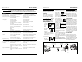
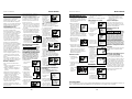
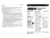
RECOMMENDED HOOKUP
The illustration below shows the
recommended hookup for the nailer.
1. The air compressor
must be able to
maintain a mini-
mum of 70 PSI
when the nailer is
being used. An inadequate air sup-
ply can cause a loss of power and
inconsistent driving.
2. An oiler can be used to
provide oil circulation
through the nailer. A fil-
ter can be used to remove
liquid and solid impurities
which can rust or “gum up” internal
parts of the nailer.
3. Use 3/8” air
hoses with a
minimum work-
ing pressure of
200 psi. Use 1/2” air hoses for 50’
run or longer. For better perfor-
mance, install a 3/8” quick plug
(1/4” NPT threads) with an inside
diameter of .315” (8mm) on the
nailer and a 3/8” quick coupler on
the air hose.
4. Use a pressure regulator on the
compressor, with an operating pres-
sure of 0 - 125 PSI. A pressure regu-
lator is required to control the oper-
ating pressure of the nailer between
70 and 120 psi.
Operational Modes
Note: This framing nailer is shipped
with the BLACK single cycle mode trig-
ger installed.
Model RN164500
Operating Instructions
70 PSI
Min.
OIL DAILY
Oxygen
Oxygen
Nitrogen
Nitrogen
Hydrogen
Hydrogen
Carbon Dioxide
Carbon Dioxide
OIL DAILY
O
xy
ge
n
N
itr
oge
n
Hyd
r
o
ge
n
Ca
r
b
o
n
Dio
x
ide
OIL
120 PSI
Max.
OIL DAILY
Oxygen
O
xygen
Nitrogen
Nitrogen
Hydrogen
Hydrogen
Carbon Dioxide
Carbon Diox
ide
Hay una fuga de aire en el
área de la válvula del gatillo
Hay una fuga de aire entre la
cubierta y la boquilla
Hay una fuga de aire entre la
cubierta y la tapa
La clavadora deja de clavar un
clavo
La clavadora funciona lenta-
mente o pierde su potencia
Hay clavos atascados en la
clavadora
Hay una fuga de aire en el
vástago de la válvula del gatillo
El clavador omite clavar un
clavo o no alimenta los clavos
adecuadamente
Los clavos están bloqueados en
el cargador
Los anillos en O de la cubierta de la válvula del
gatillo están dañados
Los tornillos de la cubierta están flojos
Los anillos en O están dañados
La defensa está dañada
Los tornillos están flojos
El empaque está dañado
La defensa está desgastada
La boquilla está sucia
La suciedad o daños evitan el desplazamiento
libre de los clavos o el mecanismo de impulso
en el cargador
El resorte del mecanismo de impulso está dañado
El flujo de aire hacia la clavadora es inadecuado
El anillo en O del pistón está desgastado o le
falta lubricación
Los anillos en O de la válvula del gatillo están
dañados
Hay fugas de aire
Hay una fuga en el empaque de la tapa
La clavadora no está bien lubricada
El resorte de la tapa del cilindro está roto
El orificio de salida de la tapa está obstruído
La guía del mecanismo de impulso está desgastada
Los clavos no son del tamaño adecuado.
Los clavos están doblados
Los tornillos del cargador o de la boquilla están flojos
El mecanismo de impulso está dañado
Los anillos en O o los sellos están dañados
CLAVADORES DE BOBINA
Pistón de alimentación de clavos está seco
Juntas tóricas dañadas enel pistón de ali-
mentación de clavos.
Verificar atascamiento del trinquete
Parte inferior del cargardor no está ajustada
correctamente
Alambres soldados en la bobina de clavos están
rotos
Tamaño incorrecto de los clavos
Alambres soldados en la bobina de clavos están
rotos
Debe reemplazar los anillos en O & chequear el fun-
cionamiento del elemento de funcionamiento al contacto
Debe apretar los tornillos
Debe reemplazar los anillos en O
Debe reemplazar la defensa
Debe apretar los tornillos
Debe reemplazar el empaque
Debe reemplazar la defensa
Debe limpiar el canal del sistema de impulso
Debe limpiar el cargador
Debe reemplazar el resorte
Chequée las conexiones, la manguera o el compresor
Debe reemplazar los anillos en O. Lubríquelos.
Debe reemplazar los anillos en O
Debe apretar los tornillos y las conexiones
Debe reemplazar el empaque
Necesita lubricar la clavador
Debe reemplazar el resorte
Debe reemplazar las partes internas dañadas
Debe reemplazar la guía
Debe usar los clavos recomendados para esta clavadora
Reemplácelos con clavos en buenas condiciones
Debe apretar los tornillos
Debe reemplazar el mecanismo de impulse de clavos
Debe reemplazar los anillos en O o los sellos
Lubricar el pistón con lubricante extraligero
Reemplazar las juntas tóricas. Revisar el tope y el resorte.
Lubricar el conjunto
Verificar el trinquete y el resorte de la puerta
La parte inferior del cargador debe ser ajustada de acuer-
do al largo de los clavos usados
No utilice los clavos
Debe usar los clavos recomendados para el clavador
No utilice los clavos
Guía de Diagnóstico de Averías
Deje de usar la clavadora inmediatamente si alguno de los si guientes problemas ocurre.
repuestos. Podría resultado le heridas graves. Cualquier reparación o reemplazo de piezas los
debe hacer un técnico calificado personal de un centro autorizado de servicio.
Problema Causa Solución
6-Sp
Manual de Instrucciones
Modelo RN164500
Recommended Hookup
Quick
Plug
Quick
Coupler
Air
Hose
Quick Plug
(Optional)
Quick
Coupler
(Optional)
Oiler
Regulator
Filter

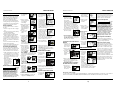
1. Disconnect the
air supply from
the nailer.
2. Remove all nails
from the magazine
(see Loading/
Unloading).
3.
Make sure the trigger
and Work Contact
Element (WCE) move
freely up and down
without sticking or
binding.
4. Reconnect air
supply to the
nailer.
5.
Depress the WCE
against the work
surface without
pulling the trig-
ger. The nailer
MUST NOT
OPERATE. Do not use the tool if it
operates without pulling the trigger.
Personal injury may result.
6. Remove the nailer
from the work sur-
face. The
WCE
must
return to its original
down position.
Depress the trigger.
The nailer MUST
NOT OPERATE. Do not use the tool if
it operates while lifted from the work
surface. Personal injury may result.
7. Pull the trig-
ger and
depress the
WCE
against
the work sur-
face. The nail-
er MUST OPERATE if bump trigger is
installed. The nailer MUST NOT OPER-
ATE if sequential trigger is installed.
8. Depress the
WCE
against
the work sur-
face. Pull the
trigger. The
nailer MUST
OPERATE.
LOADING/UNLOADING THE NAILER
1. Always connect the tool to the air
supply before loading fasteners.
OIL DAILY
Oxygen
Oxygen
Nitrogen
Nitrogen
Hydrogen
Hydrogen
Carbon Dioxide
C
arbon Dioxide
OIL DAILY
Oxygen
Nitrogen
Hydrogen
Carbon Dioxide
Movement
O
I
L
D
A
I
L
Y
O
I
L
D
A
I
L
Y
O
x
y
g
e
n
O
x
y
g
e
n
N
i
t
r
o
g
e
n
N
i
t
r
o
g
e
n
H
y
d
r
o
g
e
n
H
y
d
r
o
g
e
n
C
a
r
b
o
n
D
i
o
x
i
d
e
C
a
r
b
o
n
D
i
o
x
i
d
e
OIL DAILY
Oxygen
Nitrogen
Nitrogen
Hydrogen
Hydrogen
Carbon Dioxide
Carbon Dioxide
Each time the Work Contact Element is
depressed, a nail is driven into the work
surface. Extreme care should be taken
because a nail will be driven when the
WCE is pressed against any surface.
Since the tool can be actuated without
removing the finger from the trigger, this
is considered to be a less restrictive mode,
suitable for more experienced users.
MODE CONVERSION
To convert the tool from one mode to
the other:
1. Remove o-ring on the side of trigger
pin.
2. Remove trigger pin, trigger, and trig-
ger spring (if included).
3. Switch out only the trigger.
4. Replace trigger spring (if included),
trigger, trigger pin, and o-ring.
Do not attempt to modify the trigger
components in any manner and do not
attempt to use any other trigger com-
ponents other than those intended for
this tool.
See the tool manual for further Safety
and Operation information.
Contact your Campbell Hausfeld repre-
sentative if you have any questions.
ADJUSTING NAIL PENETRATION
The tool is equipped with an adjustable
depth of drive feature. This feature allows
the user to determine how deep the fas-
tener will be driven into the work surface.
a. Adjust operating pressure so nails are dri-
ven consistently. Do not exceed 120 psi.
b. Turn thumbwheel to decrease the gap
between tip of WCE and nose to maxi-
mize depth; increase the gap to mini-
mize depth.
c. Make sure trigger
and work contact ele-
ment (WCE) move
freely up and down
without binding or
sticking after each
adjustment.
WORK CONTACT ELEMENT (WCE)
Check the
operation
of the Work Contact Element (WCE) trip
mechanism before each use. The WCE
must move freely without binding
through its entire travel distance. The
WCE spring must return the WCE to its
fully extended position after being
depressed. Do not operate the nailer if
the WCE trip mechanism is not operating
properly. Personal injury may occur.
2. Pull the door latch
down andopen the
door. Open maga-
zine cover.
3. Check the nail plat-
form adjustment.
Change nail plat-
form settings by
turning knob on the
post and twisting to the correct setting:
The nail platform must be set for the
length of nails to be used or the nails
will not feed properly.
4. Load the coil of nails
over the post in the
magazine. Make sure
to uncoil enough
nails to reach the
feed pawl. The first
nail should be placed in front of the
front tooth on the feed pawl in the
driver channel and the nail heads
must be in the slot in the nose.
5. Close the magazine
cover and door latch.
6. Always unload all fasteners before
removing tool from service.
Unloading is the reverse of loading,
except always disconnect the air hose
before unloading.
SHINGLE GUIDE ADJUSTMENT
1. Disconnect the
air supply from
the nailer.
2.
Loosen the two screws on the shingle
guide under the magazine.
3. Place the shingle
guide against the
front edge of the
shingle.
4. Adjust the shingle guide until the
desired shingle exposure is achieved.
5. Tighten the two screws on the shin-
gle guide.
CLEARING A JAM FROM THE NAILER
1. Disconnect the
air supply from
the nailer.
Model RN164500
Operating Instructions
4
OIL DAILY
Oxygen
Oxy
g
en
Nitrogen
N
i
troge
n
Hydrogen
Hydrogen
Carbon Diox
ide
C
ar
bon
Diox
ide
4. Coloque una bobina
de clavos en el car-
gador sobre la barra
del cargador.
Asegúrese de desenr-
rollar suficientes clavos hasta alcan-
zar el trinquete de avance. El primer
clavo debe colocarse delante del
diente delantero en el trinquete de
avance, en el canal del expulsador y
las cabezas de los clavos deben estar
en la ranura de la nariz del clavador.
5. Cierre el retén y la
tapa del cargador.
6.
Para descargarla haga lo contrario
que para cargarla, excepto que siem-
pre debe desconectar la manguera
de aire antes de comenzar.
AJUSTE DE LA GUIA PARA TEJAS DE
MADERA
1. Desconecte la
clavadora de la
fuente de sum-
inistro de aire.
2.
Afloje los dos tornillos de la guía que
se encuentran bajo el cargador.
3. Coloque la
guía contra
el borde
delantero de
la teja.
4. Ajuste la guía de tejas hasta lograr la
exposición deseada para la teja.
5. Apriete los dos tornillos de la guía
para tejas de madera.
QUE HACER CUANDO LA CLAVADO-
RA TENGA UN CLAVO ATASCADO
1. Desconecte la
clavadora de la
fuente de sumin-
istro de aire.
2. Tire el retén de la
portezuela hacia
abajo y abra la
tapa del cargador.
3. Saque los clavos
de la nariz del
clavador.
4. Sujete el clavo
atascado con unas
pinzas y extráiga-
lo del clavador.
Metodo alterno:
1. Inserte un
destornillador
en la nariz del
clavador.
Empuje hacia
arriba la hoja
del expulsador a fin de liberar el
clavo atascado.
2. Sujete el clavo
con unas pin-
zas y sáquelo
del clavador.
Mantenimiento
Limpieza del Clavador
1. Desconectar
el suministro
de aire del
clavador.
2. Limpie las
acumula-
ciones de
alquitrán con
aceite com-
bustible
kerosén #2 o
con combustible diesel. No permita
que el combustible penetre en el
cilindro del expulsador pues se
puede causar daño. Seque completa-
mente el clavador antes de usarlo.
Servicio Técnico
Si desea hacer alguna pregunta refer-
ente a la reparación u operación de las
clavadoras, sírvase llamar a nuestro
número especial, 1-800-543-6400.
Clavos et Repuestos
Use sola
mente
sujetadores Campbell Hausfeld origi-
nales (o su equivalente) - (vea la infor-
mación sobre intercambio de sujeta-
dores). Use solamente partes de
repuesto Campbell Hausfeld originales.
Nunca substituya las partes. No use
partes modificadas o partes que no den
un rendimiento equivalente al equipo
original. El rendimiento de las her-
ramientas, la seguridad y la duración
pueden verse reducidos. Cuando
ordene partes de repuesto o sujeta-
dores, especifique el número de la
parte.
Para reparar la clavadora
Las reparaciones de la clavadora las
debe hacer SOLAMENTE un técnico cal-
ificado que tenga experiencia.
Para colocarle los sellos
Cada vez que repare una clavadora
deberá limpiarle y lubricarle las partes
internas. Le recomendamos que use
Parker O-lube o un lubricante equiva-
lente en todos los anillos en O. A cada
anillo en O se le debe dar un baño de
lubricante para anillos antes de insta-
larlos. Igualmente, deberá ponerle un
poco de aceite a todas las piezas que se
mueven y muñones. Finalmente,
después de haberla ensamblado y antes
de probar la herramienta deberá pon-
erle unas cuantas gotas de aceite sin
detergente 30W u otro aceite similar,
en las líneas de aire.
Modelo RN164500
5-Sp
Manual de Instrucciones
OIL DAILY
Oxygen
Oxygen
Nitrogen
Nitrogen
Hydrogen
Hydrogen
Carbon Dioxide
C
arbo
n
D
io
xi
de
OIL DAILY
Oxygen
Nitrogen
Hydrogen
Carbon Dioxide
OIL DAILY
Oxygen
Oxygen
Nitrogen
Nitrogen
Hydrogen
Hydrogen
Carbon Dioxide
Carbon Dioxide
Oxygen
Nitrogen
Hydrogen
Carbon Dioxide
SHINGLE EXPOSURE
OIL DAILY
Oxygen
Nitrogen
Hydrogen
Carbon Dioxide
Movement
O
I
L
D
A
I
L
Y
O
I
L
D
A
I
L
Y
O
x
y
g
e
n
O
x
y
g
e
n
N
i
t
r
o
g
e
n
N
i
t
r
o
g
e
n
H
y
d
r
o
g
e
n
H
y
d
r
o
g
e
n
C
a
r
b
o
n
D
i
o
x
i
d
e
C
a
r
b
o
n
D
i
o
x
i
d
e
1.
2.
OIL DAILY
Oxyg
en
Oxyg
e
n
Nitr
ogen
Nitro
gen
Hydr
o
gen
Hy
d
r
o
g
en
Carbo
n Dioxi
de
Car
bo
n
Dio
x
id
e
OIL DAILY
Oxyg
en
O
xyg
en
Nitrogen
Nitrogen
Hydrogen
Hy
drogen
Carbon Dioxide
C
arb
on
Di
oxi
de
1.
2.
Información de intercambio
Los clavos usados con la clavadora para acabado RN164500 de Campbell Hausfeld también se pueden usar con las clavadoras
Rollo de techado ATRO, Bostitch RN45, N12B, Hitachi NV45AB, Porter Cable RN175, Sears 18324 y Senco SCN200R.
OIL DAILY
Oxygen
Nitrogen
Nitrogen
Hydrogen
Hydrogen
Carbon Dioxide
Carbon Dioxide
OIL DAILY
Ox
ygen
Oxygen
Nitrogen
Nitrogen
Hydrogen
Hyd
rogen
Ca
rbon Dioxide
Carbon
D
io
xide
Oxygen
Oxygen
Nitrogen
Hydrogen
Hydrogen
Carbon Dioxide
Carbon Dioxide
SHINGLE EXPOSURE
Exposición para la teja
Operation (Continued)
OIL DAILY
Oxygen
Oxy
g
en
Nitrogen
Nit
ro
gen
Hydrogen
H
yd
ro
g
e
n
Carbon
Dioxide
Ca
rbon
Diox
id
e
OIL DAILY
Oxygen
Oxygen
Nitrogen
Nitrogen
Hydrogen
Hydrogen
Carbon Dioxide
Carbon Dioxide
OIL DAILY
Oxygen
Nitrogen
Nitrogen
Hydrogen
Hydrogen
Carbon Dioxide
Carbon Dioxide
Funcionamiento
(continuacion)

2. Pull the door
latch down
and open
feeder door.
Open the mag-
azine cover.
3. Pull nails away
from nose area.
4. Grab the jammed
nail with pliers and
remove.
Alternative Method:
1. Insert a screw-
driver into the
nose of the
nailer. Push up
on the driver
blade to free
the jammed nail.
2 Grab the nail
with pliers and
remove.
Maintenance
Cleaning the Nailer
1. Disconnect the
air supply from
the nailer.
2. Remove tar
buildup with
kerosene #2
fuel oil or
diesel fuel.
Do not allow
solvent to get into the drive cylinder
or damage may occur. Dry off the
nailer completely before use.
Technical Support
Please call our Nailer Hotline at 1-800-
543-6400 with any questions regarding
the operation or repair of this nailer.
Fastener And Replacement
Parts
Use only
genuine
Campbell Hausfeld fasteners (or equiva-
lent - see Fastener Interchange
Information). Use only genuine
Campbell Hausfeld replacement parts.
Never substitute parts. Do not use mod-
ified parts or parts which will not give
equivalent performance to the original
equipment. Tool performance, safety
and durability could be reduced. When
ordering replacement parts or fasteners,
specify by part number.
Nailer Repair
Nailer repairs must be performed by
qualified and experienced service
people ONLY.
Assembly Procedure For
Seals
When repairing a nailer, the internal
parts must be cleaned and lubricated.
Parker O-lube or equivalent must be
used on all o-rings. Each o-ring must be
coated with O-lube before assembling.
A small amount of oil must be used on
all moving surfaces and pivots. After
reassembling, a few drops of 30W non-
detergent oil or equivalent, must be
added through the air line before
testing.
Model RN164500
Operating Instructions
5
tirando del gatillo o, de lo contrario, la
clavadora se puede accionar tirando
del gatillo, y luego presionando el ele-
mento de contacto de trabajo contra la
superficie de trabajo.
El gatillo deberá soltarse luego de
haber clavado cada sujetador para per-
mitir que la herramienta se reajuste.
Como la herramienta sólo puede acti-
varse retirando primero el dedo del
gatillo, éste se considera un modo más
restrictivo y seguro para usuarios con
menos experiencia.
MODO DE DISPARO INFERIOR
Cuando está instalado el gatillo rojo, la
clavadora está en modo de disparo
inferior. Se recomienda este método
cuando se requiere una colocación de
clavos menos precisa. La operación en
este modo requiere que se presione el
gatillo con el clavo fuera de la superfi-
cie de trabajo. Luego, la nariz de la
clavadora se pega contra la superficie
de trabajo colocando un clavo.
Cada vez que el elemento de contacto
de trabajo (WCE) se presiona, se coloca
un clavo en la superficie de trabajo. Se
deberá tener extremo cuidado porque
siempre se colocará un clavo cuando el
WCE se presiona contra cualquier
superficie.
Como la herramienta puede activarse sin
retirar el dedo del gatillo, éste se consid-
era un modo menos restrictivo, adecua-
do para usuarios con más experiencia.
Para cambiar a la herramienta nueva-
mente al modo de ciclo único, fije la
palanca en el gatillo en la posición
superior.
CONVERSIÓN DE MODO
Para convertir la herramienta de un
modo al otro:
1. Retire el anillo en O que se encuen-
tra a un lado del pasador del gatillo.
2. Retire el pasador del gatillo, el gatil-
lo y el resorte del gatillo (si está
incluido).
3. Cambie sólo el gatillo.
4. Vuelva a colocar el resorte del gatillo
(si está incluido), el gatillo, el pasador
del gatillo y el anillo en O.
No intente modificar los componentes
de gatillo de modo alguno, ni intente
usar ningún otro componente de gatil-
lo que no sean los diseñados para esta
herramienta.
Vea el manual de la herramienta para
obtener más información sobre
Seguridad y Funcionamiento.
5.
Presione el
Elemento de
Contacto de
Trabajo contra la
superficie de tra-
bajo sin apretar
el gatillo. La clavadora NO DEBE
OPERAR. No use la herramienta si
opera sin apretar el gatillo. Se pueden
producir lesiones personales.
6. Remueva la
clavadora de la
superficie de tra-
bajo. El Elemento
de Contacto de
Trabajo tiene
que volver a su posición original.
Presione el gatillo. La clavadora NO
DEBE OPERAR. No use la her-
ramienta si opera mientras está lev-
antada de la superficie de trabajo.
7. Apriete el
gatillo y pre-
sione el
Elemento de
Contacto de
Trabajo con-
tra la superficie de trabajo. La clavado-
ra DEBE operar si el gatillo de contacto
ha sido instalado. La clavadora NO
DEBE OPERAR si el gatillo secuencial
ha sido instalado.
8. Presione el
Elemento de
Contacto de
Trabajo contra
la superficie de
trabajo. Apriete
el gatillo. La clavadora DEBE OPERAR.
PARA CARGAR Y DESCARGAR LA
CLAVADORA
1. Siempre conecte la herramienta a la
fuente de suminsitro de aire antes
de colocarle los clavos.
2. Tire el retén hacia
abajo y abra la
portezuela. Abra la
tapa del cargador.
3. Verifique el ajuste
del portaclavos.
Cambie el ajuste del
portaclavos girando
la perilla sobre el
eje y alcanzando el
ajuste correcto:
El portaclavos debe ajustarse de acuer-
do con el tamaño de los clavos que se
usen, de lo contrario la alimentación de
clavos no será consistente.
Póngase en contacto con su represen-
tante Campbell Hausfeld si tiene algu-
na pregunta.
CÓMO AJUSTAR LA PENETRACIÓN
DEL CLAVO
La herramienta viene equipada con un
mecanismo clavador de profundidad
ajustable. Esto le permite al usuario
determinar a qué profundidad se va a
clavar en la superficie de trabajo.
a. Ajuste la presión de operación a
aquélla que usará con regularidad
para clavar los sujetadores. No exce-
da la presión de operación máxima
de la clavadora de 8,27 bar.
b. Gire la ruedecilla para reducir la distan-
cia entre la punta del elemento de con-
tacto WCE y la boquilla para aumentar
la profundidad; aumente la distancia
para reducir la profundidad.
c.
Asegúrese que el gatil-
lo y el Elemento de
Contacto de Trabajo se
mueven libremente
hacia arriba y hacia
abajo sin atascarse o
pegarse después de cada ajuste.
ELEMENTO DE CONTACTO
Chequée
el fun-
cionamiento del mecanismo del elemen-
to de contacto antes de cada uso. El ele-
mento de contacto se debe desplazar
libremente, sin pegarse, a lo largo del
área de desplazamiento. El resorte del
elemento de contacto debe regresar el
elemento de contacto a su posición orig-
inal totalmente extendido. No use la
clavadora si el mecanismo del elemento
de contacto no está funcionando adecu-
damente. Podría ocasionarle heridas.
1. Desconecte la
clavadora de la
fuente de sumin-
istro de aire.
2. Saque todos los clavos
del cargador (Vea la
Sección Carga-
Descarga).
3. Cerciórese de que el
gatillo y el elemento
de contacto se mue-
van libremente en
ambos sentidos sin
atascarse o pegarse.
4. Reconecte la
clavadora a la
fuente de sum-
inistro de aire.
Modelo RN164500
Manual de Instrucciones
4-Sp
OIL DAILY
Oxygen
Oxygen
Nitrogen
Nitrogen
Hydrogen
Hydrogen
Carbon Dioxide
Carbon Dioxid
e
OIL DAILY
Oxygen
O
x
y
g
en
Nitrogen
Nitro
gen
Hydrogen
H
y
dro
gen
Carbon Dioxide
C
a
rbo
n
D
io
x
i
d
e
O
I
L
D
A
I
L
Y
O
I
L
D
A
I
L
Y
O
x
y
g
e
n
O
x
y
g
e
n
N
i
t
r
o
g
e
n
N
i
t
r
o
g
e
n
H
y
d
r
o
g
e
n
H
y
d
r
o
g
e
n
C
a
r
b
o
n
D
i
o
x
i
d
e
C
a
r
b
o
n
D
i
o
x
i
d
e
OIL DAILY
Oxygen
O
x
yge
n
Nitrogen
Nit
roge
n
Hydrogen
Hydr
ogen
Ca
rbon Dioxide
Ca
rbon
Di
oxi
de
Interchange Information
Nails used in the Campbell Hausfeld RN164500 Coil Roofing Nailer will also work in ATRO Roofing Roll; Bostitch N12B, RN45,
RN45B, RN46; Hitachi NV45AB, NV45AB2, NV45AC; Paslode 3175/44RCU; Porter Cable RN175, RN175A; Sears 18324; and Senco
3C000IN, 3D000IN, RP450, SCN200R, SCN450, SCN455xp.
OIL DAILY
Oxygen
Nitrogen
Hydrogen
Carbon Dioxide
Movement
OIL DAILY
Oxygen
Oxygen
Nitrogen
Nitrogen
Hydrogen
Hydrogen
Carbon Dioxide
Carbon Dioxide
O
I
L
D
A
I
L
Y
O
I
L
D
A
I
L
Y
O
x
y
g
e
n
O
x
y
g
e
n
N
i
t
r
o
g
e
n
N
i
t
r
o
g
e
n
H
y
d
r
o
g
e
n
H
y
d
r
o
g
e
n
C
a
r
b
o
n
D
i
o
x
i
d
e
C
a
r
b
o
n
D
i
o
x
i
d
e
1.
2.
OIL DAILY
Oxygen
Oxygen
Nitrogen
Nitrogen
Hydrogen
Hydrogen
Carbon Dioxide
Carbon Dioxide
OIL DAILY
Oxygen
Oxygen
Nitrogen
Nitrogen
Hydrogen
Hydrogen
Carbon Dioxide
Carbon Dioxide
1.
2.
Movi-
miento
Operation (Continued)
Funcionamiento
(continuacion)
OIL DAILY
O
xygen
Nitrogen
Hydrogen
Carbon Dioxide
Movement
Movi-
miento
OIL DAILY
Oxygen
Oxyg
en
Nitrogen
Nitrog
en
Hydrogen
Hydrogen
Carbon Dioxide
Ca
rbon Dio
xide

6
Model RN164500
Operating Instructions
Air leaking at trigger valve
Air leaking between housing
and nose
Air leaking between housing
and cap
Nailer skips driving nail
Nailer runs slow or has loss of
power
Nails are jammed in nailer
Air leaking at trigger valve
stem
Nailer skips driving nail or
does not feed properly
Nails are jammed in magazine
O-Rings in trigger valve housing are dam-
aged
Loose screws in housing
Damaged O-Rings
Damage to bumper
Loose screws
Damaged gasket
Worn bumper
Dirt in nose piece
Dirt or damage prevent nails or pusher from
moving freely in magazine
Damaged pusher spring
Inadequate air flow to nailer
Worn O-Ring on piston or lack of lubrication
Damaged O-Ring on trigger valve
Air leaks
Cap gasket leaking
Nailer not lubricated sufficiently
Broken spring in cylinder cap
Exhaust port in cap is blocked
Guide on driver is worn
Nails are not correct size
Nails are bent
Magazine or nose screws are loose
Driver is damaged
O-Rings or seals are damaged
COIL NAILERS
Nail feed piston is dry
Damaged O-Rings on nail feed piston
Chack pawl binding
Magazine bottom not set correctly
Weld wires in nail coil are broken
Nails are not the correct size
Weld wires in nail coil are broken
Replace O-Rings. Check operation of Work Contact Element
(WCE)
Tighten screws
Replace O-Rings
Replace bumper
Tighten screws
Replace gasket
Replace bumper
Clean drive channel
Clean magazine
Replace spring
Check fitting, hose or compressor
Replace and lubricate O-Rings
Replace O-Rings
Tighten screws and fittings
Replace gasket
Lubricate nailer
Replace spring
Replace damaged internal parts
Replace guide
Use only recommended nails
Replace with undamaged nails
Tighten screws
Replace driver
Replace O-Rings or seals
High speed spindle lubricant needs to be added
to piston
Replace O-Rings. Check bumper and spring. Lubricate
assembly
Pawl and spring on door must be checked
Magazine bottom must be set for length of
nails used
Do not use nails
Nails recommended for nailer must be used. Magazine bot-
tom must be set correctly
Do not use nails
Troubleshooting Guide
Stop using nailer immediately if any of the following problems occur. Serious personal injury
could result. Any repairs or replacements must be done by a Qualified Service Person or
Authorized Service Center.
Problem Cause Solution
Evite usar la clavadora cuando el
depósito está vacío. Ésto podría
acelerar su desgasto.
Limpie y chequée todas las
mangueras de suministro de aire y
conexiones antes de conectar la
clavadora al compresor. Reemplace
las mangueras y conexiones que
estén dañadas o desgastadas. El
rendimiento de la herramienta o su
durabilidad podrían reducirse.
Los compresores de aire usados para
suministrarle aire a la clavadora deben
cumplir los requerimientos estableci-
dos por la organización norteameri-
cana ANSI en el código B19.3-1981;
sobre seguridad y estándards para
compresores de aire industriales.
Contacte al fabricante de su compre-
sor de aire para mayor información.
Funcionamiento
Cómo usar la clavadora
Lea este manual y comprenda todas
las medidas de seguridad e instruc-
ciones antes de utilizar la clavadora.
LUBRICACION
Esta clavadora requiere lubricación
antes de usarse por primera vez y antes
de cada uso. Si utiliza un lubricador
incorporado a la línea, no tendrá que
lubricarla manualmente a diario.
La super
ficie de
trabajo se podría dañar debido a la
lubricación excesiva. La lubricación
adecuada es la responsabilidad del
propietario. Si no lubrica la clavadora
adecuadamente, ésta se dañará rápida-
mente y la garantía se cancelaría.
1. Desconecte la
clavadora de la
fuente de sumin-
istro de aire para
lubricarla.
3. Use mangueras
de aire de 9,5
mm diseñadas
para presiones
mínimas de
trabajo de 13,79 bar. Use mangueras
de aire de 12,7 mm si la longitud de
las mismas es de 15,2 m ó más. Para
un mejor rendimiento, instalele a la
clavadora un conector rápido de 9,5
mm (con roscas de 6,4 mm NPT)
cuyo diámetro interno sea de 0,315"
(8mm) y un acoplador rápido de 9,5
mm a la manguera de aire.
4. Use un regulador de presión (de 0-
8,62 bar) en el compresor. Se necesita
un regulador de presión para contro-
lar la presión de operación de la
clavadora entre 4,83 y 8,27 bar.
Modos de operación
Nota:
Esta clavadora para estructuras
se envía con el gatillo NEGRO de modo
de ciclo único instalado.
Siempre
sepa cuál
es el modo de operación de la clavadora
antes de usarla. Si no sabe, puede oca-
sionar la muerte o lesiones personales
graves.
Las clavadoras pueden ponerse en fun-
cionamiento en el modo de “Ciclo
único” o “Disparo inferior”. La clavado-
ra opera en el modo de ciclo único. Se
incluye un gatillo “rojo” para el modo
“Disparo inferior” como accesorio con
la herramienta.
MODO DE CICLO ÚNICO
Cuando está instalado el gatillo negro,
la clavadora está en modo de ciclo
único. Se recomienda este método
cuando se requiere una colocación pre-
cisa de los clavos. La operación en este
modo requiere que se tire del gatillo
cada vez que se coloque un clavo. La
clavadora se puede accionar apretando
el elemento de contacto de trabajo con-
tra la superficie de trabajo, y luego,
2. Gire la clavadora
de modo que la
entrada de aire
quede mirando
hacia arriba.
Agregue de 4 a 5
gotas de aceite no detergente 30W
en la entrada de aire. No use aceites
detergentes, aditivos de aceite, ni
aceites para herramientas neumáti-
cas. Los aceites para herramientas
neumáticas contienen solventes que
pueden averiar los componentes
internos de la clavadora.
3. Después de agre-
gar aceite, haga
funcionar la
clavadora breve-
mente. Limpie
todo exceso de
aceite que salga del escape de la tapa.
CONEXION RECOMENDADA
La ilustración de abajo le muestra la
conexión recomendada para la
clavadora.
1.
El compresor de
aire debe tener
la capacidad de
suministrar un
mínimo de 4,83
bar cuando la
clavadora esté en uso. Si el sumin-
istro de aire es inadecuado podría
haber pérdida de potencia y falta de
consistencia en el funcionamiento.
2. Puede utilizar un lubri-
cador para lubricar la
clavadora. Igualmente,
puede utilizar un filtro
para remover las
impurezas líquidas y
sólidas que podrían oxidar u obstruir
las partes internas de la clavadora.
3-Sp
Modelo RN164500
Manual de Instrucciones
Conexión Recomendada
Regulador
Filtro
Lubricador
Acoplador
rápido
(Opcional)
Manguera de
aire
Conector
rápido
(Opcional)
Acoplador
rápido
Conector
rápido
OIL DAILY
Oxygen
Oxygen
Nitrogen
Nitrog
en
Hydrogen
Hydrogen
Carbon Dioxide
Carbon Dioxide
OIL DAILY
Ox
yge
n
N
itr
oge
n
Hy
dro
ge
n
Ca
rb
o
n
D
i
o
x
i
d
e
OIL
4,83 bar
Min.
8,27 bar
Max.
OIL DAILY
Oxygen
Oxygen
Nitrogen
Nitrogen
Hydrogen
Hydrogen
Carbon Dioxide
Car
bon Dioxide
13,79 bar WP
9,5 mm I.D.
Informaciones Generales
de Seguridad (continuacion)

Model RN164500
7
Operating Instructions
sujetador y producir la muerte o
lesiones personales graves.
Protéjase la vista y los oídos.
Use anteojos de seguridad
Z87, con protección lateral y
tápese los oidos adecuada-
mente. Los patrones y los usuarios son
responsables de que tanto los opeerar-
ios como otras personas en los alrede-
dores se protegan adecuadamente. De
lo contrario podrían sufrir heridas ocu-
lares o sordera permanente shields.
No use una válvula de
chequeo o ninguna
conexión que permita
que el aire permanezca
en la clavadora. Se
puede producir la
muerte o lesiones personales graves.
Nunca ponga las manos
ni ninguna otra parte del
cuerpo en el área de
descarga de la clavadora.
Ésta puede expulsar un
sujetador y producir la
muerte o lesiones personales graves.
Nunca cargue la clavado-
ra por la manguera de
aire ni hale la manguera
para mover la clavadora
o el compresor de aire.
Mantenga las mangueras
alejadas del calor, aceite y objetos
puntiagudos. Reemplace cualquier
manguera que esté dañada, débil o
2-Sp
desgastada. Ésto podría ocasionar
heridas o daños a la herramienta
Siempre asuma que la clavadora
está cargada. Nunca la use como
juguete. Siempre mantenga a otros
a una distancia segura en caso de
que la clavadora se dispare acciden-
talmente. Nunca la apunte hacia
personas. Si la dispara accidental-
mente podría ocasionarle la muerte
o heridas graves.
No clave un clavo encima
de otro. El clavo podría
saltar y ocasionarle la
muerte o heridas graves.
No opere la
clavadora ni per-
mita que otros la
operen si las eti-
quetas de adver-
tencia están ilegi-
bles. Éstas se encuentran en el car-
gador o el cuerpo de la clavadora.
Nunca deje la clavadora desatendi-
da o conectada al compresor de aire
si no la va a usar. Si alguien sin
experiencia comienza a usarla
podría ocasionarle heridas graves.
No deje que la herramienta se caiga
ni la tire. Ésto podría dañarla o con-
vertirla en algo peligroso de usar. En
caso de que la herramienta se haya
caido o la hayan tirado, revísela con
cuidado a ver si está doblada o rota,
si tiene alguna pieza dañada o tiene
fugas de aire. DEJE de trabajar y
repárela antes de usarla o podría
ocasionarle heridas graves.
Ésto le
indica
que hay una situación que PODRIA oca-
sionarle heridas no muy graves.
No modifique o altere la clavadora
o ninguna de sus partes. No use la
clavadora si le faltan alguna de las
tapas protectoras o si éstas han
sido modificadas. No use la
clavadora como un martillo. Se
pueden producir lesiones person-
ales o daños a la herramienta.
Evite trabajar con esta clavadora
por largos periodos. Deje de usar la
clavadora si siente dolor en las
manos o en los brazos.
Siempre revise que el
Elemento de Contacto
de Trabajo esté funcio-
nando correctamente.
Puede que se clave un
clavo por accidente si
el Elemento de
Contacto de Trabajo no está funcio-
nando correctamente. Se pueden pro-
ducir lesiones personales (vea la sec-
ción “Cómo Revisar el Elemento de
Contacto de Trabajo”).
Desconecte la fuente de suministro
de aire y elimine la tensión del dis-
parador antes de tratar de sacar
cualquier clavo atascado, ya que la
clavadora podría disparar un clavo-
por el frente. Ésto podría ocasion-
arle heridas.
Ésto le
indica una
información importante, que de no
seguirla, le podría ocasionar daños al
equipo.
Modelo RN164500
Manual de Instrucciones
Printed in China
Limited Warranty
1. DURATION: From the date of purchase by the original purchaser as follows: Campbell Hausfeld (Standard Duty and
Unannounced) – One (1) Year, (Serious Duty) – Two (2) Years, (Extreme Duty) – Three (3) Years; IronForce by Campbell
Hausfeld – One (1) Year; Farmhand – Three (3) Years; Maxus – Five (5) Years.
2. WHO GIVES THIS WARRANTY (WARRANTOR): Campbell Hausfeld / Scott Fetzer Company, 100 Production Drive,
Harrison, Ohio, 45030, Telephone: (800) 543-6400
3. WHO RECEIVES THIS WARRANTY (PURCHASER): The original purchaser (other than for purposes of resale) of the
Campbell Hausfeld product.
4. WHAT PRODUCTS ARE COVERED BY THIS WARRANTY: Any Campbell Hausfeld nailer, stapler, air tool, spray gun, infla-
tor or air accessory supplied or manufactured by Warrantor.
5. WHAT IS COVERED UNDER THIS WARRANTY: Substantial defects in material and workmanship which occur within the
duration of the warranty period.
6. WHAT IS NOT COVERED UNDER THIS WARRANTY:
A. Implied warranties, including those of merchantability and FITNESS FOR A PARTICULAR PURPOSE ARE LIMITED
FROM THE DATE OF ORIGINAL PURCHASE AS STATED IN THE DURATION. If this product is used for commercial,
industrial or rental purposes, the warranty will apply for ninety (90) days from the date of purchase. Some States
do not allow limitation on how long an implied warranty lasts, so the above limitations may not apply to you.
B. ANY INCIDENTAL, INDIRECT, OR CONSEQUENTIAL LOSS, DAMAGE, OR EXPENSE THAT MAY RESULT FROM ANY
DEFECT, FAILURE, OR MALFUNCTION OF THE CAMPBELL HAUSFELD PRODUCT. Some States do not allow the exclu-
sion or limitation of incidental or consequential damages, so the above limitation or exclusion may not apply to
you.
C. Any failure that results from an accident, purchaser’s abuse, neglect or failure to operate products in accordance
with instructions provided in the owner’s manual(s) supplied with product. Accident, purchaser's abuse, neglect or
failure to operate products in accordance with instructions shall also include the removal or alteration of any safety
devices. If such safety devices are removed or altered, this warranty is void.
D. Normal adjustments which are explained in the owner’s manual(s) provided with the product.
E. Items or service that are normally required to maintain the product, i.e. o-rings, springs, bumpers, debris shields,
driver blades
, fuses, batteries, gaskets, packings or seals, fluid nozzles, needles, sandblast nozzles, lubricants, mate-
rial hoses, filter elements
, motor vanes, abrasives, blades, cut-off wheels, chisels, chisel retainers, cutters, collets,
chucks, rivet jaws, screw driver bits
, sanding pads, back-up pads, impact mechanism, or any other expendable part
not specifically listed. These items will only be covered for ninety (90) days from date of original purchase.
Underlined items are warranted for defects in material and workmanship only.
F. Cosmetic defects that do not interfere with the product’s function.
7. RESPONSIBILITIES OF WARRANTOR UNDER THIS WARRANTY: Repair or replace, at Warrantor’s option, products or com-
ponents which are defective, have malfunctioned and/or failed to conform within duration of the warranty period.
8. RESPONSIBILITIES OF PURCHASER UNDER THIS WARRANTY:
A. Provide dated proof of purchase and maintenance records.
B. Deliver or ship the Campbell Hausfeld product or component to the nearest Campbell Hausfeld Authorized Service
Center. Freight costs, if any, must be borne by the purchaser.
C. Use reasonable care in the operation and maintenance of the products as described in the owner’s manual(s).
9. WHEN WARRANTOR WILL PERFORM REPAIR OR REPLACEMENT UNDER THIS WARRANTY: Repair or replacement will be
scheduled and serviced according to the normal work flow at the servicing location, and depending on the availability
of replacement parts.
This Limited Warranty applies in the United States, Canada and Mexico only and gives you specific legal rights. You may
also have other rights which vary from state to state or country to country.
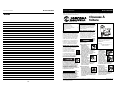
!
ADVERTENCIA
Informaciones Generales
de Seguridad (continuacion)
Área de
descarga
Tapa del
cargador
Cargador
Gatillo
Admisión
de arie
Guía para
tejas de
madera
Retén
Elemento de
Contacto
Escape
ajustable
Control de
profundidad
ajustable
(ADC)
• REQUIRE: 0,12 m
3
/min para clavar 25 clavos por
minuto a 6,21 bar
• ENTRADA DE AIRE: 6,4 mm NPT
• RANGO DE LOS CLAVOS: 22,2 mm a 4,44 cm
• CAPACIDAD DEL CARGADOR:
120 clavos por carga
• DIAMETRO DE LA ESPIGA 3,05 mm (.120") de
diámetro
• PESO: 2,49 kg
• LONGITUD: 25,72 cm
• ALTURA: 29,21 cm
• PRESION MAXIMA: 8,27 bar
• RANGO DE LA PRESION: 4,83 - 8,27 bar
Componentes y Especificaciones
de la Clavadora
Page is loading ...
Page is loading ...
Page is loading ...
Page is loading ...
Page is loading ...
-
 1
1
-
 2
2
-
 3
3
-
 4
4
-
 5
5
-
 6
6
-
 7
7
-
 8
8
-
 9
9
-
 10
10
-
 11
11
-
 12
12


Campbell Hausfeld RN1545 User manual
- Category
- Nail Gun
- Type
- User manual
- This manual is also suitable for
Ask a question and I''ll find the answer in the document
Finding information in a document is now easier with AI
in other languages
Related papers
-
Campbell Hausfeld NB0064 Operating instructions
-
-
-
-
-
-
-
-
-
Other documents
-
 Maxus MXN10100 User manual
-
Husky HDN16450AV User manual
-
MasterCraft AIR-POWERED BRAD NAILERS User manual
-
 Maxus MXN064 User manual
-
 Builder's Choice HDXD168028 Installation guide
-
-
-
-
-
 Maxus MXN10300 User manual


