PROFESSIONAL
PROFESSIONAL ROUTER TABLE
MESA PROFESIONAL DE FRESADO
OWNER'S MANUAL
Models:
171.264630 (without Floor Stand)
171.264640 (with Floor Stand)
MANUAL DEL PROPIETARIO
Modelos
171.264630 (sin base)
171.264640 (con base)
WARNING: Before
operating product,
read this manual and
follow all its Safety and
Operating Instructions.
ADVERTENCIA:
Antes de utilizar este
producto, lea este
manual y siga todas
las instrucciones de
uso y seguridad.
Sears, Roebuck and Co., Hoffman Estates IL 60179 USA
171.264630 and 171.264640 04101 Printed in U.S.A. Hecho en los Estados Unidos

General Safety Instructions for Power Tools ............................................... 3
Additional Safety Instructions for Router Tables ........................................ 4
Introduction ..................................................................................................... 6
Optional Router Table Accessories ............................................................... 7
Unpacking and Checking Contents .............................................................. 8
Parts List ......................................................................................................... 8
Assembly ....................................................................................................... 13
Installation ..................................................................................................... 24
Switch Instructions ....................................................................................... 27
Operation ....................................................................................................... 34
Espa_ol .......................................................................................................... 42
2

SAFETY GUIDELINES - DEFINITIONS
This manual contains
information that is important for
you to know and understand.
This information relates to
protecting YOUR SAFETY and
PREVENTING EQUIPMENT
PROBLEMS. To help you
recognize this information, we
use the symbols to the right.
Please read the manual and pay
attention to these sections.
I, DANGER I
URGENT SAFETY INFORMATION -
A HAZARD THAT WILL CAUSE
SERIOUS INJURY OR LOSS OF LIFE
IAWARNINGI
IMPORTANT SAFETY INFORMATION -
A HAZARD THAT MIGHT CAUSE
SERIOUS INJURY OH LOSS OF LIFE
I_C*UT'ON]
INFORMATION FOR PREVENTING
DAMAGE TO EQUIPMENT
I NOTE I
INFORMATION THAT YOU SHOULD
PAY SPECIAL A'I-FENTION TO
i-4LWARNINGI Failure to heed all safety and operating instructions and warnings regarding use of this
product can result in serious bodily injury.
1. Know your power tool
Read the owner's manual carefully. Learn its
application and limitations as well as the specific
potential hazards peculiar to this tool.
2. Ground all tools (unless double insulated)
If tool is equipped with an approved three-
conductor cord and a three-prong grounding
type plug, it should be plugged into a three hole
electrical receptacle. If adapter is used to accom-
modate a two-hole receptacle, the
adapter wire must be attached to a known
ground (usually the screw securing receptacle
cover plate). Never remove third prong.
Never connect green ground wire to a terminal.
3. Keep guards in place
Maintain guards in working order, and in proper
adjustment and alignment.
4. Remove adjusting keys and wrenches
Form a habit of checking to see that keys and
adjusting wrenches are removed from tool before
turning it ON.
5. Keep work area clean
Cluttered areas and benches invite accidents.
Floor must not be slippery due to wax or sawdust.
6. Avoid dangerous environment
Do not use power tools in damp or wet locations or
expose them to rain. Keep work area well lighted.
Provide adequate surrounding work space.
7. Keep children away
All visitors should be kept a safe distance from
work area.
8. Make workshop child-proof
Use padlocks, master switches, or remove
starter keys.
9. Do not force tools
They will do the job better and safer at the rate
for which they were designed.
10. Use the right tool
Do not force tool or attachment to do a job it was
not designed to perform.
11. Wear correct apparel
Do not wear loose clothing, gloves, neckties
or jewelry (rings, wristwatches) that may get
caught in moving parts. Non-slip footwear is
recommended. Wear protective hair covering
to contain long hair. Roll long sleeves above
the elbow.
12. Use safety goggles (Head Protection)
Wear safety goggles (must comply with ANSI
Standard Z87.1) at all times. Also, use face or
dust mask, if cutting operation is dusty, and
ear protectors (plugs or muffs) during extended
periods of operation.
13. Secure work
Use clamps or a vise to hold work when
practical. It's safer than using your hands,
and both hands are free to operate tool.
14. Do not overreach
Keep proper footing and balance at all times.
15. Maintain tools with care
Keep tools sharp and clean for best and safest
performance. Follow instructions for lubricating
and changing accessories.
3

16. Disconnect tools before servicing
Before servicing, when changing accessories
such as blades, bits, cutters, etc.
17. Avoid accidental starting
Make sure switchis in OFF positionbefore
pluggingin.
18. Use recommended accessories
Consult the owner's manual for recommended
accessories and follow the instructions.The use
of improper accessories may cause hazards.
19 Never stand on tool
Serious injurycould occurif the toolis tipped or if
the cutting tool is accidentally contacted. DO NOT
store materials above or near the tool making it
necessary to stand on the tool to reach them.
20. Check damaged parts
Before further use of the tool, any guard or
other part that is damaged should be carefully
checked to ensure that it witl operate properly
and perform its intended function. Check for
alignment of moving parts, binding of moving
parts, breakage of parts, mounting, and any
other conditions that may affect its operation. A
guard or any other part that is damaged should
be properly repaired or replaced.
21. Direction of feed
Feed work into a blade or cutter AGAINST the
direction of rotation of the blade or cutter only.
22. Never leave tool running unattended
Turn power OFF, DO NOT leave tool until it
comes to a complete stop.
23. Keep hands away from cutting area
24. Store idle tools
When not in use, toolsshould be stored in dry,
high or locked-up place - out of reach of children.
25. Do not abuse cord
Keep cord away from heat, oil and sharp edges.
26. Outdoor extension cords
When tool is used outdoors, use only extension
cords suitable for use outdoors and so marked.
27. Never use in an explosive atmosphere
Normal sparking of the motor could ignite fumes,
flammable liquids, or combustible items.
28. Drugs, alcohol, medication
Do NOT operate tool while under the influence
of drugs, alcohol, or any medication.
Read and Understand this instruction book com-
pletely BEFORE using this product.
1. Always wear eye protection that complies with
ANSI Standard Z87.1.
2. Noise levels vary widely with location. To avoid
possible hearing damage, wear ear plugs or
ear muffs when using your router table for long
periods of time.
3. For dusty operations, wear a dust mask along
with safety goggles.
4. Follow the instructions in your router owner's
manual.
5. [_,WARNINGJ Vibrations, caused by the router
during use, can cause fasteners to become loose.
Before use and periodically during use, check all
fasteners to make sure that all are tight and
secure.
6. Do not use this product until all assembly and
installation steps have been completed. Make
sure you have read and understood all safety
and operational instructions in this manual and
the router owner's manual.
7. Make sure that the router bit is properly
positioned and clamped in the router before
making any cuts.
8. Do not use the router table as a workbench or
work surface. Doing so may damage it, causing it
to be unsafe to use. A workbench should be
used for this purpose.
4
9. This product is designed for cutting flat
workpieces. Do not cut or attempt to cut
workpieces that are not flat.
10. This product is designed for cutting wood
workpieces only. Do not use to cut metal
or other non-wood materials.
11. The use of auxiliary in-feed and out-feed
supports is strongly recommended when routing
long workpieces. Otherwise those workpieces
can cause the router table to tip over.
12. Keep hands clear of the router bits and
working area.
13. Make and use a push stick to move small
workpieces across the cutting area or purchase
9-25468 Router Table Guide Master.
14. Clean the router after use. The use of a wet/dry
vac or vacuum equipment is recommended.
15. Always make sure that work surface of the router
table is clean and free from dust, chips, and
foreign particles that can interfere with the cut
you are going to make. The use of a wet/dry
vac or vacuum equipment is recommended.
16. Check the function of the guard before each
use. Remove all dust, chips, and any other
foreign particles that can affect its function.

[^ ]
17 [ABLWARNINGj Never put your fingers under
the guard when the router is plugged into an
electrical outlet or when the router bit is rotating.
18. Always use the fence to guide the workpiece.
19. Always feed the workpiece AGAINST the
rotation of the cutter or router bit.
20. Router bits are extremely sharp; be extra careful
when handling and using them.
21. Make sure that the router bits being used are
sharp or have been properly resharpened. This
will permit fast, efficient, and SAFE routing.
22. Some routers, when positionedin an upside down
position (such as on a router table), willdrop or
fall out ofthe router base when the base clamp
is loosened to adjust height or depth of cut.
Therefore, itis extremely important to support
the router from below when making these
adjustments or whenever the base clamp
is loosened.
23. Always look under the router table at the router
switch when turning the router ON or OFF. DO
NOT touch anything but the switch when doing
this. NEVER reach under the router table for any
reason when the router is running, except to turn
itOFF.
24. I_,IIALWARNING I Before making any cut, make
sure the router is turned OFF, the router bit is
not rotating, and the power cord is unplugged
from the electrical outlet. Then, make absolutely
sure that the guard clears the router bit and the
workpiece. A trial pass, with the router turned
OFF and the router bit not turning, is strongly
recommended.
IA I
25. JA_WARNING] Never leave the router table
unattended while the router is running. Turn the
router OFF before leaving the router table for
any reason.
26. If ANY part is missing, DO NOT attempt to
assemble, install, or use your router table until
the missing parts have been found or replaced
and your router table has been properly and
correctly assembled per this manual.
27. NEVER use the floor stand as a ladder and DO
NOT stand on the router table.

CraftsmanProfessionalRouterTables,Model
171.264630orModel171.264640,feature
thefollowing:
• A large, 18" x 27" (486 square inches), precision
die-cast aluminum table top, machined to ensure
true flatness and smoothness.
•The table top has an 11-1/2" x 7-3/4" opening for
mounting routers through the table top.
• An 11-1/2" x 9" router adapter plate will attach to
all Craftsman routers.
• The top is coated with a special anti-friction
coating to ensure ease of use without discoloring
or marring the workpiece.
• Dual cast scales ensure parallel and accurate fence
placements for:
• Specialty woodworking joints
• Edge and face routing
• Panel raising
• Precision 4" high x 27" long extruded aluminum
fence incorporates the following features:
• Fence guides for parallel depth-of-cut
adjustment.
• Adjustability for proper bit clearance
• Dust collection port for 2-1/2" wet/dry
vacuum hose
• Unique offset formed jointing fence for 1/16"
edge jointing
• Precision formed fence also allows you to perform
the following operations:
• Fluting, veining, and molding
• Grooving up to the center of a 6 1/2" work piece
• Dual receptacle ON/OFF switch operates both a
router, vacuum, or light simultaneously:
• Switch has overload protection
• Is UL and CUL listed
• Floor stand, on model 171.264640, places
the router table at a convenient working height
with leveling feet for uneven floors
• ALSO INCLUDED:
• Snap in router bit storage panel for both 1/2"
and 1/4" shank router bits
• Miter gauge for cross grain routing at 90° and
60° in two directions

9-25188 Router Table Switch
• Switch mounts to the front of all Craftsman
router tables
• Front switch operates two receptacles on the
back of the switch
• Large switch paddle for ease in turning the
switch OFF
• Removable key prevents unauthorized use
when removed from the switch
• Has built-in circuit breaker
9-25468 Craftsman Guide Master Router Table
Push Shoe with Hold Down Stick
• Ideal for handling small work pieces on a
router table
• Aids in accurate measurement and router table
set-up
• Transforms into a miter gauge
• Provides a quick set-up for making 1/2" sliding
dovetail joints
9-26479 Craftsman Professional Large Router
Adapter Plate
• Molded glass-filled polycarbonate plastic
adapter plate mounts most non-Craftsman
routers to the 171.264630 and the
171,264640 Professional Router Tables
• Easy to follow instructions and mounting
templates supplied
• Adapter plate mounts to the router table using
fasteners supplied with router table
• Fasteners for mounting the router to the
adapter plate are not included and must
obtained separately
IMPORTANT NOTE: The drilling and the
countersinking of holes in the adapter plate
are necessary in order to mount the router
to the adapter plate. The screw heads must
be slightly below the top surface of the
adapter plate.
9-26473 Craftsman Bit Storage Panel
• Easy snap-in installation
• Provides easy and convenient storage for up to
18 router bits
• Holds a mix of both 1/4" and 1/2" shank
router bits
9-26471 Craftsman Feather Board
• Mounts to 171.264630 and the 171.264640
Professional Router Tables only; cannot
be used on any other Craftsman or
non-Craftsman router tables
• Feather boards apply pressure to a workpiece
vertically down towards the table top and
or sideways towards the router table fence pro-
viding better control of the work piece
• Adjustable for both small and large
work pieces
• Not to be used on any other type of machinery
or accessory
9-26472 Precision Router Table Fence Assembly
• Mounts to all Craftsman Professional
Router Tables
• Extruded aluminum fence is fully adjustable
measuring 4" high and 27" long
• Fence opening is adjustable for different size
router bits providing greater support
• Exclusive "keyed"jointing feature straightens
workpiece edges for gluing
• Fence assembly has 2-1/2" diameter dust port
for wetJdry vacs with 2-1/2" diameter hoses
• Clear see through guard allows viewing of
the work area
• Incorporates T-slot design for mounting
feather boards
9-26477 Craftsman Enclosure Kit
• Converts the 9-26478 Craftsman Floor Stand
to a convenient storage cabinet
• Includes three panels, door, hinge, magnetic
latch, knob, and mounting hardware
9-26478 Craftsman Floor Stand
• Places router table at optimal working height
• Adjustable non-slip foot pads for leveling table
on uneven floor surfaces
• Two heavy-duty steel shelves for storage
• Will accept all Craftsman bench top router
tables available after 1997

Referto PartsListbelowandonpages9-12
I^ 1
• IA_WARNINGI If ANY of the parts is missing,
DO NOT attempt to assemble, install, or use your
router table until the missing parts have been found
or replaced and your router table has been properly
and correctly assembled per this manual.
• For missing parts or technical assistance, call
1-800-624-0488.
• In order to simplify handling and to minimize any
damage that may occur during shipping, your
router table comes unassembled.
• Separate all parts from the packaging materials
and check each part against the illustrations and
the parts lists on pages 9-12, to make sure that all
parts have been included. Do this before discarding
any of the packaging material.
WHENASSEMBLINGROUTERTABLE171.264640,DISREGARDOWNER'SMANUALFURNISHEDWiTHFLOORSTANDMODEL9-26478.
Quantity
Key No. Part No. Description Model Model
9-26463 9-26464
A ROUTER TABLE ASSEMBLY
1 29LCN-1223 Router Table 1 1
2 29LCN-1224 Fence Support Bracket 2 2
3 29LCN-997 Fence Guide (Yellow) 2 2
4 29LCN-1174-2 Large Clamping Knob (Yellow) 2 6
5 29LCN1229 Router Adapter Plate (Black) 1 1
6 29LCN-1230 Lower Fence 2 2
7 29LCN-1232 Upper Fence 1 1
8 29LCN-1231-2 Fence Clamping Knob (Yellow) 4 4
9 29LCN-1233-01 Dust Collector (Black) 1 1
10 29LCN-t 234 Upper Fence End Cap (Right Side, Black) 1 1
1t 29LCN-1235 Upper Fence End Cap (Left Side, Black) 1 1
12 29LCN-1236 Lower Fence End Cap (Right Side, Black) 2 2
13 29LCN-1237 Lower Fence End Cap (Left Side, Black) 2 2
14 29LCN-1238 Overhead Guard (Clear) 1 1
15 29LCN-1239 Guard Shaft 1 1
16 29LCN-1240 Leg Reinforcement 4 4
17 29LCN-1241-11 Table Top Insert w/1" Dia. Hole (Yellow) 1 1
18 29LCN-1241-12 Table Top Insert w/2" Dia. Hole (Yellow) 1 1
19 29LCN-1241-13 Table Top Insert w/2-3/4" Dia. Hole (Yellow) 1 1
20 29LCN-1242-02 Table Leg (Black) 2 2
21 29LCN-1243-02 Table Leg Fascia (Black) 1 1
22 29LCN-1244 Power Bar Switch Assembly 1 1
23 29LCN-1018 Switch Key 1 1
24 29LCN-1176 Protractor Head 1 1
25 29LCN-1119 Miter Bar 1 1
26 29LCN-1175-2 Small Clamping Knob (Yellow) 1 1
27 29LCN-12-02 Feather Board 2
28 29LCN-1247-02 Router Table Leg Insert Cover (Black) 1 1
29 29LCN-1248-02 Router Table Leg Insert Router Bit Storage (Black) 1 1

®
®
Fence Assembly
Switch Assembly
Miter Gauge
o@
Feather Board (#9-26464 only)
G
@
Table Top Inserts
©÷

Quantity
Key No. Part No. Description Model Model
9-26463 9-26464
B FASTENERS
30 29LCN-1016 1/4-20 Weld Nut 4 4
31 29A-1113 #10-32 KEPS Nut 21 65
32 29A-1172-1 1/4-20 KEPS Nut 8 8
33 29LCN-979-1 #10-16 x 1/2" Ig. BT Pan-head Self-Tapping Phillips Screw 1 1
34 29LCN-1220-1 #10-16 x 5/8" Ig. BT Countersunk Self-Tapping Phillips Screw 6 6
35 29LD-123-2 #10-32 ESNA Stop Nut 12 12
36 29LD-841-2 #10-32 x 5/8" Ig. Countersunk Phil. Head Machine Screw 3 3
37 29LD-841-12 #10-32 x 1" Ig. Countersunk Phil. Head Machine Screw 4 4
38 29LD-841-14 5/16-18 x 1-1/4" Ig. Countersunk Phil. Machine Screw 3 3
39 29A-306-37 13/64" ID x 9/16" OD x 0.040" thick Washer 1 1
40 29A-306-38 9/32" ID x 5/8" OD x 1/16" thick Washer 16 24
41 29A-306-26 #10-24 x 7/8" Ig. Carriage Bolt 1 1
42 29A-310-07 1/4-20 x 1-3/4" [g. Carriage Bolt 4
43 29A-310-24 1/4-20 x 1-1/2" Ig. Carriage Bolt 10 14
44 29A-970-5 #10-32 x 1/2" Ig. Truss Head Machine Screw 4 48
45 29A-970-9 #10-32 x 3/4" Ig. Truss Head Machine Screw 9 9
46 29A-970-13 1/4-20 x 5/8" Ig. Truss Head Machine Screw 6 6
47 29A-1257-2 #10-32 x 3/4" Ig. Countersunk Socket Head Screw 8 8
48 29A-242-14 1/4-20 Hex Machine Screw Nut 6 6
49 29A-249-1 1/8" Hex Key (Allen Wrench) 1 1
10

Use the guide below to identify the fasteners included with your Router Table.
Numbers in bold correspond to the key numbers in the parts list on page 10.
@@
(30) 1/4-20 Weld Nut
@
(39) 13/64" ID x 9/16" OO
x 0.040" thick Washer
@@
(31) #10-32
KEPS Nut
©
(40) 9/32" ID x 5/8" OD x
1/16" thick Washer
@@ ©®@@
(32) 1/4-20 (38) #10-32 (48) 1/4-20 Hex
KEPS Nut ESNA Nut Machine Screw Nut
(43) 1/4-20 x 1-1/2" Ig. Carriage Bolt
(41) #10-24 x 7/8" Ig. Round Head
Square Neck Bolt
(42) 1/4-20 x 1-3/4" Ig. Carriage Bolt
(44) #10-32 x 112" Ig. Truss Head
Phillips Machine Screw
(33) #10-16 x 1/2" Ig. BT
Pan-head Self-Tapping
Phillips Screw
(36) #10-32 x 518° Ig. Countersunk
Phillips Machine Screw
(48) #10-32 x 3/4" Ig.Truss Head Phillips
Machine Screw
(46) 1/4-20 x 5/8" Ig Truss Head Phillips
Machine Screw
(34) #10-16 x 5/8" Ig. BT
Countersunk Self-Tapping (36) 5/16-18 x 1-1/4" Ig. Countersunk Phillips Machine Screw
Phillips Screw
(37) #10-32 x 1" Ig, Countersunk Phillips
Machine Screw
(47) #10-32 x 3/4" Ig Countersunk Socket
Head Screw
(49) 1/8" Hex Key (Allen Wrench)
11

Quantity
Key No. Part No. Description Model Model
9-26463 9-26464
C FLOOR STAND ASSEMBLY
50 29LCN-1249-02 Floor Stand Leg (Black) 4
51 29LCN-1250-02 Floor Stand Shelf (Black) 2
52 29LCN-1118 Leveling Bracket 4
53 29LCN-1117 Leveling Foot (Black) 4
54 29LCN-1174-2 Large Clamping Knob (Yellow) 4
D OWNER'S MANUAL
49LCN-75 Craftsman Professional Router Table Owner's Manual 1 1
12

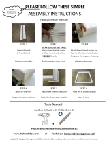
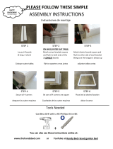
ASSEMBLING THE ROUTER TABLE
TOOLS REQUIRED (not included)
• Phillips screwdriver
• Small sized adjustable wrench
• Tape with adhesive backing
ROUTER TABLE LEGS (FIGURES 1A-lC)
1. Insert eight 1/4-20x1-1/2" long carriage
bolts (43) through the router table top as
shown in Figure 1A.
2. Place a strip of tape with adhesive backing
over the bolts to temporarily hold them
in place.
3. Turn the router table top upside down.
4. Place a leg reinforcement over each set of
carriage bolts as shown in Fig. lB.
5. Assemble one of the legs to the router table
as shown in the figure.
6. Assemble a 9/32" ID x 5/80D" x 1/16" thick
washer (40) and a 1/4-20 "KEPS" nut (32)
onto each of the bolts.
7. Securely tighten the fasteners.
8. Repeat this procedure for the other side of
the router table as shown in Fig. 1C.
9. Securely tighten the fasteners.
10. Turn the router table right side up.
11. Remove the tape holding the bolts in place.
Figure
1A _" lc/4_2tgl "10/2;
Figure 1B
9/32 x 5/8 x 1/16" washer
1/4-20 KEPS nut
Leg _/
reinfor_
Figure lC
13

ATTACH THE SWITCH TO THE FASCIA
(FIGURE 2 AND DETAIL 2A)
Refer to the section "OPERATION-OPERATING
THE SWITCH" for instructions on connecting
and using the switch.
Attach the switch to the back of the fascia
using two #10-32 KEPS nuts (31) and two
#10-32 x 3/4" truss head machine screws (45)
(Figure 2).
The toothed washer on the KEPS nut
must face away from the switch assembly
as shown in detail 2A.The hex portion of
the KEPS nut fits into the hex-shaped
recess in the back of the switch case.
2. TIGHTEN all screws SECURELY.
ATTACH THE FASCIA TO THE ROUTER
TABLE (FIGURE 3 AND DETAIL 3A)
NOTE: The fascia assembles to the inside of
both the table legs and the router table top,
1 Turn the router table upside down.
2. Line up the holes on the fascia with the holes
in the table legs and the two slots on the front
of the router table top.
NOTE: in the following two steps, the
toothed washer on the KEPS nut must
face away from the fascia as shown in
Detail 3A.The hex portion of the KEPS nut
fits into the hex shaped recess in the back
of the fascia.
3.
Attach the fascia to the router table top using
two #10-32 x 3/4" long truss head machine
screws (45) and two #10-32 KEPS nuts (31),
as shown in Figure 3.
4,
Attach the fascia to the legs using four
#10-32 x 3/4" long truss head machine screws
(45) and four #10-32 KEPS nuts (31), as
shown in Figure 3.
5. TIGHTEN all screws SECURELY.
IMPORTANT:
For Router Table Models 171.264630, which
does NOT include a floor stand, continue with
the next section, on page 15.
For Router Table Models 171.264640, which
does include a floor stand, skip to page 17 and
continue with the section "ASSEMBLING THE
FLOOR STAND".
Figure 2 #10-32 x 314" truss
head screws
/ ' _ 2 " "
Switch _ _ i:
-32 KEPS nuts
Detail 2A
Figure 3
tea of Detail 3A _<'_- _
Detail 3A
_) #10-32 x 3/4" truss
head screws
Q "_- #10-32 KEPSnuts
14

MOUNTING THE ROUTER TABLE TO A
WORK SURFACE OR WORKBENCH
Ii_,I=LWARNINGI The router table must always be
FIRMLY and SECURELY mounted to a work surface
before use. Failure to do so could cause the router
table to tip over or slide, resulting in property
damage and/or serious personal injury.
TOOLS REQUIRED (not included)
• Phillips screwdriver
• Small sized adjustable wrench
• Electric or hand drill with drill bits (depending on
mounting method used)
• Fasteners (not included):
• Four #14, #16, or #18 x 2" pan head wood
screws (for solid wood work surfaces or
workbenches), or
• Four 5/16" pan head machine screws, washers,
and hex nuts, or
• Clamps.
METHOD 1 (FIGURE 4)
1. Set the router table on a workbench or other
stable and sturdy surface, with the FRONT
(switch side) of the router table facing
toward you.
2. While holding the router table in the desired
position, mark the location of the four mounting
holes (one in each corner).
3. Remove the router table from the workbench and
set it aside.
4. Drill a 1/8" pilot hole (for wood screws) or an
appropriately sized hole (for machine screws) at
the marked locations.
5. Place the router table on the workbench and
align the mounting holes in the router table legs
with the holes drilled in the work bench.
6.
Secure the router table in place using wood
screws (not provided) or machine screws,
washers, and nuts (not provided). If using
wood screws, applying a little soap to the
screw threads will make it easier to thread
the screws into the pilot holes.
Figure 4
Figure 5
METHOD 2 (FIGURE 5)
1, Set the router table on a workbench or other
stable and sturdy surface, with the FRONT
(switch side) of the router table facing
toward you.
2.
Secure the router table legs to the workbench
with clamps, making sure to tighten them
SECURELY.
IMPORTANT: Be sure the placement of the
clamps will not interfere with operation of the
router table.
7. TIGHTEN all screws SECURELY.
15

ALTERNATE METHOD (FIGURE 6)
1. Cut a board 18-1/4" wide by 29" long from a
piece of 3/4" thick wood.
2, Set the router table on the board, with the
FRONT (switch side) of the router table facing
toward you, so that the spacing between the
router table legs and the edges of the board is
equal on all sides.
3. While holding the router table in the desired
position, mark the location of the four mounting
holes (one in each corner).
4. Remove the router table from the board and set
it aside.
5. Drill a 1/8" pilot hole (for wood screws) at the
marked locations.
6. Place the router table on the board and align the
mounting holes in the router table legs with the
holes drilled in the board.
7,
Secure the router table in place using wood
screws (not provided). Applying a little soap to
the screw threads will make it easier to thread
the screws into the pilot holes.
8. TIGHTEN all screws SECURELY.
g. Place the router table on a workbench or other
stable and sturdy surface. Firmly secure the
board to the workbench with screws, clamps,
or other suitable means.
Figure 6
16

ASSEMBLING THE ROUTER TABLE FLOOR STAND
(Model 9-26464)
TOOLS REQUIRED (not included)
• Phillips screwdriver
• Small sized adjustable wrench
ATTACHING THE LEVELING FEET TO THE
LEGS (FIGURE 7)
1. Attach a leveling bracket to the inside of each
of the four legs using three #10-32 KEPS (31)
nuts and three #10-32 x 1/2" long truss head
machine screws (44).
NOTE: To simplify assembly and leveling of the
stand, set all four leveling brackets to their fully
retracted position and tighten the fasteners. You
may need to adjust the leveling brackets to your
floor surface later.
2. Slide a rubber leveling foot onto the end of each
leveling bracket.
Figure 7 Leveling bracket Levelir
#10-32 x 1/2_ _,_
machine
screws
foot
/
D D
J
ATTACHING THE LEGS TO THE SHELVES
(FIGURE 8)
NOTE: Both shelves for the floor stand are identical,
as are all four legs.
1,
Place a shelf upside down (flat side down,
mounting flanges facing up) on the floor or
other stable work surface. This will be the
top shelf of the router table floor stand.
2.
Using four #10-32 KEPS nuts (31) and four
#10-32 x 1/2" Ig. truss head machine screws
(44), attach a leg to each corner, as shown in
Figure 8.
SECURELY TIGHTEN all fasteners.
3.
Attach the lower shelf, with the mounting flange
facing the leveling feet, to the legs using four
#10-32 KEPS nt_ts (31) and four #10-32 x 1/2"
Ig. truss head machine screws (44) on each leg.
SECURELY TIGHTEN all fasteners.
NOTE: It may be easier to align and attach the
lower shelf if you turn the stand on its side.
#10-32
KEPS nuts
#10-32 x 1/2"
machine
screws
17

ATFACHING THE ROUTER TABLE TO THE
FLOOR STAND (FIGURE 9)
1, Turn the floor stand upright and set it on its feet.
2. Place the router table on the floor stand and
align the holes in the router table legs with the
square holes in the corners of the top shelf of
the floor stand.
3. From underneath, slide a 1/4-20 x 1-3/4" carriage
bolt (42) up through the hole in the top floor stand
shelf and router table leg, and secure with a
9/32" ID x 5/8" OD x 1/16" washer (40) and a
large clamping knob. Repeat for the other
three corners.
LEVELING THE FLOOR STAND
1. Place the router table and floor stand in the
desired working location. When selecting a
location, be sure to keep in mind sufficient
working space, lighting, and proximityto a
suitable electrical outlet.
2. Adjust the leveling brackets as needed to make
sure that the router table surface is level and that
all four leveling feet are in solid contact with the
floor. An assistant may be helpful in keeping the
table level and stable until all four leveling legs
are securely tightened.
Figure 9
Clampin_
knob and I III I _ 1 __ I I
i I
L
1
18

INSTALLING TABLE LEG INSERTS IN THE TABLE LEGS
TABLE LEG INSERTS (FIGURE 10)
The router table includestwo table leg inserts:
• Router bit storage panel for convenient bit storage
• Cover panel
If the table leg inserts have not been installed on the
router table legs, proceed as follows:
1. Place the table leg insert into the opening in the
table leg so that it is positioned at the very top of
the opening.
2. Press the insert in so that it is completely flush
with the leg.
3. Push the insert down as far as it willgo to lock it
in place.
Figure 10
h wn
ASSEMBLING THE MITER GAUGE
ASSEMBLE THE MITER GAUGE
(FIGURE 11A AND FIGURE 11B)
1, Assemble the protractor head to the miter bar, as
shown in Figure 11A, using a #10-16 x 1/2" long
type BT pan-head self-tapping screw (33).
2. Tighten the self-tapping screw into the protractor
head so that the screw touches the miter bar but
still provides resistance when the protractor head
is rotated.
NOTE: the screw will resist turning when being
threaded into the hole as the screw is cutting
and forming a thread in the protractor head,
3. Assemble the knob, the 13/64" ID x 9/16" OD x
.040" thick washer (39), and the #10-24 x 7/8"
carriage bolt (41) to the miter bar and protractor
head as shown in Figure 11B.
4. TIGHTEN the knob SECURELY.
Figure 11A
S
-__ #10-16 x 1/2"
self-tapping screw
, Miter bar
ro, aotor
Figure 11B
Small clamping
knob
_ _ Washer
Protractor
#10-24 x 7/8"
\, carriage bolt
19

ASSEMBLING THE FENCE
TOOLS REQUIRED (not included)
• Phillips screwdriver
• Small sized adjustable wrench
FENCE SUPPORT BRACKETS (FIGURE 12)
1.
2*
,
Insert a #10-32 KEPS (31) nut into each of the
hex-shaped openings in the fence guides, with
the toothed washer facing towards the fence
guide as shown in Detail 12A.
NOTE: The KEPS nuts should "bottom-out" in
the hex-shaped openings on the fence guides.
It may be helpful to place the fence guides on
a flat surface and lightly tap the nuts in with
a small hammer.
Attach the fence guides to the fence support
brackets using two #10-32 x 1/2" long truss head
machine screws (44), as shown in Figure 12.
DO NOT tighten the screws at this time.
The orientation of the fence guide in relation
to the fence support bracket must be as
shown.
Loosely assemble two 1/4-20 nuts (48) and
1/4-20 x 5/8" long truss head machine screws (46)
to each fence support bracket, as shown in Figure
12. It is not necessary to tighten the fasteners at
this time.
Figure 12 -- 1/4-20x 5/8"
(__ L- --(-_/_ machine screws
/ ,\ J#,o32xl,2
Fence / . _ _ Fence
support v// '\ '_/ guide
bracket , _/,
#10-32 KEPS nuts_
Detail 12A Fence
guide
_ #10-32KEPS _ /nuts
r\
2O
Page is loading ...
Page is loading ...
Page is loading ...
Page is loading ...
Page is loading ...
Page is loading ...
Page is loading ...
Page is loading ...
Page is loading ...
Page is loading ...
Page is loading ...
Page is loading ...
Page is loading ...
Page is loading ...
Page is loading ...
Page is loading ...
Page is loading ...
Page is loading ...
Page is loading ...
Page is loading ...
Page is loading ...
Page is loading ...
Page is loading ...
Page is loading ...
Page is loading ...
Page is loading ...
Page is loading ...
Page is loading ...
Page is loading ...
Page is loading ...
Page is loading ...
Page is loading ...
Page is loading ...
Page is loading ...
Page is loading ...
Page is loading ...
Page is loading ...
Page is loading ...
Page is loading ...
Page is loading ...
Page is loading ...
Page is loading ...
Page is loading ...
Page is loading ...
Page is loading ...
Page is loading ...
Page is loading ...
Page is loading ...
Page is loading ...
Page is loading ...
Page is loading ...
Page is loading ...
Page is loading ...
Page is loading ...
Page is loading ...
Page is loading ...
Page is loading ...
Page is loading ...
Page is loading ...
Page is loading ...
Page is loading ...
Page is loading ...
Page is loading ...
Page is loading ...
/