Page is loading ...

()
■■■■■■■
■■■■■■■
■■■■■■■
■■■■■■■
■■■■■■■
■■■■■■■
■■■■■■■
■■■■■■■
■■■■■■■
■■■■■■■
■■■■■■■
■■■■■■■
■■■■■■■
■■■■■■■
User's Guide
Server HX4600

xxx

()
■■■■■■■
■■■■■■■
■■■■■■■
■■■■■■■
■■■■■■■
■■■■■■■
■■■■■■■
■■■■■■■
■■■■■■■
■■■■■■■
■■■■■■■
■■■■■■■
■■■■■■■
■■■■■■■
User's Guide
Server HX4600

Proprietary Notice and Liability Disclaimer
The information disclosed in this document, including all designs and related
materials, is the valuable property of Packard Bell NEC, Inc. and/or its
licensors. Packard Bell NEC, Inc. and/or its licensors, as appropriate, reserve all
patent, copyright and other proprietary rights to this document, including all
design, manufacturing, reproduction, use, and sales rights thereto, except to the
extent said rights are expressly granted to others.
Actual performance of products discussed in this document are dependent upon
factors such as system configuration, customer data, and operator control. Since
implementation by customers of each product may vary, the suitability of
specific product configurations and Packard Bell NEC, Inc. applications must be
determined by the customer and is not warranted by Packard Bell NEC, Inc.
To allow for design and specification improvements, the information in this
document is subject to change at any time, without notice. Reproduction of this
document or portions thereof without prior written approval of Packard Bell
NEC, Inc. is prohibited.
Trademarks
INTEL is a registered trademark of Intel Corporation.
MS-DOS is a registered trademark of Microsoft Corporation.
Pentium is a registered trademark of Intel Corporation.
All other product, brand, or trade names used in this publication are the trademarks or
registered trademarks of their respective trademark owners.
PN: 456-01502-001nnnnnnnnnnn
s
SS
S
Copyright 1999
Packard Bell NEC, Inc.
1 Packard Bell Way
Sacramento, CA 95828-0903
All Rights Reserved

Contents iii
Contents
Proprietary Notice and Liability Disclaimer
Using This Guide ................................................................................. vii
Text Conventions................................................................................ viii
Related Documents ............................................................................... ix
Safety Notices ........................................................................................ x
Safety Notices for Users Outside of the U.S.A. and Canada........... xi
Care and Handling ............................................................................... xii
System Overview ................................................. 1-1
Overview............................................................................................. 1-2
System Feature Summary.............................................................. 1-3
Expanding the Server as Needs Grow ........................................... 1-4
Configuration Constraints.............................................................. 1-4
Chassis ................................................................................................ 1-5
Status LED Indicator Descriptions ................................................ 1-6
Opening the Front Doors ............................................................... 1-7
Chassis Features and Controls....................................................... 1-9
System Board Features ..................................................................... 1-11
Processor...................................................................................... 1-16
Memory ....................................................................................... 1-16
Bus Master I/O Expansion Slots.................................................. 1-16
Real-Time Clock/Calendar .......................................................... 1-16
BIOS ............................................................................................ 1-16
Video ........................................................................................... 1-17
SCSI Controller ........................................................................... 1-17
Peripheral Controller ................................................................... 1-17
External Device Connectors ........................................................ 1-17
Keyboard and Mouse................................................................... 1-18
Fans.............................................................................................. 1-18
Peripheral Devices ............................................................................ 1-18
Ultra2 Wide SCSI-2 Hard Drive Bays......................................... 1-18
Removable Media Drive Bays..................................................... 1-19
System Power ................................................................................... 1-20
Software Locks via the BIOS Setup ................................................. 1-21
Setting Up Your System ....................................... 2-1
Selecting a Site.................................................................................... 2-2
Unpacking the System ........................................................................ 2-3
Moving the System to the Site ............................................................ 2-3
Getting Familiar with the System ....................................................... 2-4
Making Connections ........................................................................... 2-4
Connecting the Power Cords .............................................................. 2-6
Powering On Your System ................................................................. 2-7
Configuring Your System ..................................... 3-1
Configuring Your System................................................................... 3-2
BIOS Setup Utility.............................................................................. 3-3
When to Use the BIOS Setup Utility............................................. 3-3
Using the BIOS Setup Utility ........................................................ 3-4
BIOS Setup Configuration Settings............................................... 3-5
Exiting BIOS Setup ..................................................................... 3-11
Symbios Configuration Utility.......................................................... 3-12

iv Contents
Running the Symbios Configuration Utility ................................3-12
Changing the Adapter and Device Configurations ......................3-13
Configuring the RAID Controller .....................................................3-15
Configuring System Jumpers and Switches ......................................3-16
Before You Begin ........................................................................3-16
Configuring I/O Riser Board Function Select Switches ..............3-16
Configuring Memory Board Function Jumpers ...........................3-18
Configuring System I/O Board Switches and Jumpers................3-19
Setting Switches and Jumpers......................................................3-21
BIOS ............................................................................................3-22
Updating the BIOS..................................................................3-22
Resetting the CMOS NVRAM ....................................................3-22
Clearing and Changing the Password ..........................................3-23
Upgrading Your System ........................................ 4-1
Precautions ..........................................................................................4-3
Preparing Your System for Upgrade...................................................4-5
Equipment Log...............................................................................4-5
Removing the Front Doors.............................................................4-6
Installing the Front Doors ..............................................................4-6
Removing the Top Cover and Side Panels.....................................4-6
Installing the Top Cover and Side Panels ......................................4-9
Modifying the System I/O Board ......................................................4-10
Replacing the Non-Volatile Memory (NVRAM) ........................4-10
Replacing the Real-time Clock Battery........................................4-11
DIMMs..............................................................................................4-13
Installing DIMMs.........................................................................4-14
Removing DIMMs .......................................................................4-15
Processors..........................................................................................4-16
Installing a Processor Cartridge ...................................................4-17
Removing a Processor Cartridge or Termination Board..............4-20
Option Boards ...................................................................................4-20
Installation Considerations...........................................................4-21
Controller/Adapter Hardware Configurations..............................4-22
Installing an Option Board...........................................................4-23
Removing an Option Board .........................................................4-25
Power Supply ....................................................................................4-26
Installing a Power Supply ............................................................4-26
Removing a Power Supply...........................................................4-27
Hot-Swapping a Power Supply ....................................................4-27
Removable Media Devices................................................................4-28
Installing a 5 1/4-Inch Device or 3 1/2-Inch Diskette Drive........4-30
Removing a 5 1/4-Inch Device or 3 1/2-Inch Diskette Drive ......4-34
Hard Disk Drives...............................................................................4-35
Installing a Hard Drive.................................................................4-36
Removing a Hard Drive ...............................................................4-39
Hot-Swapping a Hard Drive ........................................................4-40
Problem Solving ................................................... 5-1
Resetting the System ...........................................................................5-2
Troubleshooting Checklists.................................................................5-2
Initial System Startup.....................................................................5-2
Running New Application Software ..............................................5-3
After System Has Been Running Correctly ...................................5-4

Contents v
Diagnostic Testing .............................................................................. 5-5
Error Checking .............................................................................. 5-5
Troubleshooting Guide .................................................................. 5-5
Preparing the System for Diagnostic Testing........................... 5-5
Monitoring POST While Running............................................ 5-6
Verifying Proper Operation of Key System Indicators ............ 5-6
Confirming Loading of the Operating System ......................... 5-7
Specific Problems and Corrective Actions ......................................... 5-7
Power LED Does Not Light .......................................................... 5-7
System Cooling Fans Do Not Rotate............................................. 5-7
No Characters Appear On Screen.................................................. 5-8
Characters are Distorted or Incorrect............................................. 5-9
Floppy Disk Drive Activity LED Does Not Light......................... 5-9
Hard Disk Drive Activity LED Does Not Light............................ 5-9
Error Messages ................................................................................. 5-10
Alarm Indication during POST.................................................... 5-10
Alarm Indication During System Operation................................ 5-17
Error Code Hardware Reference....................................................... 5-25
Status LEDs ...................................................................................... 5-29
System Cabling .................................................... A-1
Before You Begin .............................................................................. A-2
Static Precautions............................................................................... A-2
RAID Configuration .......................................................................... A-3
Memory Configurations........................................ B-1
Memory DIMM Configurations .........................................................B-2
Management Workstation Application.................. C-1
Overview.............................................................................................C-2
Remote Console.............................................................................C-3
Remote Drive.................................................................................C-3
MWA System Requirements ..............................................................C-3
Installing MWA ..................................................................................C-4
Creating a Server System Generation Diskette (SG).....................C-4
Configuring Server BIOS Setup ....................................................C-6
Installing MWA on the Management PC ......................................C-6
Registering SG Information on MWA ..........................................C-6
MWA Main Window ..........................................................................C-7
Toolbar ..........................................................................................C-7
Main Menu ....................................................................................C-8
Pop-Up Menus.............................................................................C-11
Using MWA......................................................................................C-12
Opening a Server Window ..........................................................C-12
Connecting and Disconnecting the Server...................................C-12
Using a Remote Drive .................................................................C-13
Setting and Clearing Server Pause...............................................C-13
Recovering from an SOS.............................................................C-14
Alerting ESMPROTM.................................................................C-15
Dialog Boxes ....................................................................................C-15
Select a Server Dialog Box..........................................................C-15
Server Properties Dialog Box ......................................................C-15
Default Server Properties Dialog Box .........................................C-16
Create/Copy FD Image File Dialog Box .....................................C-17

vi Contents
Server Summary Dialog Box ...................................................... C-17
Delete Logged Messages Dialog Box......................................... C-17
Data Dialog Box ......................................................................... C-18
Temporary Change to Remote Drive Dialog Box....................... C-18
SOS Receive Dialog Box............................................................ C-19
Troubleshooting ............................................................................... C-20
Hardware Event Log .............................................D-1
Introduction ........................................................................................D-2
Viewing the Hardware Event Log......................................................D-2
Component Locations ........................................................................D-4
Glossary
Equipment Log
Index

Using This Guide vii
Using This Guide
This User’s Guide provides a quick reference to information about your system. Its goal is to
familiarize you with your system and the tasks necessary for system configuring and
upgrading.
This guide contains the following information:
Chapter 1, “System Overview” provides an overview of your system and describes your
system’s major system components. See this chapter to familiarize yourself with your
system.
Chapter 2, “Setting Up Your System” tells you how to select a site, unpack the system,
make cable connections, and power on your system.
Chapter 3, “Configuring Your System” tells you how to configure the system and
provides instructions for running the BIOS Setup Utility and the Symbios Configuration
Utility. It also provides information on configuring system jumpers and switches.
Chapter 4, “Upgrading Your System” provides you with instructions for upgrading your
system with additional processors, optional memory, option cards, and peripheral
devices.
Chapter 5, “Problem Solving” contains helpful information for solving problems that
might occur with your system.
Appendix A, “System Cabling” includes cabling information for the RAID controller
installed in your system.
Appendix B, “Memory Configurations” defines the allowable memory configurations
for your system.
Appendix C, "Management Workstation Application (MWA)" provides you with
information on using MWA for managing your server remotely in a network
environment.
Appendix D, "Hardware Event Log" helps you locate a hardware component in your
system that the Hardware Event Log listed as causing an error in your system.
“Glossary” defines the standard acronyms and technical terms used in this manual.
“Equipment Log” provides you with a sample equipment log for documenting the
system configuration and future updates you may make to your system.

viii Using This Guide
Text Conventions
This guide uses the following text conventions.
Warnings, cautions, and notes have the following meanings:
!
WARNING
Warnings alert you to situations that could result in serious personal injury or
loss of life.
!
CAUTION
Cautions indicate situations that can damage the system hardware or
software.
Note:
Notes give important information about the material being
described.
Names of keyboard keys are printed as they appear on the keyboard. For example, Ctrl,
Alt, or Enter.
Text or keystrokes that you enter appear as boldface type. For example, type abc123 and
press ENTER.
File names are printed in uppercase letters. For example, AUTOEXEC.BAT.

Using This Guide ix
Related Documents
In addition to this guide, the following system documentation is included with your server
either as electronic files on E
XPRESS
B
UILDER
or as paper copy shipped with your server.
System Release Notes
Release Notes provide you with the latest information about your system. This
information was not available at the time your user’s guide was developed.
Getting Started Sheet
The Getting Started Sheet provides several easy-to-follow steps to become familiar with
your server documentation and to complete your installation successfully.
Network Operating System Configuration Guide
This guide contains supplemental instructions needed to install and configure your
server Windows NT v4.0, Novell NetWare v4.2, Santa Cruz Operation (SCO)
OpenServer Release 5.05, and SCO UnixWare 7.01 Network Operating Systems. This
document is intended to complement the more detailed procedural documents available
from the vendor of the network operating system.

x Using This Guide
Safety Notices
!
Caution: To reduce the risk of electric shock which could cause personal injury, follow
all safety notices. The symbols shown are used in your documentation and on your
equipment to indicate safety hazards.
Warning: Lithium batteries can be dangerous. Improper handling of lithium batteries
may result in an explosion. Dispose of lithium batteries as required by local ordinance or
as normal waste if no local ordinance exists.
Warning: The detachable power supply cords are intended to serve as the disconnect
devices.
Warning: This equipment has two 3-wire, grounded power cords. To prevent electrical
hazards, do not remove or defeat the ground prong on the power cords. Replace any
power cord that gets damaged. Contact your dealer for an exact replacement.
Warning: The DC push-button on/off switch on the front panel does not turn off the
system AC power. Also, +5vdc is present on the system board whenever the AC power
cord is connected between the system and an AC outlet. Before doing the procedures in
this manual, make sure that your system is powered off and unplug the AC power cords
from the back of the chassis. Failure to disconnect power before opening your system
can result in personal injury and equipment damage.
In the U.S.A. and Canada, each power cord must be a UL-listed detachable power cord (in
Canada, CSA-certified), type ST or SJT, 16 AWG, 3-conductor, provided with a molded-on
NEMA type 5-15 P plug cap at one end and a molded-on cord connector body at the other end.
The cord length must not exceed 9 feet (2.7 meters).
Outside the U.S.A. and Canada, the plug must be rated for 250 VAC, 10 amp minimum, and
must display an international agency approval marking. The cord must be suitable for use in the
end-user country. Consult your dealer or the local electrical authorities if you are unsure of the
type of power cord to use in your country. The voltage change occurs via a switch in the power
supply.
Warning: Under no circumstances should the user attempt to disassemble the power
supply. The power supply has no user-replaceable parts. Inside the power supply are
hazardous voltages that can cause serious personal injury. A defective power supply
must be returned to your dealer.

Using This Guide xi
Safety Notices for Users Outside of the U.S.A. and Canada
PELV (Protected Extra-Low Voltage) Integrity: To ensure the extra-low voltage
integrity of the equipment, connect only equipment with mains-protected electrically-
compatible circuits to the external ports.
Remote Earths: To prevent electrical shock, connect all local (individual office)
computers and computer support equipment to the same electrical circuit of the building
wiring. If you are unsure, check the building wiring to avoid remote earth conditions.
Earth Bonding: For safe operation, only connect the equipment to a building supply
that is in accordance with current wiring regulations in your country. In the U.K., those
regulations are the IEE.
xii Using This Guide
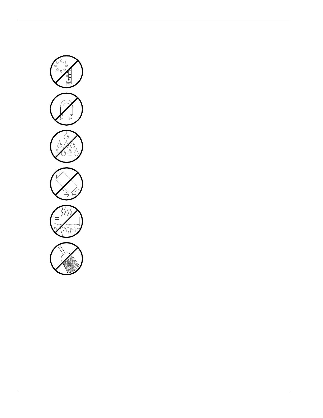
Care and Handling
Use the following guidelines to properly handle and care for your system.
Protect the system from extremely low or high
temperatures. Let the system warm (or cool)
to room temperature before using it.
Keep the system away from magnetic forces.
Keep the system dry. Do not wash the
system with a wet cloth or pour fluid
into it.
Protect the system from being bumped or
dropped.
Check the system for condensation. If
condensation exists, allow it to evaporate
before powering on the system.
Keep the system away from dust, sand,
and dirt.

1
System Overview
Overview
Chassis
System Board Features
Peripheral Devices
System Power
Software Locks via the BIOS Setup

1-2 System Overview
Overview
The server is a modular, multiprocessing server based on the Intel Pentium®
II Xeon chip set. The chip set incorporates a modular scaleable architecture that
integrates a 64-bit bus interface with three Peripheral Component Interconnect
(PCI) buses and an Industry Standard Architecture (ISA) bus. The architecture
supports Symmetrical Multiprocessing (SMP) and a variety of operating
systems. The chassis and system boards are designed to meet the needs of the
server marketplace.
The combination of computing performance, memory capacity, and integrated
I/O provides a high performance environment for many applications including
network servers and multi-user systems. The server is designed for use in
applications where downtime must be minimized. To this end, the server
includes or has the option to include the following.
Power system redundancy; in a system configured with redundant power
supplies, the system will continue to operate with a single power supply
failure.
Self-contained power supply units that can be easily installed or removed
from the back of the chassis.
Hot-swap Ultra2 SCSI-3 hard drive bays accessible from the front of the
chassis; a failed drive can be removed, and a new drive installed without
system power being turned off.
High degree of SCSI hard disk fault tolerance and advanced disk array
management features through the use of RAID (Redundant Array of
Independent Disks) technology.
Hardware monitors (temperature and voltage) and software monitors to
indicate failures.
Easy access to all parts for service.

System Overview 1-3
System Feature Summary
A summary of the system features is included in Table 1-1.
Table 1-1. System Features
Feature Description
Modular board set System is intended for use with a modular board set based on Pentium III
Xeon processor technology; from one to four 500 MHz processors and up
to 8 GB of memory.
Add-in board support System I/O board supports up to 11 add-in boards (ten PCI boards,
including four slots supporting 64-bit PCI boards, and one combination
PCI/ISA board slot).
3 1/2-inch diskette drive 3 1/2-inch diskette drive is externally accessible.
One location for a 3 1/2-inch
removable media device
One externally accessible 3 1/2-inch half-height bay is available for server
expansion.
5 1/4-inch SCSI CD-ROM 5 1/4-inch CD-ROM drive is externally accessible.
Three locations for 5 1/4-
inch removable media
devices
Three externally accessible 5 1/4-inch half-height bays are available for
server expansion (diskette, CD-ROM, and/or tape drives).
12 locations for 3 1/2-inch
Ultra2 Wide SCSI-2 hard
drives
Three hard disk drive cages; each holding up to four 3 1/2-inch hot-
swappable Ultra2 wide SCSI-3 hard drives. Each cage is secured behind
a metal EMI door; drives can be swapped in or out of the system without
powering it down. The array of drives allows easy setup of RAID
applications.
Hot swap-capable
backplane
A hot swap-capable backplane is part of each drive cage assembly for
SCSI hard drives. The backplane is designed for Ultra2 wide SCSI-3
devices that use the industry standard 80-pin Single Connector Attach
(SCA) connector. The backplane consists of a row of four drive
connectors.
Power supply From two to three 560 Watt autoranging power supplies are easily
removed/installed for service. In a three-supply system, the third supply is
redundant.
Software: utilities, setup BIOS Setup and Symbios Configuration Utility. The E
XPRESS
B
UILDER
CD-ROM contains utilities and drivers. The ESMPRO CD-ROM contains
the server management software.
Security
Mechanical: Key lock at the front door. One intrusion sensor for front door
to secure diskette, hard disk, removable media device, power on/off
switch, reset switch, top cover, and left/right panel access. Three power
inter-lock sensors one on each side of the chassis and one on top of the
chassis. BIOS: Password enable.

1-4 System Overview
Expanding the Server as Needs Grow
A typical minimum system configuration may include the following:
Board set consisting of system I/O board, CPU baseboard with one
500 MHz Pentium
III Xeon processor, and one memory board
containing 128MB of memory.
Diskette drive and SCSI CD-ROM drive
Three SCSI hard drive cages with one hard drive and a RAID controller
installed
Integrated Network Interface Controller (NIC)
Two 560 watt power supplies (an optional third power supply provides
redundant power)
Onboard 2 MB video memory
System I/O board has one combination PCA/ISA slot and ten PCI slots
for add-in boards. The system I/O board also has a riser board for
external I/O (serial, parallel, video) interfaces.
Chassis can hold six removable media drives: four 5 1/4-inch half-height
bays with a CD-ROM drive installed in one bay; and two 3 1/2-inch half-
height bays with a diskette drive installed.
As server/client needs grow, you can expand system processor capacity,
memory, drives, option boards, and the number of power supplies.
CPU baseboard has four slots for CPUs, for a configurable range of one,
two, three, or four processors.
Two memory board support 32 DIMM devices for up to a maximum
memory size of 8 GB of memory.
System I/O board has eleven option board slots (ten PCI and one
combination PCI or ISA slot).
Chassis can hold six removable media drives.
Three SCSI hard drive cages support up to 12 hot-swap bays for 3 1/2-
inch Ultra2 wide SCSI-3 hard drives.
Configuration Constraints
The system has four 5 1/4-inch half-height bays accessible from the front. These
bays are convenient for diskette, tape, and CD-ROM drives (removable media).
Because of the EMI generated by hard drives, the increased susceptibility to
ESD, and cooling requirements, hard drives should not be installed in the 5 1/4-
inch half-height bays.
System Overview 1-5
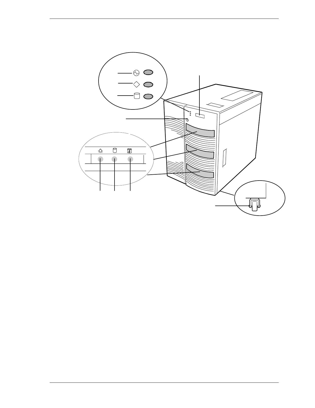
Chassis
Figure 1-1 shows the server front chassis features and controls.
3
FGH
A
B
C
D
E
I
POWER
STATUS
DISK
A
Power LED When green, power is present in system. When off, power is
turned off or power source is disrupted. See Table 1-2 for a
list and description of the system LEDs.
B
Status LED
When green the system is OK. See Table 1-2 for a list and
description of the system LEDs.
C
Disk LED
When green, internal disk drives are being accessed. See
Table 1-2 for a list and description of the system LEDs.
D
Key lock
Secures both front external doors.
E
LCD panel
Displays information about BIOS and system failures (error
and diagnostic information).
F
G
H
Drive present/power on
Drive active
Drive faulty.
Each drive has three LEDs visible above the bay from the
front. See Table 1-3 for a list of SCSI disk drive status LED
indicators.
I
Casters (4) Used when moving the server. Fixed by the caster holders.
Figure 1-1. Front Chassis Features and Controls

1-6 System Overview
Status LED Indicator Descriptions
Table 1-2 lists the system status LED indicators along with a description of each
LED indicator. Table 1-3 lists the disk drive status LED panel indicators along
with a description of each LED indicator. Table 1-4 lists system status abnormal
conditions.
Table 1-2. System Status LED Indicators
LED Status Description Response
Power Off Power OFF None required (normal)
Green Power ON None required (normal)
Amber Sleep Mode Power saving mode (This feature must
be supported by your operating
system).
Status Off Power OFF None required (normal)
Green No alarms None required (normal)
Amber Abnormal condition
(see Table 1-4)
Check condition
Disk Off Not accessing disk drives None required (normal)
Amber Internal disk drive failure Check disk drive status LEDs
Green Accessing disk drives None required (normal)
Table 1-3. Disk Drive Status LED Panel Indicators
LED Status Description Response
Disk Drive
Present
Off Disk drive not present None required (normal)
Green Disk drive present None required (normal)
Disk Drive
Activity
Off Not accessing disk drive None required (normal)
On Accessing disk drive None required (normal)
Disk Drive
Status
Off No alarms None required (normal)
Amber Disk drive failure Replace disk drive.
/