Fluke 190-502 500 MHz ScopeMeter® Test Tool User manual
- Category
- Measuring, testing & control
- Type
- User manual

Fluke 190-104/190-204
ScopeMeter 190 Series II
Service Manual
PN 4822 872 05405
March 2011
© 2011 Fluke Corporation, All rights reserved. Printed in the Netherlands
All product names are trademarks of their respective companies.

PLACING ORDERS AND GETTING ASSISTANCE
To locate an authorized service center, visit us on the World Wide Web:
http://www.fluke.com
or call Fluke using any of the phone numbers listed below:
+1-888-993-5853 in U.S.A. and Canada
+31-40-2675200 in Europe
+1-425-446-5500 from other countries

i
Table of Contents
Chapter Title Page
1 Safety Instructions............................................................................... 1-1
1.1 Introduction.................................................................................................. 1-3
1.2 Safety Precautions........................................................................................ 1-3
1.3 Caution and Warning Statements................................................................. 1-3
1.4 Symbols ....................................................................................................... 1-3
1.5 Impaired Safety............................................................................................ 1-4
1.6 General Safety Information.......................................................................... 1-4
1.7 Safe Handling and Use of Li-ion battery pack............................................. 1-4
2 Characteristics..................................................................................... 2-1
3 List of Replaceable Parts .................................................................... 3-1
3.1 Introduction.................................................................................................. 3-3
3.2 How to Obtain Parts..................................................................................... 3-3
3.3 Final Assembly Parts ................................................................................... 3-4
3.5 Accessories .................................................................................................. 3-7
4 Performance Verification .................................................................... 4-1
4.1 Introduction.................................................................................................. 4-3
4.2 Equipment Required For Verification ......................................................... 4-3
4.3 General Instructions..................................................................................... 4-3
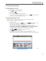
4.4 Operating Instructions.................................................................................. 4-4
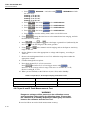
4.4.1 Resetting the Test Tool......................................................................... 4-4
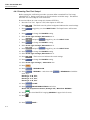
4.4.2 Navigating through menu’s .................................................................. 4-4
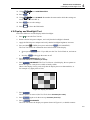
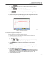
4.4.3 Creating Test Tool Setup1.................................................................... 4-5
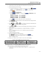
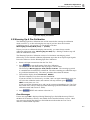
4.5 Display and Backlight Test.......................................................................... 4-6
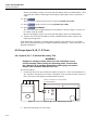
4.6 Scope Input A, B, C, D Tests....................................................................... 4-7
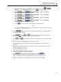
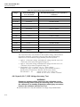
4.6.1 Input A, B, C, D Vertical Accuracy Test.............................................. 4-7
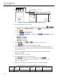
4.6.2 Input A, B, C, D DC Voltage Accuracy Test ....................................... 4-9
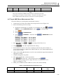
4.6.3 Input A, B, C, D AC Voltage Accuracy Test (LF) ............................... 4-13
4.6.4 Input A, B, C, D AC Coupled Lower Frequency Test ........................ 4-14
4.6.5 Input A and B Peak Measurements Test.............................................. 4-15
4.6.6 Input A, B, C, D Frequency Measurement Accuracy Test.................. 4-16
4.6.7 Input A&B Phase Measurements Test.................................................. 4-18
4.6.8 Time Base Test ..................................................................................... 4-19
4.6.9 Input A Trigger Sensitivity Test........................................................... 4-20
4.6.10 Input A AC Voltage Accuracy (HF) & Bandwidth Test .................... 4-22
4.6.11 Input B Trigger Sensitivity Test ......................................................... 4-23
4.6.12 Input B AC Voltage Accuracy (HF) & Bandwidth Test .................... 4-24
4.6.13 Input C Trigger Sensitivity Test ......................................................... 4-25

Fluke 190-104/190-204
Service Manual
ii
4.6.14 Input C AC Voltage Accuracy (HF) & Bandwidth Test .................... 4-26
4.6.15 Input D Trigger Sensitivity Test......................................................... 4-27
4.6.16 Input D AC Voltage Accuracy (HF) & Bandwidth Test .................... 4-28
4.6.17 Video test using the Video Pattern Generator .................................... 4-29
4.6.18 Video test using SC600 Scope Calibration Option ............................ 4-31
4.7 Probe Calibration Generator Test ................................................................ 4-33
5 Calibration Adjustment ....................................................................... 5-1
5.1 General......................................................................................................... 5-3
5.1.1 Introduction .......................................................................................... 5-3
5.1.2 Calibration number and date................................................................. 5-3
5.1.3 General Instructions.............................................................................. 5-3
5.1.4 Equipment Required For Calibration ................................................... 5-4
5.2 Calibration Procedure Steps......................................................................... 5-4
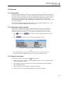
5.3 Starting the Calibration................................................................................ 5-4
5.4 Contrast Calibration Adjustment ................................................................. 5-6
5.5 Warming Up & Pre-Calibration................................................................... 5-7
5.6 Final Calibration .......................................................................................... 5-8
5.6.1 Warm Up Final and ADC Timing ........................................................ 5-8
5.6.2 Input A LF-HF Gain............................................................................. 5-9
5.6.3 Input B LF-HF Gain ............................................................................. 5-10
5.6.4 Input C LF-HF Gain ............................................................................. 5-11
5.6.5 Input D LF-HF Gain............................................................................. 5-12
5.6.6 Input ABCD LF-HF Gain..................................................................... 5-13
5.6.7 Input ABCD Position .......................................................................... 5-15
5.6.8 Input ABCD Volt Gain......................................................................... 5-15
5.6.9 Input ABCD Zero ................................................................................. 5-17
5.7 Save Calibration Data and Exit.................................................................... 5-17
5.8 Probe Calibration ......................................................................................... 5-19
6 Disassembling the Test Tool.............................................................. 6-1
6.1. Introduction................................................................................................. 6-3
6.2. Disassembly & Reassembly Procedures ..................................................... 6-3
6.2.1 Required Tools ..................................................................................... 6-3
6.2.2 Removing the Tilt Stand, Hang Strap, and Side Strap ......................... 6-3
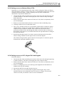
6.2.3 Opening the Test Tool, Removing the Battery Pack ............................ 6-4
6.2.4 Getting access to Top Side of PCA ...................................................... 6-4
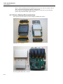
6.2.5 Getting access to Bottom Side of PCA................................................. 6-5
6.2.6 Getting access to LCD, Keypad Foil and Keypad................................ 6-5
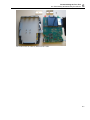
6.2.7 Pictures Showing Disassembly Steps ................................................... 6-6

1-1
Chapter 1
Safety Instructions
Title Page
1.1 Introduction.................................................................................................. 1-3
1.2 Safety Precautions........................................................................................ 1-3
1.3 Caution and Warning Statements................................................................. 1-3
1.4 Symbols ....................................................................................................... 1-3
1.5 Impaired Safety............................................................................................ 1-4
1.6 General Safety Information.......................................................................... 1-4


Safety Instructions
1.1 Introduction 1
1-3
1.1 Introduction
Read these pages carefully before beginning to install and use the Test Tool.
The following paragraphs contain information, cautions and warnings which must be
followed to ensure safe operation and to keep the Test Tool in a safe condition.
Warning
Servicing described in this manual is to be done only by
qualified service personnel. To avoid electrical shock, do not
service the Test Tool unless you are qualified to do so.
1.2 Safety Precautions
For the correct and safe use of this Test Tool it is essential that both operating and service
personnel follow generally accepted safety procedures in addition to the safety
precautions specified in this manual. Specific warning and caution statements, where they
apply, will be found throughout the manual. Where necessary, the warning and caution
statements and/or symbols are marked on the Test Tool.
1.3 Caution and Warning Statements
Caution
Used to indicate correct operating or maintenance procedures
to prevent damage to or destruction of the equipment or other
property.
Warning
Calls attention to a potential danger that requires correct
procedures or practices to prevent personal injury.
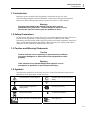
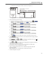
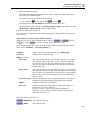
1.4 Symbols
The following symbols are used on the Test Tool, in the Users Manual, in this Service
Information, or on spare parts for this Test Tool.
See explanation in Users Manual
DOUBLE INSULATION (Protection
Class)
Live voltage
Earth Ground
Static sensitive components
(black/yellow).
Li-Ion
Recycling information
Disposal information
Conformité Européenne
Safety Approval Li-ion Battery Pack
Safety Approval

Fluke 190-104/190-204
Service Manual
1-4
1.5 Impaired Safety
Whenever it is likely that safety has been impaired, the Test Tool must be turned off and
disconnected from line power. The matter should then be referred to qualified
technicians. Safety is likely to be impaired if, for example, the Test Tool fails to perform
the intended measurements or shows visible damage.
1.6 General Safety Information
Warning
Removing the Test Tool covers or removing parts, except those
to which access can be gained by hand, is likely to expose live
parts and accessible terminals which can be dangerous to life.
The Test Tool shall be disconnected from all voltage sources before it is opened.
Capacitors inside the Test Tool can hold their charge even if the Test Tool has been
separated from all voltage sources.
When servicing the Test Tool, use only specified replacement parts.
1.7 Safe Handling and Use of Li-ion battery pack
The Test Tool uses a rechargeable Li-ion battery pack. For instructions how to safely
handle and use this battery pack refer to Paragraph “Safety Information” in the Users
Manual of Fluke 190-104 / 190-204 (ScopeMeter 190 Series II).
The Users Manual can be downloaded from Fluke’s website.

2-1
Chapter 2
Characteristics
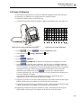
The Fluke 190 Series II ScopeMeter Test Tools have following main characteristics:
- 4 isolated and identical channels, Bandwidth 100 MHz (Model 190-104) or 200 MHz
(Model 190-204), rated 1000 V CAT III, 600 V CAT IV.
- 2.5 GS/s (200 MHz version) or 1.25 GS/s (200 MHz) total sampling speed available for
the channels.
- Intelligent Li-ion Battery Pack with high capacity: 56 Wh (up to 7 Hrs. operating time).
Battery door for quick battery exchange. Optional external battery charger EBC290. Also
with a fully discharged Battery Pack, the instrument will immediately start up when
connected to the Power Adapter BC190.
- Fast isolated USB communication port and isolated port for USB stick (for data
storage).
- Wide 6.4” Color ¼ VGA screen with LED-illumination.
- Probe Calibration output (sq. wave voltage 0 – 1,2 V, frequency 500 Hz).
For the specifications refer to the “Specifications” Chapter in the Fluke
190-104 / 190-204 (ScopeMeter 190 Series II) Users Manual.
Specifications is the last chapter in the Users Manual.
The Users Manual can be downloaded from Fluke’s website.

2-2

3-1
Chapter 3
List of Replaceable Parts
Title Page
3.1 Introduction..................................................................................................3-3
3.2 How to Obtain Parts.....................................................................................3-3
3.3 Final Assembly Parts ...................................................................................3-4
3.5 Accessories ..................................................................................................3-7

Fluke 190-104/190-204
Service Manual
3-2

List of Replaceable Parts
3.1 Introduction 3
3-3
3.1 Introduction
This chapter contains an illustrated list of replaceable parts for the models Fluke 190-
104/190-204 ScopeMeter test tools. Parts are listed by assembly; alphabetized by item
number or reference designator. Each assembly is accompanied by an illustration
showing the location of each part and its item number or reference designator. The parts
list gives the following information:
• Description
• Ordering code
Caution
Electrical components and in particular active components
such as IC’s, transistors and diodes may be damaged by static
discharge.
Handling and servicing static sensitive components and
assemblies should be done only at a static free workstation by
qualified personnel.
3.2 How to Obtain Parts
To locate an authorized service center refer to the second page of this manual (back of the
title page).
In the event that the part ordered has been replaced by a new or improved part, the
replacement will be accompanied by an explanatory note and installation instructions, if
necessary.
To ensure prompt delivery of the correct part, include the following information when
you place an order:
• Instrument model (for example Fluke-190-204), 12 digit instrument code (9444 ...
....), and serial number (15500001). The items are printed on the type plate on the
bottom cover.
• Ordering code
• Description
• Quantity

Fluke 190-104/190-204
Service Manual
3-4
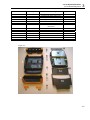
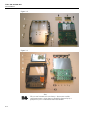
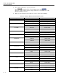
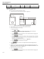
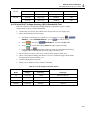
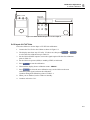
3.3 Final Assembly Parts
See Table 3-1 and Figure 3-1, 3-2 and 3-3 for the Final Assembly parts.
Table 3-1. Final Assembly Parts and Kits
Part or Kit Ordering Code Consists of Following Parts Figure/Item nr
Case Set 3981815
Front case (Excl. lens/decal) 8-3 / 5
Dustseal long (2x) 8-3 / 3
Dustseal short (2x) 8-3 / 4
Case seal 8-3 / 13
Bottom case assy 8-1 / 3
Battery door 8-1 / 14
Quarter turn screw (2x) 8-1 / 15
Adhesive foam (for battery door) --
Standup bracket 8-1 / 14
Li-ion Battery Pack BP291 52 Wh, 10.8 V ---
Lens/decal 190-104 3981826
--- 8-3
Lens/decal 190-204 3981832
--- 8-3
LCD assy Flk-190-II 3981844
LCD module
LCD fixation foam
Flat cable
8-3 / 1
8-3 / 2
8-3 / 7
Topholster (Input
Cover)
3945328 --- 8-1 / 1
Sealing strip (flexible)
around inputs
3945319 --- 8-1 / 11
Mounting Material Set 3981859 Selftapping Screw 10 mm (2x, to fix
input cover)
8-1 / 2
Dowel (6x, to straps) 8-1 / 4
Steel Plate for Lock 8-1 / 5
Selftapping Screw 16.5 mm (4x, to
fix Rear Case)
8-1 / 6
Screw M3x6 (2x, to fix bottom
holster)
8-1 / 8
Selftapping Screw (6x, 10.5 mm to
fix Main PCA Module to Front Case)
8-3 / 12
Side Strap 3945370 Can be fixed on Left or Right side ---
Hang Strap 946769 Can be fixed op Top Side of
Instrument
---
Main PCA Module
(tested)
Only available for Fluke (authorized)
workshops. Requires dedicated tools
to configure.
8-1 / 12,13,
8-2, 8-3 / 8
Bottom Holster Set 3981867 Bottomholster assy 8-1 / 7
Cover for USB 8-1 / 9
Cover for DC adapter power 8-1 / 10
Connector Set 3981871 Probe signal pin (J8010)
Probe ground pin (J8011)
USB-A connector (J8007)
USB-B mini connector (J8003)

List of Replaceable Parts
3.3 Final Assembly Parts 3
3-5
Part or Kit Ordering Code Consists of Following Parts Figure/Item nr
Faston pin battery (5x, X9104-9108)
Cushion (Fits around Faston pin)
Sealing piece USB/Probe (black) 8-3 / 10
Sealing piece DC power (black) 8-3 / 11
Keypad 3942805 8-3/ 6
Keypad Foil 3942810 (Incl. Flat Cable) 8-3 / 9
USB cable 3945381 USB-A to mini-USB-B (for PC
connection)
---
BNC Connector Red 3945031 X1100 ---
BNC Connector Blue 3945046 X1300 ---
BNC Connector Gray 3945054 X1400 ---
BNC Connector Green 3945068 X1200 ---
CD Power Input Socket 215785 X9100 ---
Figure 3-1

Fluke 190-104/190-204
Service Manual
3-6
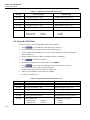
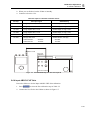
Figure 3-2
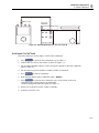
Figure 3-3
Note
Li-Ion
The test tool contains a Li-ion battery. Do not mix with the
solid wastestream. Spent batteries should be disposed of by a
qualified recycler or hazardous materials handler.

List of Replaceable Parts
3.5 Accessories 3
3-7
3.5 Accessories
For a list with accessories refer to the “Maintaining the Test Tool” Chapter in the Fluke
190-104 / 190-204 (ScopeMeter 190 Series II) Users Manual.
The Users Manual can be downloaded from Fluke’s website.

Fluke 190-104/190-204
Service Manual
3-8

4-1
Chapter 4
Performance Verification
Title Page
4.1 Introduction..................................................................................................4-2
4.2 Equipment Required For Verification .........................................................4-2
4.3 General Instructions.....................................................................................4-2
4.4 Operating Instructions..................................................................................4-3
4.4.1 Resetting the Test Tool.........................................................................4-3
4.4.2 Navigating through menu’s ..................................................................4-3
4.4.3 Creating Test Tool Setup1....................................................................4-4
4.5 Display and Backlight Test..........................................................................4-5
4.6 Scope Input A, B, C, D Tests.......................................................................4-6
4.6.1 Input A, B, C, D Vertical Accuracy Test..............................................4-6
4.6.2 Input A, B, C, D DC Voltage Accuracy Test .......................................4-8
4.6.3 Input A, B, C, D AC Voltage Accuracy Test (LF) ...............................4-12
4.6.4 Input A, B, C, D AC Coupled Lower Frequency Test ........................4-13
4.6.5 Input A and B Peak Measurements Test..............................................4-14
4.6.6 Input A, B, C, D Frequency Measurement Accuracy Test..................4-15
4.6.7 Input A&B Phase Measurements Test..................................................4-17
4.6.8 Time Base Test .....................................................................................4-18
4.6.9 Input A Trigger Sensitivity Test...........................................................4-19
4.6.10 Input A AC Voltage Accuracy (HF) & Bandwidth Test ....................4-21
4.6.11 Input B Trigger Sensitivity Test .........................................................4-22
4.6.12 Input B AC Voltage Accuracy (HF) & Bandwidth Test ....................4-23
4.6.13 Input C Trigger Sensitivity Test .........................................................4-24
4.6.14 Input C AC Voltage Accuracy (HF) & Bandwidth Test ....................4-25
4.6.15 Input D Trigger Sensitivity Test.........................................................4-26
4.6.16 Input D AC Voltage Accuracy (HF) & Bandwidth Test ....................4-27
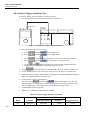
4.6.17 Video test using the Video Pattern Generator ....................................4-28
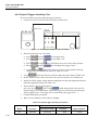
4.6.18 Video test using SC600 Scope Calibration Option ............................4-30
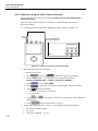
4.7 Probe Calibration Generator Test ................................................................4-32

Fluke 190-104/190-204
Service Information
4-2
4.1 Introduction
Warning
Procedures in this chapter should be performed by qualified
service personnel only. To avoid electrical shock, do not
perform any servicing unless you are qualified to do so.
The Fluke 190-104 (100 MHz) /190-204 (200 MHz) ScopeMeter® Test Tool (referred to
as Test Tool) should be calibrated and in operating condition when you receive it.
The following performance tests are provided to ensure that the Test Tool is in a proper
operating condition. If the Test Tool fails any of the performance tests, calibration
adjustment (see Chapter 5) and/or repair in a Fluke (authorized) workshop is necessary.
The Performance Verification Procedure is based on the specifications, listed in
Chapter 2 of this Service Information. The values given here are valid for ambient
temperatures between 18 °C and 28 °C.
The Performance Verification Procedure is a quick way to check most of the Test Tool’s
specifications. Because of the highly integrated design of the Test Tool, it is not always
necessary to check all features separately.
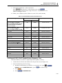
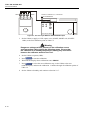
4.2 Equipment Required For Verification
The primary source instrument used in the verification procedures is the Fluke 5500A. If
a 5500A is not available, you can substitute another calibrator as long as it meets the
minimum test requirements.
• Fluke 5500A Multi Product Calibrator, including SC300 or SC600 Oscilloscope
Calibration Option.
• 50Ω Coax Cables (4x): use Fluke PM9091 (1.5m, 3 pcs.) and PM9092 (0.5m, 3 pcs.).
• Male BNC to Dual Female BNC adapter (1x), Fluke PM9093/001
• 50Ω feed through termination, Fluke PM9585.
• Dual Banana Plug to Female BNC Adapter (1x), Fluke PM9081/001.
• Dual Banana Jack to Male BNC Adapter (1x), Fluke PM9082/001.
• TV Signal Generator, Philips PM5418, NOT required if SC600 Oscilloscope
Calibration Option is used.
• 75Ω Coax cable (1x), Fluke PM9075.
• 75Ω Feed through termination (1x), ITT-Pomona model 4119-75.
• 10:1 Attenuator Probes as supplied with Test Tool.
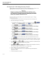
4.3 General Instructions
Follow these general instructions for all tests:
• For all tests, power the Test Tool with the BC190 power adapter/battery charger.
The battery pack must be installed.
• Allow the 5500A to satisfy its specified warm-up period.
• For each test point , wait for the 5500A to settle.
• Allow the Test Tool a minimum of 30 minutes to warm up.
• One division on the LCD consists of 25 pixels (1 pixel = 0.04 division).
Page is loading ...
Page is loading ...
Page is loading ...
Page is loading ...
Page is loading ...
Page is loading ...
Page is loading ...
Page is loading ...
Page is loading ...
Page is loading ...
Page is loading ...
Page is loading ...
Page is loading ...
Page is loading ...
Page is loading ...
Page is loading ...
Page is loading ...
Page is loading ...
Page is loading ...
Page is loading ...
Page is loading ...
Page is loading ...
Page is loading ...
Page is loading ...
Page is loading ...
Page is loading ...
Page is loading ...
Page is loading ...
Page is loading ...
Page is loading ...
Page is loading ...
Page is loading ...
Page is loading ...
Page is loading ...
Page is loading ...
Page is loading ...
Page is loading ...
Page is loading ...
Page is loading ...
Page is loading ...
Page is loading ...
Page is loading ...
Page is loading ...
Page is loading ...
Page is loading ...
Page is loading ...
Page is loading ...
Page is loading ...
Page is loading ...
Page is loading ...
Page is loading ...
Page is loading ...
Page is loading ...
Page is loading ...
Page is loading ...
Page is loading ...
Page is loading ...
Page is loading ...
Page is loading ...
Page is loading ...
-
 1
1
-
 2
2
-
 3
3
-
 4
4
-
 5
5
-
 6
6
-
 7
7
-
 8
8
-
 9
9
-
 10
10
-
 11
11
-
 12
12
-
 13
13
-
 14
14
-
 15
15
-
 16
16
-
 17
17
-
 18
18
-
 19
19
-
 20
20
-
 21
21
-
 22
22
-
 23
23
-
 24
24
-
 25
25
-
 26
26
-
 27
27
-
 28
28
-
 29
29
-
 30
30
-
 31
31
-
 32
32
-
 33
33
-
 34
34
-
 35
35
-
 36
36
-
 37
37
-
 38
38
-
 39
39
-
 40
40
-
 41
41
-
 42
42
-
 43
43
-
 44
44
-
 45
45
-
 46
46
-
 47
47
-
 48
48
-
 49
49
-
 50
50
-
 51
51
-
 52
52
-
 53
53
-
 54
54
-
 55
55
-
 56
56
-
 57
57
-
 58
58
-
 59
59
-
 60
60
-
 61
61
-
 62
62
-
 63
63
-
 64
64
-
 65
65
-
 66
66
-
 67
67
-
 68
68
-
 69
69
-
 70
70
-
 71
71
-
 72
72
-
 73
73
-
 74
74
-
 75
75
-
 76
76
-
 77
77
-
 78
78
-
 79
79
-
 80
80


Fluke 190-502 500 MHz ScopeMeter® Test Tool User manual
- Category
- Measuring, testing & control
- Type
- User manual
Ask a question and I''ll find the answer in the document
Finding information in a document is now easier with AI
Related papers
-
Fluke ScopeMeter®-testverktøy i 190 II-serien User manual
-
Fluke FL190-204 Owner's manual
-
Fluke 500-serien batterianalysatorer User manual
-
Fluke Oscilloscopi portatili industriali ScopeMeter® serie 120B User manual
-
-
-
-
Fluke Penganalisis Penggerak Motor MDA-510 dan MDA-550 User manual
-
-
Other documents
-
Valeo SC600 Indien Operating Instructions Manual
-
Extech Instruments SC600 User manual
-
Fluke Calibration 5720A Operating instructions
-
-
Tektronix THS3014 Owner's manual
-
-
 Setra Systems MicroCal™ Pressure Transducer Calibrator Operating instructions
-
Milwaukee CALIBRATION 2238-20 Specification
-
-
Tektronix TPS2014B User manual
