Page is loading ...


973-SF6 E V3.0R i
Table of Contents
TABLE OF CONTENTS ...................................................................................... I
GENERAL .......................................................................................................... 1
SHORT DESCRIPTION ...................................................................................... 3
OPERATION....................................................................................................... 5
Front Panel without SO2 Option ................................................................................................. 5
Front Panel with SO2 Option ...................................................................................................... 5
Back Panel without SO2 Option ................................................................................................. 9
Back Panel with SO2 Option ...................................................................................................... 9
INITIAL SETUP ................................................................................................ 11
Preparation ............................................................................................................................... 11
Electrical Connection ............................................................................................................... 11
Connection of the Serial Interface ............................................................................................ 11
SF6 Gas Connection ................................................................................................................ 12
Evacuate the Sampling Tube ................................................................................................... 13
Evacuation of the Internal Cylinder .......................................................................................... 14
SF6 Gas Connection to the Compartment ............................................................................... 15
MEASUREMENT OPTIONS ............................................................................. 17
Navigating the Menus .............................................................................................................. 17
MEASUREMENT .............................................................................................. 19
Measurement without SO2 Option ........................................................................................... 19
Termination of Measurement ................................................................................................... 20
Measurement with SO2 Option................................................................................................. 21
Termination of Measurement ................................................................................................... 22
Measuring Range Limitations .................................................................................................. 23
Alarm Messages ...................................................................................................................... 23
Measurement Aborted ............................................................................................................. 24
Measurement of Air or Nitrogen (N2) ....................................................................................... 24
DATA COLLECTION IN EXCEL ...................................................................... 25
RS-232 – USB Converter Installation ...................................................................................... 25
Data Collection over RS-232 with the Excel Protocol .............................................................. 26
SO2 MODULE ................................................................................................... 29
TEST FUNCTIONS ........................................................................................... 31
Ice Test .................................................................................................................................... 31

ii 973-SF6 E V3.0R
ADDITIONAL FUNCTIONS .............................................................................. 35
Selection of the Indicated Parameters ..................................................................................... 35
Selection of Units ..................................................................................................................... 36
Changing Color ........................................................................................................................ 37
Storage of the Actual Settings ................................................................................................. 38
Restore Color Settings and Baud Rate .................................................................................... 39
MAINTENANCE ............................................................................................... 41
Touch Screen Calibration ........................................................................................................ 41
Mirror Cleaning ......................................................................................................................... 42
Exterior Cleaning ...................................................................................................................... 43
SPECIFICATIONS ............................................................................................ 45

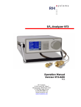
973-SF6 E V3.0R 1
General
This manual explains the function of the 973- SF6 Analyzer with and without the SO2 option.
Throughout this manual the instrument will be called 973.
This manual refers to instrument software versions 110525a and higher.
Should the 973 be used in any other way than that described in this
user’s manual, or outside the limits described, the built-in safety pro-
tection of the instrument may be compromised.
Vol SF6 %
All descriptions in bold italic are related to the text on the front panel,
the display and the back panel of the 973.
If you wish to use the instrument as quickly as possible, we recommend reading the chapters
Initial Setup (page 11) and Measurement (page 19). Standard use of the instrument is ex-
plained in these two chapters.


973-SF6 E V3.0R 3
Short Description
Reliable Measurements in SF6
The 973 was specifically designed for measurement of humidity, SF6 purity and SO2 concentra-
tion in gas insulated switchgear systems. Humidity measurement data is displayed in ppmv,
ppmw and Dew/Frost Point. SF6 purity measurement is displayed directly in % Volume SF6. Both
the humidity and purity measurements utilize accurate and reliable condensation techniques.
SO2 concentration is measured with an electrochemical cell with results displayed in ppmv.
Gas Recovery and Pressure Measurement
The 973 is equipped with a gas recovery system that stores the sampled gas during the meas-
urement process in its internal storage tank. After completion of the measurement, the stored
gas is automatically pumped back into the original compartment or into another vessel. The
compartment pressure is also measured.
Easy, Automated Measurement
The 973 is equipped with a user configurable full color active matrix LCD with integrated touch
screen. The 973 may be configured for measurement of Humidity and % Volume SF6 with either
automatic or manually initiated Pump Back. Using the bi-directional RS-232 communications
port, all measurement data may be easily transferred to a computer.
Calibration
Users can easily check the 973 calibration at any time using the built-in Ice Test function,
providing instant verification of system accuracy and integrity.
Connect and Go
The system is supplied ready for immediate use.
973-SF6 with Standard Accessories
Transport Case
6m Stainless Steel armored PTFE tubing
DILO coupling DN20 and DN8
3 m RS-232 cable incl. USB adapter with USB cable
3 m power cable
Operation Manual
CD-ROM


973-SF6 E V3.0R 5
Operation
Front Panel without SO2 Option
Front Panel with SO2 Option
Touch Screen
Data Lines
Menu Keys
Measuring Head
Keypad
Status of Measurement
Fixed Function Keys
Internal
Tank Capacity

6 973-SF6 E V3.0R
LCD Display with Touch Panel
The 973 utilizes a full color active matrix liquid crystal display with an integral touch panel. It has
a high contrast ratio and a wide viewing angle for easy readability. Data is displayed in large,
easy to read fonts. Using the on screen function and menu keys, you can easily configure each
line of the display and navigate the menus.
Versions equipped with the SO2 option will have alternative display and data line formats.
Please refer to page 21 for further information on the measurement of SO2 concentration.
Data Lines
The first four lines of the display are for numeric representation of the measured data. We refer
to those first four lines as Data Lines. Numeric data lines contain the value to the left, with the
parameter description and units to the right. The displayed parameters and units can be
changed, but after a restart of the instrument, the values will be reset to the stored standard
configuration.
Data Line 1
This line displays the measured Dew/Frost Point.
The unit is °C related to atmospheric pressure.
In the standard configuration, instruments equipped
with the SO2 option show the SO2 concentration
expressed in ppmv. The standard SO2 configuration
is shown on the second display.
Data Line 2
This line displays the humidity content in either
ppmv (parts per million by volume) or ppmw (parts
per million by weight). This ppmv unit is pressure
independent.
Data Line 3
This line displays the purity in % Volume SF6.
Data Line 4
This line indicates the current pressure of the gas
compartment. The unit is kilo Pascal absolute pres-
sure.
The data lines indicating the measured Humidity and SO2 concentrations as well as
the % Volume SF6 will only be displayed after completion of the measurement. Dur-
ing the measurement only the current gas pressure of the measured compartment
is indicated.

973-SF6 E V3.0R 7
Fixed Function Keys and Status Line
Without SO2 Option
With SO2 Option
The bottom line of the display contains two fixed
function keys.The measurement process is started
by pressing the Start button. With the Pump button,
pump back of stored gas in the internal cylinder can
be activated manually. These function keys are not
changeable and are always available. Additionally
this line contains the status indication, which indi-
cates the current operation mode. The level indica-
tor of the internal tank indicates the current storage
capacity. A 973 without the SO2 option will display
an X next to SO2 to indicate that the measurement
of SO2 concentration is not available.
Menu Keys
To the right side of the display is a column of menu
keys. Each of these keys changes function as
needed.
Notice that the bottom key in this column is different
from the rest. The bottom key is used to cycle the
upper keys through the various menu options. The
text on the bottom key changes to indicate the cur-
rently selected menu option. The text of the upper
keys change based on the functions available in the
menu.
Keypad
The keypad is used for entering data into the 973.
For normal operation it is rarely used.
Use the
bottom
key to
change
menus.

8 973-SF6 E V3.0R
Carrying Handle
To adjust the position of the carrying handle, press
the buttons on both sides to unlock it before rotat-
ing. Release the buttons when the desired position
is found.

973-SF6 E V3.0R 9
Back Panel without SO2 Option
Back Panel with SO2 Option
Fan
Gas Inlet
Quick Coupling
RS-232
Serial Interface
Power Socket
with Main Switch
Optional SO2 Sensor
with Calibration Date
and Replacement Date

10 973-SF6 E V3.0R
Power Connection
The AC power cord is connected to the power socket on the instrument back panel. The power
socket also includes the power switch. The power supply voltage is 100-120 VAC /
200-240 VAC at 50 to 60Hz. The power supply is internally fused and will automatically switch
off in case of an overload. To restart the power supply, the instrument main switch must be
switched to 0 and I again.
SO2 Module
When fitted, the SO2 module is mounted to the back panel of the 973 which allows the SO2 sen-
sor to be easily replaced by the user. The sensor has to be replaced every two years. The cali-
bration and replacement dates are indicated on the SO2 Module.
Gas Inlet Quick Coupling
The sampling line is connected to the sample gas inlet. If the instrument is not in use the inlet
should be protected with the blue cover.
RS-232 Serial Interface Connector
The RS-232 connector is used when connecting the 973 to a computer. Use the supplied 9 pin
1:1 cable to connect the 973 to a desktop or laptop computer. This cable has a male connector
on one end and a female connector on the other end. It is most often referred to as a serial ex-
tension cable.
Fan
When the 973 is switched on, the cooling fan always runs independent of the ambient and in-
strument temperatures.

973-SF6 E V3.0R 11
Initial Setup
Preparation
The 973 needs a source of normal AC power. The label on the back panel indicates the ac-
ceptable input voltage range. The instrument has been designed to work with a power range
between 100-120 VAC / 200-240 VAC at 50 to 60 Hz. This normally covers all usual AC line
voltages.
Electrical Connection
The power socket and the 973 main power switch are on the
back panel of the instrument. Use the provided power cable
to connect the instrument to the AC power.
Start the instrument by turning on the power switch. The dis-
play of the 973 comes up immediately following the proces-
sor’s boot phase. The boot phase may take several seconds
to complete.
Connection of the Serial Interface
If you intend to transfer the measured data to a computer,
connect the serial cable between the instruement and the
computer.

12 973-SF6 E V3.0R
If your computer is equipped with a USB interface, you can
use the provided RS-232/USB converter. You will find the
drivers on the CD. The installation and data collection will be
explained in the chapter ‘Data Collection in Excel’ on
page25.
SF6 Gas Connection
The quick coupling on the instrument side of the sampling
tube must be connected to the SAMPLE GAS inlet.
Note:
To prevent contamination, the blue cover caps of the instru-
ment and sampling tube should always be installed when the
instrument is not in use.
The standard accessories of the 973 include a DN8 and a
DN20 DILO coupling.

973-SF6 E V3.0R 13
Evacuate the Sampling Tube
The sampling tube must be evacuated before the first initial measurement is started. Once ini-
tially evacuated, there is no need to re-evacuate the hose, even when moving the connection to
the next compartment.
Make sure that a DILO coupling DN8 or DN20 is properly
installed on the sampling tube, but do not connect the DILO
coupling to anything else at this time. Since the DILO cou-
plings are self-sealing, the sampling tube is sealed.
Ensure that the other end of the sampling tube is properly
connected to the 973.
Press the lower right key in order to select the Control Set-
up menu. Control Setup appears on the key, while on the
upper keys the available menu options are indicated.
Press the Evacuate Hose key.
With the sampling tube correctly connected, press the Ok
key in order to start the evacuation process.
After the evacuation has started, the next window indicates
the decreasing pressure of the sampling gas tube while
evacuating.
After reaching the set residual pressure of 20 kPa, the evac-
uation process is stopped automatically and the window
closes. The instrument and the sampling tube are now ready
for measurement.
By pressing the Cancel key during evacuation, the process
can be manually stopped.

14 973-SF6 E V3.0R
Evacuation of the Internal Cylinder
If the content of the internal cylinder is unknown, or contaminated SF6 gas is in the storage tank,
the internal storage cylinder can be evacuated.
Press the Evacuate Internal Cylinder key in the Control
Setup menu.
The dialogue box requests you to remove the sampling
gas tube or connect an SF6 reclaimer to the 973.
Disconnect the quick coupling from the SAMPLE GAS inlet
or connect the instrument to an SF6 reclaimer.
Press the Ok button to start the internal cylinder evacua-
tion.
The dialogue box indicates the current internal cylinder
pressure during evacuation. After evacuating below 20 kPa
residual pressure, the internal pump automatically stops.
The evacuation process can be stopped by pressing the
Ok button.
If the 973 is connected to an external reclaimer, evacuation
can be continued with the reclaimer until the desired resid-
ual pressure is reached. By pressing the Ok button, the
evacuation process can be stopped.

973-SF6 E V3.0R 15
SF6 Gas Connection to the Compartment
If the sampling tube was properly evacuated before the first
measurement, it is now ready to connect to the gas com-
partment. When moving the connection from compartment to
compartment, there is no need to re-evacuate.
Remove the dust caps from fittings, check both threads are
clean, and carefully screw on the fitting ensuring a good seal
is made.

/