Page is loading ...

Ceiling Fan Installation Manual
UHP9350, UHP9351, UHP9352

Date Purchased
Sto re Purch as ed
Model No.
Serial No .
Vendor No.
UPC
Limited Lifetime Warranty
Progress Lighting fan motors are warranted to the original purchaser to be free of electrical and/or mechanical defects for so
long as the original purchaser owns the fan. Pull chain switches, reverse switches, capacitors and metal finishes are warranted to
be free from defects in materials or workmanship for a period of 1 year from the date of purchase. Warping of wooden or plastic
blades is not covered by this warranty nor is corrosion and/or deterioration of any finishes for fans installed within ten miles of
any sea coast. Extended warranties for ENERGY STAR® qualified products may apply.
Progress Lighting ceiling fans with built-in LED light sources, when properly installed and under normal conditions of use, are
warranted to be free from defects in material and workmanship which cause the light sources to fail to operate in accordance
with the specifications for (i) five (5) years from the date of purchase on the LED Light modules and electrical components for
fans used in single family residences, and (ii) three (3) years from the date of purchase on the LED Light modules and electrical
components for fans used in multi-family or commercial applications. LED bulbs supplied by Progress Lighting carry no
warranty other than manufacturer’s warranty. Non-LED bulbs carry no warranty.
With proof of purchase, the original purchaser may return the defective fan to the place of purchase during the first 30 days for
replacement. After 30 days, the original purchaser MUST contact Progress Lighting at (864) 678-1000 for repair or replacement
which shall be determined in Progress Lighting’s sole discretion and shall be purchaser’s sole and exclusive remedy.
Labor and Shipping Excluded. This warranty does not cover any costs or fees associated with the labor (including, but not
limited to, electrician’s fees) required to install, remove, or replace a fan or any fan parts.
This warranty shall not apply to any loss or damage resulting from (i) normal wear and tear or alteration, misuse, abuse or
neglect, or (ii) improper installation, operation, repair or maintenance by original purchaser or a third party, including without
limitation improper voltage supply or power surge, use of improper parts or accessories, unauthorized repair (made or
attempted) or failure to provide maintenance to the fan.
THE FOREGOING WARRANTIES STATE PROGRESS LIGHTING’S ENTIRE WARRANTY OBLIGATION AND
ORIGINAL PURCHASER’S SOLE AND EXCLUSIVE REMEDY RELATED TO SUCH PRODUCTS. PROGRESS
LIGHTING IS NOT RESPONSIBLE FOR DAMAGES (INCLUDING INDIRECT, SPECIAL, INCIDENTIAL OR
CONSEQUENTIAL), DUE TO PRODUCT FAILURE, WHETHER ARISING OUT OF BREACH OF WARRANTY,
BREACH OF CONTRACT, OR OTHERWISE. THIS WARRANTY IS GIVEN IN LIEU OF ALL OTHER WARRANTIES,
WHETHER EXPRESSED OR IMPLIED, INCLUDING THOSE OF MERCHANTABILITY, FITNESS FOR A PARTICULAR
PURPOSE OR NONINFRINGEMENT.
Some states do not allow limitations on how long an implied warranty lasts or the exclusion or limitations of incidental or
consequential damages, so the above limitations and exclusions may not apply to you. This warranty gives you specific rights
and you may have other rights which vary from state to state.

Table of Contents
Safety Rules.....................................................................................................................................................................................
Unpacking Your Fan .......................................................................................................................................................................
Installing Your Fan .........................................................................................................................................................................
Operating Your Transmitter ............................................................................................................................................................
Care of Your Fan ...........................................................................................................................................................................
Troubleshooting ............................................................................................................................................................................
Specifications ................................................................................................................................................................................
1.
2.
3.
9.
10.
11.
12.

1. Safety Rules
To reduce the risk of electric shock, ensure electricity has been turned off
at the circuit breaker or fuse box before beginning.
1.
All wiring must be in accordance with the National Electrical Code
“ANSI/NFPA 70-1999” and local electrical codes. Electrical installation
should be performed by a qualified licensed electrician.
2.
The outlet box and support structure must be securely mounted and
capable of reliably supporting a minimum of 35 lbs (15.9 kg) or less. Use
only UL-listed outlet boxes marked “FOR FAN SUPPORT.”
3.
The fan must be mounted with a minimum of 7 ft. (2.1m) clearance from
the trailing edge of the blades to the floor.
4.
Avoid placing objects in the path of the blades.
5.
To avoid personal injury or damage to the fan and other items, be
cautious when working around or cleaning the fan.
6.
Do not use water or detergents when cleaning the fan or fan blades. A dry
dust cloth or lightly dampened cloth will be suitable for most cleaning.
7.
After making electrical connections, spliced conductors should be turned
upward and pushed carefully up into the outlet box. The wires should be
spread apart with the grounded conductor and the equipment-grounding
conductor on one side of the outlet box and ungrounded conductor on the
other side of the outlet box.
8.
All set screws must be checked and retightened where necessary before
installation.
9.
This device complies with Part 15 of the FCC Rules. Operation is subject
to the following two conditions:
(1) This device may not cause harmful interference, and (2) this device
must accept any interference received, including interference that may
cause undesired operation. Please note that changes or modifications not
expressly approved by the party responsible for compliance could void
the user's authority to operate the equipment.
Note:
This equipment has been tested and found to comply with the
limits for Class B digital device, pursuant to part 15 of the FCC Rules.
These limits are designed to provide reasonable protection against
harmful interference in a residential installation.This equipment
generates, uses and can radiate radio frequency energy and, if not
installed and used in accordance with the instructions, may cause harmful
interference to radio or television reception, which can be determined by
turning the equipment off and on, the user is encouraged to try to correct
the interference by one or more of the following measure.
- Reorient or relocate the receiving antenna.
- Increase the separation between the equipment and the receiver.
- Connect the equipment into an outlet on a circuit different from that to
which the receiver is connected. Consult the dealer or an experienced
radio/TV technician for help.
10.
WARNING
TO REDUCE THE RISK OF PERSONALL INJURY, DO NOT BEND THE BLADE ARMS (ALSO REFERRED TO AS
FLANGES), WHEN INSTALLING THE BRACKETS, BALANCING THE BLADES OR CLEANING THE FAN. DO
NOT INSERT FOREIGN OBJECTS IN – BETWEEN ROTATING FAN BLADES.
NOTE
READ AND SAVE THESE INSTRUCTIONS
WARNING
TO REDUCE THE RISK OF FIRE, ELECTRIC SHOCK, OR OTHER PERSONAL INJURY, MOUNT FAN ONLY ON AN
OUTLET BOX OR SUPPORTING SYSTEM MARKED ACCEPTABLE FOR FAN SUPPORT OF 35 LBS (15.9 KG) OR LESS
AND USE MOUNTING SCREWS PROVIDED WITH THE OUTLET BOX. MOST OUTLET BOXES COMMONLY USED FOR
THE SUPPORT OF LIGHTING FIXTURES ARE NOT ACCEPTABLE FOR FAN SUPPORT AND MAY NEED TO BE
REPLACED. CONSULT A QUALIFIED ELECTRICIAN IF IN DOUBT.

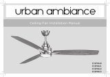
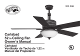
Unpack your fan and check the contents. You should have the following items:
Unpacking Your Fan 2.
14. Loose parts bag containing:
a. Blade attachment hardware
(7 screws, 7 washers)
d. Cable hardware
(1pc per item)
e. Mounting hardware
Wire nuts (7)
b. Metal bracket (3)
c. Blade down-screw (7)
1. Fan blades (3)
2. Hanger bracket
3. Ball/downrod assembly
4. Canopy
5. Decorative cover
6.
Coupling cover
7.
Fan motor assembly
8.
Switch housing
9. LED light kit
10. Shatterproof Cover
11. Receiver with 6 wire nuts
12. Transmitter incl. holder + 2 mounting screws
13. 3V battery
14
a b c
d e
1
2
3
4
7
6
8
9
10
11
12 13
5
5
6
12
0
3
4

Tools Required
Phillips screw driver, straight slot screw driver,
adjustable wrench, step ladder, and wire cutters.
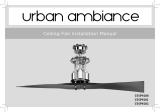
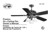
Mounting Options
If there isn't an existing UL listed mounting box,
then read the following instructions. Disconnect
the power by removing fuses or turning off
circuit breakers.
Secure the outlet box directly to the building
structure. Use appropriate fasteners and building
materials. The outlet box and its support must be
able to fully support the moving weight of the
fan (at least 35 lbs). Do not use plastic outlet
boxes.
Figure 4
Figure 3
Figure 1
Figure 2
Outlet box
Outlet box Outlet box
Note: You may need a longer downrod to
maintain proper blade clearance when installing
on a steep, sloped ceiling.
To hang your fan where there is an existing
fixture but no ceiling joist, you may need an
installation hanger bar as shown in Figure 4
(available at your Progress Lighting Retailer).
3. Installing Your Fan
WARNING
TO REDUCE THE RISK OF FIRE, ELECTRIC
SHOCK, OR OTHER PERSONAL INJURY,
MOUNT FAN ONLY TO AN OUTLET BOX
MARKED ACCEPTABLE FOR FAN SUPPORT
AND USE THE MOUNTING SCREWS
PROVIDED WITH THE OUTLET BOX. OUTLET
BOXES COMMONLY USED FOR THE
SUPPORT OF LIGHTING FIXTURES MAY NOT
BE ACCEPTABLE FOR FAN SUPPORT AND
MAY NEED TO BE REPLACED. CONSULT A
QUALIFIED ELECTRICIAN IF IN DOUBT.
Angled ceiling
maximum
24 Degrees
Recessed
outlet box
Provide strong support
Ceiling
hanger
bracket

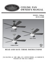
4.
Hanging the Fan
REMEMBER to turn off the power. Follow
the steps below to hang your fan properly:
Step 1. Pass the 120-volt supply wires
through the center hole in the ceiling hanger
bracket as shown in Fig. 5.
Step 2. Secure the hanger bracket to the
ceiling outlet box with the screws and
washers provided with your outlet box.
Figure 5
Ceiling
hanger
bracket
120V Wires
Washers
Mounting screws
(supplied with
electrical box)
UL Listed
electrical
box

5.
Step 2. Attach the blade down—screws and the
metal bracket (b) as shown in figures 7 and 7a.
Make sure that each metal bracket is attached to
two different blades as seen in figure 7a. Start a
screw into the blade, do not tighten. Repeat for
the remaining screws. Repeat these steps for the
remaining screws and metal brackets.
Figure 7
The bottom of the motor
Blade down-
screw
Step 3. Remove the hanger pin, lock pin and
set screws from the top of the motor
assembly. (Fig. 8)
Step 4. Route the wires exiting from the top
of the fan motor through the coupling cover,
canopy cover and canopy and then through
the ball / downrod. (Fig. 8)
Step 5.
Align the holes at the bottom of the
downrod with the holes in the collar on top of the
motor housing (Fig. 8). Carefully insert the hanger
pin through the holes in the collar and downrod. Be
careful not to jam the pin against the wiring inside
the downrod. Insert the locking pin through the hole
near the end of the hanger pin until it snaps into its
locked position, and tighten set screws as noted in
the circle inset of Fig 8. Cut off excess fixture wires
leaving approximately 6 to 9 inches above top of
hanger ball/downrod assembly.
Figure 8
Downrod
Canopy
Canopy
cover
Coupling
cover
Lock pin
Hanger pin
Set screws
Blade
Fan Motor Assembly
Installing the Blades
Step 1. Attach the blades to the fan motor
assembly using blade up-screws as shown in
Figure 6. Start a screw into the blade, do not
tighten. Repeat for the remaining screw and
washer. Repeat these steps for the remaining
blades.
Figure 6
Blade up - screw
The top of
the motor
Fan motor assembly
WARNING
FAILURE TO PROPERLY INSTALL
LOCKING PIN AS NOTED IN STEP 5
COULD RESULT IN FAN LOOSENING AND
POSSIBLY FALLING.
Figure 7a
Metal
Bracket

Figure 9
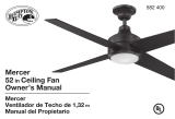
1.
2.
(Figure 10) Place the EMI filter into the ceiling
box before installing the receiver into the bracket.
Insert the receiver into the mounting bracket with
the flat side of the receiver facing the ceiling.
(Figure 11) Motor to receiver electrical
connections: Connect the grey wire from the
fan to grey wire from the receiver. Connect
the red wire from the fan to the red wire from
the receiver. Connect the yellow wire from the
fan to the yellow wire from the receiver. Connect
the blue wire from the fan to the blue wire from
the receiver. Connect the white wire from the fan
to the white wire from the receiver.
nuts provided.
Secure the
wire
connections
with the plastic wire connecting
Making the Electrical
Connections
If
Connect green wires from EMI Filter and related
parts according to the wiring diagram as shown in
Figure 11, make sure EMI Filter is properly seated
in outlet box.
you feel you do not have enough electrical
wiring knowledge or experience, have your fan
installed by a licensed electrician.
TO AVOID POSSIBLE ELECTRICAL SHOCK, BE
SURE ELECTRICITY IS TURNED OFF AT THE
MAIN FUSE BOX BEFORE WIRING.
NOTE
NOTE
FAN MUST BE INSTALLED AT A MAXIMUM
DISTANCE OF 20 FEET FROM THE
TRANSMITTING UNIT FOR PROPER
SIGNAL TRANSMISSION BETWEEN THE
TRANSMITTING UNIT AND THE FAN'S
RECEIVING UNIT.
6.
o the hangerStep 4. Place the downrod ball int
b
ball is seated in the groove on the hanger bracket.
Drive a wood screw and washers into the side of
the brace that holds the outlet box. Leave 3mm
(1/8”) of space between the support brace and the
washer. Insert the safety cable through the hanger
bracket and one of the holes in the outlet box into
the ceiling. Adjust the length of the safety cable to
reach the screw and washers by pulling the extra
cable through the cable clamp until the overall
length is correct, put the end of the cable back
through the cable clamp,forming a loop at the end
of the cable. Tighten the cable clamp securely.
Now, put the loop in the end of the safety cable
over the wood screw and under the washer.
Tighten the wood screw securely.(Figure 9)
racket socket (Fig.9). Make sure the hanger
Figure 10
Hanger
bracket
EMI Filter
Figure 11
Hanger
bracket
Canopy
Downrod
ball
Safety cable
Wood
screw
Washer
Spring washer
Blue
Blue
White
White
Ground wire
Ground wire
AC IN L(Black)
AC IN N(White)
Ground wire
Gray
Gray
Yellow
Red
Yellow
Red
Ground wire
Ground wire
Ground wire

3. (Figure 11) Receiver to house supply wires
electrical connections: Connect the black (hot)
wire from the ceiling to the black wire marked
"AC in L" from the receiver. Connect the white
(neutral) wire from the ceiling to the white wire
marked "AC in N" from the receiver. Secure
the wire connections with the plastic wire
connecting nuts provided.
4. (Figure 11) If your outlet box has a ground
wire (green or bare copper) connect it to the fan
ground wires; otherwise connect the hanging
bracket ground wire to the mounting bracket.
Secure the wire connection with a plastic nut
provided. After connecting the wires spread
them apart so that the green and white wires are
on one side of the outlet box and black and blue
wires are on the other side. Carefully tuck the
wire connections up into the outlet box.
7.
Finishing the Installation
Step 1. Tuck connections neatly into ceiling
outlet box.
Step 2. Slide the canopy up to mounting bracket
and place the key hole on the canopy over the
screw on the mounting bracket, turn canopy until
it locks in place at the narrow section of the key
holes. (Fig. 12)
Step 3. Align the circular hole on canopy with the
remaining hole on the mounting bracket, secure
by tightening the two set screws. Note: Adjust the
canopy screws as necessary until the canopy and
canopy cover are snug.
Installing the Switch Housing
Remove the screw marked with a dot label which
preinstalled on mounting plate and keep for later
use. Loosen the other two (do not remove). Place
the two slot holes on the switch housing over the
2 screws previously loosened from the mounting
plate. Rotate the switch housing until it locks in
place at the narrow end of the key holes. Securely
by tightening the 2 screws previously loosened
and the one previously removed (Fig.13).
WARNING
Make sure the notch on the hanging bracket
properly sits in the groove in the hanger ball
before attaching the canopy to the bracket by
turning the housing until it drops into place.
Figure 12
Decorative
cover
Canopy
Canopy
Figure 13

8.
Blade Balancing
All blades are grouped by weight.The fan may
wobble even though the blades are weighed
equally.
The following procedure should correct most fan
wobbling problems. Check after each step.
1. Check that all blade and blade arm screws are
secure.
2. Most fan wobbling problems are caused when
blade levels are unequal. Check this level by
selecting a point on the ceiling above the tip of
one of the blades. Measure this distance as
shown in Figure 14. Rotate the fan until the
next blade is positioned for measurement.
Repeat for each blade. The distance deviation
should be equal within 1/8".
3. Use the enclosed Blade Balancing Kit if the
blade wobble is still noticeable.
4. If the blade wobble is still noticeable,
interchanging two adjacent (side by side)
blades can redistribute the weight and possibly
result in smoother operation.
WARNING
TO REDUCE THE RISK OF PERSONAL
INJURY, DO NOT BEND THE BLADE
HOLDERS WHILE INSTALLING, BALANCING
THE BLADES, OR CLEANING THE FAN. DO
NOT INSERT FOREIGN OBJECTS BETWEEN
ROTATING FAN BLADES.
Touching
ceiling
Figure 14
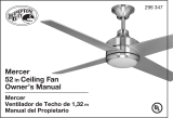
Installing the Light Kit
and Shatterproof Cover
Note: Before continuing installation, confirm that
the power is still turned off at the main circuit
breaker or by removing the the circuit fuse.
Turning the power off using a wall switch is not
sufficient to prevent electrical stock.
Step 1. Hold the light kit close to the switch
housing and securely attach the 2-pin connectors.
Step 2. Tuck the connections neatly into the light
kit. Align three round holes on the light kit and
switch housing. Securely tighten with 3 screws
(Fig.15)
Step 3.
Secure the Shatterproof Cover to the switch
housing by twisting in a clockwise direction. Do
not over-tighten(Fig.16).
Figure 15
Figure 16
Switch
housing
Shatterproof
Cover

9. Operating Your Transmitter
Restore power to ceiling fan and test for proper
operation.
1. “0 , 1 , 2 , 3 , 4 , 5 , 6” buttons:
These seven buttons are used to set the fan speed
as follows:
0 = Turn the fan ON/OFF
1 = Minimum speed
2 = Low speed
3 = Medium low speed
4 = Medium speed
5 = Medium high speed
6 = High speed
2. The “ ” button turns the light ON or OFF
and also controls the brightness seeting. Press
and release the button to turn the light ON or OFF.
Press and hold the button to set the desired
brightness.
3. “ ” button: Reverse switch (control the
direction)
Figure 17
Attach the remote control holder with the remote
control holder mounting screw. (Figure 18)
Install a 3V battery (included) into the remote
control. To prevent damage to the remote control,
remove the battery if not use for long periods.
(Figure 18)
Installing the Remote Control
Holder and Battery
Figure 18
Qx 2

Speed settings for warm or cool weather depend
on factors such as the room size, ceiling height,
number of fans, etc.
Warm weather - (Counter-Clockwise direction)
A downward air flow creates a cooling effect.(Fig.
19) This allows you to set your air conditioner on
a higher setting without affecting your comfort.
Cool weather - (Clockwise direction) An upward
airflow moves warm air off the ceiling area. (Fig.
20) This allows you to set your heating unit on a
lower setting without affecting your comfort.
Figure 19
Figure 20
Care of Your Fan
10.
Here are some suggestions to help you maintain
your fan
1. Because of the fan's natural movement, some
connections may become loose.
Check the
support connections, brackets, and blade
attachments twice a year.
Make sure they are
secure.
(It is not necessary to remove fan from
ceiling.)
2. Clean your fan periodically to help maintain its
new appearance over the years. Use only a soft
brush or lint-free cloth to avoid scratching the
finish. The plating is sealed with a lacquer to
minimize discoloration or tarnishing. Do not use
water when cleaning. This could damage the
motor, or the wood, or possibly cause an electrical
shock.
3.
There is no need to oil your fan.
The motor
has permanently lubricated bearings.
IMPORTANT
MAKE SURE THE POWER IS OFF AT
THE ELECTRICAL PANEL BOX BEFORE
YOU ATTEMPT ANY REPAIRS. REFER
TO THE SECTION "MAKING
ELECTRICAL CONNECTIONS".

11.
Troubleshooting
Solution
1. Check circuit fuses or breakers.
2. Check line wire connections to the fan and switch wire connections in the switch housing.
CAUTION: Make sure main power is off.
1. Make sure all motor housing screws are snug.
2. Make sure the screws that attach the fan blade bracket to the motor hub is tight.
3. Make sure wire nut connections are not rubbing against each other or the interior wall of the switch housing.
CAUTION: Make sure main power is off.
4. Allow a 24-hour "breaking-in" period. Most noise associated with a new fan disappear during this time.
5. If using an optional light kit, make sure the screws securing the lampshade are tight.
6. Make sure the upper canopy is a short distance from the ceiling. It should not touch the ceiling.
1. Do not connect the fan with wall mounted variable speed control (s).
Problem
Fan will not start.
Fan sounds noisy.
Remote control
malfunction

Specifications
12.
12.34
lbs
15.21
lbs
2.34'
Fan Size Speed Volts Amps Watts RPM CFM N.W. G.W. C.F.
52"
Low
High
120
120
These are approximate measures. They do not include Amps and Wattage used by the light kit.
0.05
0.29
2.05
18.77
51
173
1631.89
5983.50
Questions?
Call our Customer Care Team at 1-855-303-4229
www.urbanambiance.com
/