Page is loading ...

Texmate, Inc. Tel. (760) 598-9899 • www.texmate.comPM-35U Manual (P1) Page 1
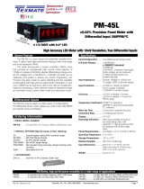
A Low Cost Easy To Use General Purpose Meter
PM-35U
Standard Range 2V
3 Optional DC Input Ranges
from 200mV to 200V
General Features Specifications
Input Configuration: ......True differential and single-ended
Full Scale Ranges: ........±199.9mVDC
±1.999VDC (standard)
±19.99VDC
±199.9VDC
Input Impedance: ...........Exceeds 1000MΩ on 200mV and
2V ranges; 10MΩ on all other
ranges
Input Protection: ............±250VDC or 175VAC maximum on
200mV and 2V ranges; ±1200VDC
or 850VAC on all other ranges
Accuracy: .......................±(0.1% of reading + 1 digit)
Temperature Coefficient: ..5PPM/°C in ratiometric operation; 80
to 100PPM/°C using internal
reference on 200mV and 2V ranges
Warm Up Time: ..............2 minutes to specified accuracy
Conversion Rate: ...........3 readings per second nominal
Display:...........................0.4" LED
Decimal Selection: ........User programmable to 3 positions
Overrange Indication: ...When input exceeds full scale on
any range being used, most
significant “1” digit & polarity symbol
are displayed with all other digits
blank
Power Requirements: ...+4.5 to +5.5VDC at 200mA max.
Operating Temperature: ....0° to +60°C
Storage Temperature: ...-20° to +70°C
Relative Humidity ..........95% (non-condensing)
Case Dimensions: .........Bezel 2.76” x 1.17” (69.75 x 29.7mm)
Depth behind Bezel 3.32”(84mm)
plus 0.68” (17.27mm) for connector.
Weight: .............................88 gms (3.1 oz)
PM-Series
View more application connections and connection
instructions on page 3.
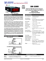
SINGLE-ENDED METER- 200mV Range, >2V Range 200mV Range:
1) Change R6 from 470k to 47k, ±5%; 2) Change R9 from 18.2k to
26.7k, ±1%; 3) Remove R8 (9.53k) and short with a jumper; 4) It is rec-
om mend ed that C4, C5 and C7 be changed to 0.22mF; 5) Adjust R10
until CV1=100mV.
>2V Range: Install R1 and R2 as specified under section titled Useful
Tables.
89
10
6
J
L
5VDC
-
+
F
R1
R2
7
H
E4
Cv1
D
R10
2k
R9
18.2k
R8
9.53k
C4
C6
R6
470k K
J1
-
+
+
Vin > 2V
Vin < 2V
-+
+5V
Typical Application Connections
The PM-35U Digital Panel Meter is an economical, high perfor-
mance instrument incorporating a number of fea tures usually
found only on more expensive meters. Utilizing the dual slope
method of integration, the unit measures differential and sin-
gle-ended DC voltages over five user selectable ranges from
199.9mV to 199.9V full scale.
Maximum res o lu tion is 100µV over ±1999 counts. Provision is
made for user con nec tions to provide various operating modes,
including a ra ti om et ric voltmeter, current meter, ratiometric ohm-
meter, and a tem pera ture difference meter.
The true differential input capability of the Model PM-35U is par-
ticularly useful for making accurate measurements of very small
signals in the presence of much larger common mode signals.
Because of its high noise immunity, it is also ideal for measuring
various balanced transducers and bridge inputs. When measur-
ing bridge circuits, long term drift of the excitation voltage can
be compensated for by using the ratiometric voltmeter mode of
operation.
PM-Series, high performance versatility for a wide range of applications
3 1/2 DIGIT with 0.4” LED
PM-35A .................... 3.5 digit Red LED, Precision Preference, 2VDC, 5VDC Power
PM-35U.................... 3.5 digit Red LED, Low Cost, 2VDC, 5VDC Power
PM-45L ................ 4.5 digit Red LED, Precision Meter w/Differential Input
PM-45X ............... 4.5 digit LCD, Precision Meter w/Differential Input
PM-45XU ................. 3.5 digit LCD, Low Cost Meter w/Differential Input

Texmate, Inc. Tel. (760) 598-9899 • www.texmate.comPage 2 PM-35U Manual (P1)
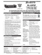
Functional Diagram
12
3
4
5
6
7
8
AB
D
E
F
H
J
KL
910
VOLTAGE
DIVIDER
SIGNAL
HIGH
INPUT
SIGNAL
HIGH
INPUT
SIGNAL
LOW
INPUT
ANALOG
COMMON
REFERENCE
VOLTAGE
OUTPUT
REFERENCE
INPUT
POWER
GROUND INPUT
+5VDC
SYSTEM
POWER INPUT
DECIMAL SELECTION
DISPLAY
TEST
+5V
BUFFER
J1
+5V
R9
18.2k
R10
2k
R8
9.53k
LOGIC
CIRCUITRY
R1
R2
R4
220k
C5
0.1 F
-3.5VDC C1
47 F
16V
C2
47 F
16V
23
+5V
R6, 470k C6, 0.22 F
INTEGRATOR COMPARATOR
C8
100pF
C4
.047 F
4
R7
100K
R13
680
C7
0.1 F
μ
Ω
μ
μ
μ
μ
μ
220k Ω
Ω
R3
∏
OPTIONAL COMPONENTS
ARE SHOWN DOTTED
+
-
Connector Pinouts
The Texmate Model PM-35U inter con nects by means of a stan-
dard PC board edge connector having two rows of 10 pins, spaced
on 0.156" centers. Connector are available from Texmate, or from
almost any connector manu fac turer. Pro vi sion has also been made
for direct solder termination to the PC board, thus elimi nat ing the
need for a connector. Please note that the warranty will be void if
there is any damage due to soldering.
1
A
2
B
3
C
45678910
DE FH JKL
Calibration Pot
Component Side Solder Side
10 L
9K
8J
7H
6F
5E
4D
3C
2B
1A
DECIMAL SELECT COMMON
DECIMAL SELECT (1X.XX)
DECIMAL SELECT (1.XXX)
REFERENCE VOLTAGE OUTPUT
DISPLAY TEST
SIGNAL HIGH INPUT
VOLTAGE DIVIDER SIGNAL HIGH INPUT
SIGNAL LOW INPUT
POWER GROUND INPUT
+5VDC SYSTEM POWER INPUT
DECIMAL SELECT (1XX.X)
DECIMAL DECIMAL SELECT COMMON
REFERENCE INPUT
ANALOG COMMON
SIGNAL HIGH INPUT
VOLTAGE DIVIDER SIGNAL HIGH INPUT
SIGNAL LOW INPUT
POWER GROUND INPUT
+5VDC SYSTEM POWER INPUT
Pins A, 1 and 3- Decimal Select: Decimal points may be dis-
played as required by connecting appropriate pin to Decimal
Select Common Pins B or 2.
Pins B and 2- Decimal Select Common: Decimal points are dis-
played as required by connecting Pins B or 2 to the appropriate
Decimal Select Pins A, 1, or 3.
Pin D- Reference Input: Reference voltage input for A to D con-
vert er. Normally supplied from Reference Voltage Output Pin 4
which is internally jumpered to Pin D by way of Junction J1. Pin D
may be used as an input for ratiometric measurements. Minimum
usable voltage is .05VDC with +4.0VDC being the maximum.
Pin E- Analog Common: 2.8V output referenced to +5V System
Power Input L, approximately +2.2V output referenced to Power
Ground Input Pin K.
Pins F and 6- Signal High Input: Signal high input of A to D con-
verter. Maximum overvoltage protection is 250VDC or 175VAC.
Pins H and 7- Voltage Divider Signal High Input: Signal high
input for voltages that require attenuation or scaling. Dividing resis-
tors R1 and R2 may be mounted internally for voltages up to 200V
max. Matched dividing resistors for 2V (1/10) and 200V (1/100)
ranges are available from Texmate. Shunt resistors for current
measurements up to 200mA may be internally mounted in the R2
position. The current loop is then applied to Signal High Input Pin
F and returned through Pin J or Pin 8.
Pins J and 8- Signal Low Input: Signal low input of A to D con-
vert er. Maximum overvoltage protection is 250VDC or 175VAC.
Pins K and 9- Power Ground Input: Negative terminal of + 5VDC
power should be connected to Pin 9. All digital signals, decimal
points, display test, and overrange should be returned to this
ground point.
Pins L and 10- +5VDC System Power Input: Meter requires
regulated (±10%) 5VDC power at approximately 200mA.
Pin 4- Reference Voltage Output: Internal precision voltage
ref er ence. Standard output is 1.000V, adjustable to ±5% by R10
potentiometer. Usable voltages from .05V to 2.8V for special high
impedance scaling can be obtained by changing the value of inter-
nal dividing resistors R8 and R9.
Pin 5- Display Test: All segments will light up when Pin 5 is con-
nected to +5VDC System Power Input Pin L or Pin 10.
Component Layout
R13 R10 R9 R8 R7 C8
C7
C5
C4
C6
C2C1R6R3R4
R2
R1
Signal Conditioning Components
SPAN Potentiometer (Pot)
The SPAN pot is on the right side of the dis-
play. Typical adjustment is 20% of the input
signal range.
Calibration Procedure
Apply power to the meter. Then with a precision DC reference source,
apply +1.900VDC be tween the Sig nal High Input Pin F and the Signal
Low Input Pin J. Adjust R10 po ten ti om e ter (on left side as viewed
from rear) until the display reads +1.9900V. Note: The voltage ap plied
in this case is for a ±1.999V F.S. meter. For other ranges, the voltage
applied should be similarly pro por tion ate to the particular full scale
voltage.
CAUTION: This meter employs high impedance CMOS inputs. Although internal
protection has been provided for several hundred volt overloads, the meter will
be destroyed if subjected to the high kilovolts of static discharge that can be
produced in low humidity environments. Always handle the meter with ground protection.
SOLDER SIDE
J1
COMPONENT SIDE

Texmate, Inc. Tel. (760) 598-9899 • www.texmate.comPM-35U Manual (P1) Page 3
described in the text.
NOTE: Use of these application circuits is entirely at the risk and
responsibility of the user and any user modification of the meter may at
the discretion of Texmate, void the warranty. (See rear page for user's
responsibility and warranty details) The following legend applies to
all application circuits: 1) optional component positions are shown in
dotted lines; 2) internal solder junctions are shown by for a closed
junction or for an open junction; 3) calibration voltages as mea-
sured by an external user supplied voltmeter are shown by
Typical Application Connections
The PM-35U may be used in a wide variety of configurations.
The following circuits illustrate some of the possibilities and
demonstrate the exceptional versatility of Texmate products.
Components called for in the applications which are not part
of the standard meter may be supplied by the user or in some
cases purchased from Texmate. The circuit diagrams explain
the basic pinout connections required for each application.
Unless otherwise specified, the diagrams will show the com-
ponent values and solder junctions that would normally be
installed on a standard 2V range meter. For those applications
which have alternative ranges and/or input configurations,
the required component values and any modifications are
F.S. In Rs External Resolution
20A 0.01 10mA
2A 0.1 1mA
F.S. In Rs Internal Resolution
200mA 1 100µA
20mA 10 10µA
2mA 100 1µA
200µA 1k 100nA
F.S. In Rs+RT Resolution
200 100 100m
2k 1k 1
20k 10k 10
200k 100k 100
2M 1M 1k
20M 10M 10k
F.S. In R1 R2 Resolution
200mV omit omit 100µV
2V omit omit 1mV
20V 9M 1M 10mV
200V 10M 100k 100mV
VOLTAGE RANGE CHANGE CURRENT RANGE CHANGE (*)
Use 200mV F.S. meter for minimum voltage drop.
OHMMETER RANGE CHANGE
Useful Tables
DIFFERENTIAL METER - 200mV RANGE, >2V Range, or
EXTERNAL REFERENCE
200mV Range : 1) Change R6 from 470k to 47k, ±5%; 2) Change
R9 from 18.2k to 26.7k, ±1%; 3) Remove R8 (9.53k) and short with
a jumper; 4) It is rec om mended that C4, C5 and C7 be changed to
0.22mF; 5) Adjust R10 until CV1= 100mV.
>2V Range: Install R1 and R2 as specified under section titled
Useful Tables.
External Reference: 1) Cut open solder junction J1; 2) Con nect
Pin E to Pin K;3) Connect moving arm of RB to Pin D.
SIMULTANEOUS VOLTAGE AND CURRENT MEAS URE MENT
1) Connect meter as for 200mV voltmeter for minimum drop on
Rs or R2. Use Rs externally for currents greater than 200mA;
2) Install R1, R2, and Rs as specified under section titled Useful
Tables. NOTE: Rs must be located in low side of the current loop
and Signal Low Input Pin J of voltmeter must not be grounded. If it
is necessary to install Rs on the high side of the current loop, the
ammeter must be op er at ed from an isolated power supply.
RATIOMETRIC VOLTMETER
Reading =(V1 ÷ V2) x 1000 where -2V ≤ V1 ≤
+2.8V and +100mV ≤ V2 ≤ +4V and 0000 <
Reading <1999. Cut open solder junction J1.
DIFFERENTIAL RATIOMETRIC OHM ME TER
1) Select RL so that the voltage drop across RL
is not less than 3V for that range in F.S., or use
a 3.9V Zener diode instead of RL; 2) Install RS
and RT as specified under sec tion titled Useful
Tables; 3) Cut open solder junction J1.
SINGLE-ENDED CURRENT METER
1) Connect meter as for 200mV voltmeter;
2) Install Rs. NOTE: Rs must be externally
mounted when current is greater than 200mA.
Standard values for Rs are speci fied under
section titled Useful Tables. For all other
ranges, Rs may be internally mount ed in the
R2 po si tion.
89
10
6
JK
L
5VDC
-
+
F
+
-
CURRENT
SHUNT
RESISTOR Rs R2
Vo
R LOAD
L
89
10
6
J
L
5VDC
-
+
F
R1
R2
7
H
E4
Cv1
D
R10
2k
R9
18.2k
R8
9.53k
C4
C6
R6
470k K
J1
-+
+5V
+
-
Vo
CCRR
RRC
CV12V+V
.CV-1.5Vo+2.8V
R
R
RRC
V2V
V2V
R
R
R
C
V
V
V
89
10
6
JK
L
5VDC
-
+
F
4E
CUT J1
OPEN
D
3.9 V ZENER
R (CURRENT LIMITING)
L
DEVICE
UNDER
TEST Rx
Rs
STANDARD
RT
89
10
6
JK
L
5VDC
-
+
F
V1
4E
V2
+
-
+
-
CUT J1
OPEN
D
89
10
6
JK
L
F
CURRENT
SHUNT
RESISTOR Rs R2
Vo
8
9
10
6
J
K
L
5VDC
-
+
F
R1
R2
R
LOAD
L
AMMETER
7
+
-
VOLT
DO NOT GROUND THIS WIRE
VOLTMETER
H
MEASURE TEMPERATURE DIFFERENCE
Meter Reading =199.9˚C Max. where
-50˚C≤(T1, T2)<+150˚C.
5VDC POWER SUPPLY MONITOR
Install R1 and R2 with component
values shown.
7VDC TO 20VDC POWER SUPPLY MONITOR
Install R1 and R2 with values shown.
8
F
9
10
6
JK
L
820 �820 �
T1
LM135
T2
LM135
5VDC
-
+
8
9
10
6
J
K
L
-
+
F
R1
R2
7
H
9M
1M
Ω
Ω
LM341P5V
7 ~ 20VDC
0.1 F
μ
8
9
10
6
J
K
L
5VDC
-
+
F
R1
R2
7
H
9M
1M
�
�
"NOTE: PM-35U meters are intended for use by skilled end users
and support "DIY" features that may permanently modify the
product involved. Texmate CAN NOT provide detailed technical
support or use notes beyond what is covered in our documen-
tation and warranty coverage will only apply to meters in an un-
modied condition. Repair, maintenance, and calibration through
Texmate are available as a paid service through our website or by
sending an RMA request to "[email protected]"."

Texmate, Inc. Tel. (760) 598-9899 • www.texmate.comPage 4 PM-35U Manual (P1)
Ordering Information
Standard Options for this Model Number
Part Number Description
4BASIC MODEL NUMBER
PM-35U .....3.5 digit Red LED, Low Cost, 2VDC, 5VDC pwr
Note: For operation, the PM-35U requires a CN-L10 Dual Row 10
Pin PCB edge connector 0.156” center or equivalent (see acces-
sories).
Special Options and Accessories
Part Number Description
4SPECIAL OPTIONS
(Specify Inputs & Req. Reading
)
ZS..........Custom display scaling within standard ranges
ZR-200V ....200 VDC Range Change.
ZR-20V ......20 VDC Range Change.
ZRS-200MV ..200 mVDC range change.
ZRS-PMRP...Non-standard range and scale.
4ACCESSORIES
CN-L10 ......Dual Row 10 Pin Connector, Solder Type
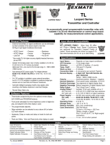
PM Case Dimensions and Panel Cutouts
Case Dimensions
TOP VIEW
FRONT VIEW
PANEL CUTOUT SIDE VIEW
16.82mm
0.662in
29.60mm
1.165in
14.50mm
0.571in
64.77mm
2.550 in
24.64mm
0.970in
69.90mm
2.752in
option metal
screw mounting clip
102.36mm
4.030in
84.50mm
3.330in
Edge connector
When extra panel mounting
tightness is required, optional
Screw Mounting Clips can be
purchased seperately and attach
to the sliding mounting side clips
8.50mm
0.335in
2.50mm
0.098in
Copyright © 2022 Texmate Inc. All Right Reserved.
WARRANTY
Texmate warrants that its products are free from defects in material and workmanship under
normal use and service for a period of one year from date of shipment. Texmate’s obligations
under this warranty are limited to replacement or repair, at its option, at its factory, of any of
the products which shall, within the applicable period after shipment, be returned to Texmate’s
facility, transportation charges pre-paid, and which are, after examination, disclosed to the sat-
isfaction of Texmate to be thus defective. The warranty shall not apply to any equipment which
shall have been repaired or altered, except by Texmate, or which shall have been subjected
to misuse, negligence, or accident. In no case shall Texmate’s liability exceed the original pur-
chase price. The aforementioned provisions do not extend the original warranty period of any
product which has been either repaired or replaced by Texmate.
USER’S RESPONSIBILITY
We are pleased to offer suggestions on the use of our various products either by way of printed
matter or through direct contact with our sales/application engineering staff. However, since
we have no control over the use of our products once they are shipped, NO WARRANTY
WHETHER OF MERCHANTABILITY, FITNESS FOR PURPOSE, OR OTHERWISE is made
beyond the repair, replacement, or refund of purchase price at the sole discretion of Texmate.
Users shall determine the suitability of the product for the intended application before using,
and the users assume all risk and liability whatsoever in connection therewith, regardless
of any of our suggestions or statements as to application or construction. In no event shall
Texmate’s liability, in law or otherwise, be in excess of the purchase price of the product.
Texmate cannot assume responsibility for any circuitry described. No circuit patent or software
licenses are implied. Texmate reserves the right to change circuitry, operating software, speci-
fications, and prices without notice at any time.
PM-35U Technical Manual Copyright © 2022 Texmate Inc. All rights
reserved. Published by: Texmate Inc. USA. Information in this Technical
Manual is subject to change without notice due to correction or enhance-
ment. The information described in this manual is proprietary to Texmate,
Inc. and may not be copied, reproduced or transmitted, in whole or in part,
in connection with the design, manufacture, or sale of apparatus, device or
private label product without the express written consent of Texmate, Inc.
1934 Kellogg Ave., Carlsbad, CA 92008
Tel: 1-760-598-9899 • USA 1-800-839-6283 • 1-800-TEXMATE
Email: [email protected] • Web: www.texmate.com
/