STIEBEL ELTRON WPKI-W E Operating instructions

Category
Flat panel accessories
Type
Operating instructions
Operating and installatiOn instructiOns
Buffer cylinder with booster heater ange/heat pump compact installation set
» SBP 100 Komfort
» sBp-HF
» WpKi-H e
» WpKi-p e
» WpKi-W e
» WpKi-V
0
bar
2
4
1
3
65°C
20
0
40
60
80
100
120
°C
20
0
40
60
80
100
120
°C
20
0
40
60
80
100
120
°C
2
Dimensions in mm
Inhalt
1 Operating instructions 3
2 Installation instructions SBP 100 Komfort 3
3
Installation instructions SBF-HF 5
4
Installation instructions WPKI-H E,
WPKI-P E, WPKI-W E 6
5 Installation instructions WPKI-H E
and WPKI-V 10
6 Specification 12
Warranty 13
Environment and recycling 13
26_03_01_0345
280
880
510
562
510
350
45 °
10
26_03_01_0340
min. 2200
8
1
9
5
4
510
2
7
562
510
350
6
3
955
880
280
ca.100
282
756
45 °
52
10
26_03_01_0337
Dimensions in mm
3
2 Installation instructions SBP 100 Komfort for heating contractors
Safety
Intended use
The sealed wall mounted cylinder with 100
l capacity acts as buffer cylinder for heat
pumps.
Observe the application limits listed in the
chapter „Specification / Data table“.
The appliance is intended for domestic use, i.e.
it can be used safely by untrained persons. The
appliance can also be used in a non-domestic
environment, e.g. in a small business, as long
as it is used in the same way.
Any other use beyond that described shall
be deemed inappropriate. Observation of
these instructions and of instructions for any
accessories used is also part of the correct use
of this appliance.
Subject to the relevant system, observe the
installation instructions of the components of
which the system comprises.
WARNING Injury
The appliance may be used by
children aged 8 and up and persons with
reduced physical, sensory or mental
capabilities or a lack of experience provided
that they are supervised or they have been
instructed on how to use the appliance safely
and have understood the resulting risks.
Children must never play with the appliance.
Children must never clean the appliance or
perform user maintenance unless they are
supervised.
Equipment description
A buffer cylinder is recommended to ensure
trouble-free heat pump operation. In addition,
they are designed to separate both heat pump
and heating circuit volume flows.
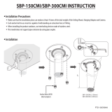
Equipment layout
There are four G 1 ¼” equipment connections
at the back of the cylinder, which are
matched to the WPKI- .... heat pump compact
installation set.
A G 1/2” connection is provided at the top of
the equipment for the air vent valve supplied
with the cylinder.
At the bottom of the equipment, an aperture is
provided for the electric booster heater.
1 Air vent valve
2 G 1 ¼” flow connector heat pump
compact installation set
3 G 1 ¼” return connector heat
pump compact installation set
4 G 1 ¼” heating flow connector
5 G 1 ¼” heating return connector
6 Type plate SBP 100
7 Cleaning aperture
8 Fill & drain valve
9 Panel
10 Connector with sensor well for return
temperature sensor
Special accessories
Heat pump compact installation sets
The heat pump compact installation sets
WPKI-P, WPKI-H, WPKI-W and WPKI-V are
components of the heat pump system and are
specifically designed for the SBP 100 buffer
cylinder.
Keep these instructions safely and
pass them on to any new user, should
the equipment change hands. Let your
contractor check their content in conjunction
with any maintenance or repair work.
1 Operating instructions for users and contractors
Safety
Only a qualified contractor should carry out
installation, commissioning, maintenance and
repair of the appliance.
General safety instructions
We guarantee trouble-free function and
operational reliability only if the original
accessories and spare parts intended for the
appliance are used.
Instructions, standards and regulations
Observe all applicable national and
regional regulations and instructions.
Transport and packaging
This wall mounted cylinder can be transported
vertically or horizontally.
To prevent cylinder damage, remove
the packaging only at the place of
installation.
Place of installation
The installation location should be protected
from frost. If the system is not in use at times
when a frost is likely, drain the cylinder and all
connected systems to prevent damage.
The room must be at least 2.2 m high.
Ensure that the wall at the installation location
is capable of bearing the full weight of the
cylinder. Install the cylinder vertically, as
shown in and .
Cylinder installation
Prior to fitting the cylinder to the wall, insert
the connector with the sensor well for the
return temperature sensor into the cylinder
body
-10 and -10.
It is recommended that the components in the
WPKl set and the respective circulation pump
are fitted to the cylinder and hand tightened
before the installation.
Fit the heat pump compact installation set
with circulation pumps (see page 6 section
3 “Installation instructions for accessories
WPKI-P, WPKI-H, WPKI-W” and page 11
section 4 “Installation instructions for
accessory WPKI-V”.
Fit the wall mounting panel or mounting
brackets to the respective wall and hook the
cylinder into one or the other fitting.
Observe the gap between the heat
pump and the cylinder .
Select fixing materials in accordance with the
wall construction/condition.
Fit the air vent valve into the top of
the cylinder
-1.
Maintenance
Regularly vent the safety valve until water
streams from it. Close the safety valve after
checking.
Commissioning
(only by a qualified contractor)
1. Fill and vent the cylinder.
2. Check the safety valve function.
Water connection
For connector allocation, see equipment
layout.
Implement the water connections in
accordance with the installation drawings in
the heat pump installation instructions.
For filling, venting and draining the
system, open the non-return valves
of the heat pump compact installation
set, i.e. set them to
. Then return them
into position
. The setting screw of the
WPKI-H non-return valve is located behind
the thermometer.
4
21
8
4
9
7
6 5
2
11
600
710
78.5 110
High limit safety cut-out Controller
1
13
C26_03_01_0336
13
8
10
12
C26_03_01_0339
26_03_01_0342
C26_03_01_0341
D0000035884
20
0
40
60
80
100
120
°C
5
Installing the electric booster heater
SBP-HF Part no. 074252
Instructions and regulations
DIN VDE 100
DIN VDE 0701
Regulations of your local electricity supply
company
The equipment type plate
The wall mounted cylinder with electric
booster heater is only designed for a
permanently connected power supply in
conjunction with the knock-out cable entry.
The equipment must be able to be separated
from the mains supply, for example by fuses,
which disconnect all poles with at least 3 mm
contact separation.
Fitting the booster heater flange:
Open the control chamber lid (
).
When retrofitting the heater:
Drain the water from the cylinder,
release the pipe fittings and remove the
equipment from the wall.
Remove the drain valve (to be re-used).
Remove the flange plate. The semi-shells,
pressure plate and insulating plate will
be re-used.
Install the booster heater flange into the
cylinder ( ), use new gaskets, push on
the insulating plate, position the pressure
plate inside the recess ( -12) of the
plastic casing, and tighten 10 screws
( -4) with 8 Nm.
Fit the drain valve ( -2) with a new
flange gasket and tighten with 20 Nm.
Fit the wiring set:
Fit the component support with 3 screws
( -1).
Fit the terminals ( -5 and 6).
Secure the earth strap with a self-tapping
screw (M5) (
-9) on the cylinder tab
( -10).
Secure the straps in the strap holders
( -8).
Insert the controller bulbs into the sensor
pipe ( -11) until the limiter clicks into
place ( ).
Push the red plug onto the booster heater
flange.
Mount the cylinder on the wall.
Install the heat pump compact installation
set WPKI-...
Fill the cylinder or the complete system with
water.
Power supply preparation
250 mm
26_03_01_0338
Route the power supply cable through the
PG21 fitting of the strain relief ( -7) and
connect in accordance with the connection
diagram (see wiring diagram ) at the
terminal strip ( -5).
Remove the knock-out in the strain relief
( -7) for the control cable from the heat
pump manager, and route the control
cable via the PG11 fitting into the cylinder.
Connect the control cable at the terminal
strip ( -6) at terminals 8-9.
Control chamber cover
Remove the adhesive cover strip.
Affix a new adhesive cover strip and push
firmly down.
Affix the wiring diagram pad to the
interior of the control chamber cover.
Undo the controller screws ( -2) from
the support and remove the temperature
selector (to be re-used later).
Position the control chamber cover and
secure with 4 screws.
Secure the controller to the control
chamber cover with the previously
undone screws.
Push the temperature selector ( -3)
onto the controller axis.
26_03_01_0343
65°C
Affix the rating plate of the booster heater
flange set on the l.h. side of the casing
( -13) and tick the selected output.
Install the safety valve into the
heating flow.
The safety valve must not be able to be
closed towards the cylinder.
The blow-off aperture of the safety valve
must remain open towards the atmosphere.
When using the heat pump compact
installation set WPKI-H, the safety valve can
be inserted into the threaded hole provided
for this purpose in the upper pipe bend (
).
Before and after fitting the control
chamber cover, the contractor must
carry out the following checks in accordance
with DIN VDE 0701
[or local regulations] after fitting the electric
booster heater:
Visual inspection of:
The condition and security of the control
chamber cover, the adhesive strip and
the temperature selector.
Connecting cables.
Strain relief and cable routing.
Cable routing.
Positioning of the capillary tubes from
the temperature controller and the
temperature limiter.
Check the earth connection
Check the ionisation resistance
Check the system for leaks
Check the safety valve function
Check the safety labels
Function check
Check the heating up and the first
switching of the temperature controller.
26_03_01_0344
3 Installation instructions SBF-HF for heating contractors
6
4 Installation instructions WPKI-H E, WPKI-P E, WPKI-W E in conjunction with the WPF....M, heat pumps
for heating contractors
4.1 General information
WPKI-H E Part no. 233098
Weight: approx. 3.5 kg
WPKI-P E Part no. 233097
Weight: approx. 5.1 kg
WPKI-W E Part no. 233099
Weight: approx. 3.8 kg
The heat pump compact installation sets
WPKI-P E , WPKI-H E, WPKI-W E and WPKI-V
are components of the heat pump system and
are specifically designed for the SBP 100 buffer
cylinder in conjunction with the WPF...M heat
pumps.
These heat pump compact installation sets
offer contractors a clear and easy to manage
connection of the SBP buffer cylinder to the
heat pump, the heating system and the DHW
cylinder.
Required special accessories
Circulation pumps Part no.
UP 25 7.0 E 232942
UP 25 7.5 E 232943
UP 25/1-7 E 231187
4.2 Assembly
These sets are supplied as prepared
assemblies.
All pre-assembled parts are factory sealed.
It is recommended that the set components
and the respective circulation pump (see
accessories) are fitted to the cylinder and hand
tightened before the installation.
Tighten the fittings once all components have
been connected to the cylinder, have been
aligned and secured with the wall retainers.
An Allen key (SW 5) is required to open and
close the ball shut-off valves in the heat pump
return.
Circulation pumps
Observe the flow direction when fit-
ting the circulation pump.
HE circulation pumps should never
be switched directly. Use an external
relay with a breaking capacity of at least
10A/250VAC or our relay set WPM-RBS.
For the circulation pump rating curve, see
page 13.
4.2.1 WPKI-H E
The WPKI-H E set comprises all necessary
components for connecting the heating system
to the SBP 100 buffer cylinder.
Heating flow
1 Connection bend G 1 ¼” with safety valve
connector
2 Wall retainer
3 Ball shut-off valve G 1”
4 Handle with inserted thermometer
5 Connector G 1” with ball shut-off valve
Heating return
6 Connector G 1 ¼”
7 Connector G 1” with ball shut-off valve
8 EPS insulation pieces
Assembly according to Fig.
and .
Shorten the threaded wall retainer rod subject
to the distance to the wall, at which the
cylinder was mounted
.
It must not be possible to shut-off the safety
valve against the heat source.
Fit the heating flow (
-a) and the heating
return ( -b).
4.2.2 WPKI-P E
The WPKI-P E set comprises all necessary
components for connecting the heat pump to
the SBP 100 buffer cylinder:
Heat pump flow
1 Connection bend G 1 ¼”
2 Wall retainer
3 Ball shut-off valve with non-return valve
4 Handle with inserted thermometer
5 Ball shut-off valve
6 Connector G 1 ¼”
7 Safety valve with pressure gauge
Heat pump return
8 Connector G 1 ¼” with sensor well for
return temperature sensor
9 Ball shut-off valve
10 Connector G 1 ¼” with connection for fill &
drain valve and expansion vessel
11 EPS insulation pieces
Assembly according to Fig.
, and .
Shorten the threaded wall retainer rod subject
to the distance to the wall, at which the
cylinder was mounted
.
It must not be possible to shut-off the safety
valve against the heat source.
Connect the expansion vessel and the fill &
drain valve at the connector provided (
-e).
Fit the heat pump flow ( -d) and the heat
pump return ( -c).
4.2.3 WPKI-W E
The WPKI-W E set
comprises all necessary
components for connecting a DHW cylinder.
DHW flow
1 Connector G 1” with ball shut-off valve and
non-return valve
2 Handle with inserted thermometer
3 Ball shut-off valve
4 Connection bend
5 Connector G 1 ¼” for installing the heat
pump flow
DHW return
6 Connection G 1 ¼” for installing the heat
pump return.
7 EPS insulation pieces
Assembly according to Fig.
and .
Install the tee with shut-off valve (
-1) into
the heat pump return.
Fit the heat pump flow (
-d), the heat pump
return ( -c) and the cylinder return ( -f).
Connect the expansion vessel and the fill &
drain valve at the connector provided (
-e).
7
Wall retainer
20
0
40
60
80
100
120
°C
0
bar
2
4
1
3
20
0
40
60
80
100
120
°C
C26_03_01_0330
D0000035880
1
2
3
6
8
7
5
4
1
2
3
6
8
7
4
5
9
10
11
1
2
3
6
7
5
4
WPKI-P EWPKI-H E
WPKI-W E
20
0
40
60
80
100
120
°C
830 mm
D0000035879
D0000035881
DEUTSCH
8
Wall retainer
1. 2.1.2.
a b c e d
1.
2.
c
e d
f1
WPKI-P EWPKI-H E
WPKI-W E
20
0
40
60
80
100
120
°C
20
0
40
60
80
100
120
°C
20
0
40
60
80
100
120
°C
20
0
40
60
80
100
120
°C
20
0
40
60
80
100
120
°C
D0000035883
D0000035882
9
Connection diagram
SBP 100 mit WPF....M
D0000035885
10
5.1 General information
WPKI-H E Part no. 233098
Weight: approx. 3.5 kg
WPKI-V Part no. 074347
Weight: approx. 3.0 kg
The heat pump compact installation sets
WPKI-H and WPKI-V are components of
the heat pump system and are specifically
designed for the SBP 100 buffer cylinder in
conjunction with the WPF heat pump.
These heat pump compact installation sets
offer contractors a clear and easy to manage
connection of the SBP buffer cylinder to the
heat pump and the heating system.
Required special accessories
Circulation pumps Part no.
UP 25 7.0 E 232942
UP 25 7.5 E 232943
UP 25/1-7 E 231187
5.2 Assembly
These set are supplied as prepared
assemblies.
All pre-assembled parts are factory sealed.
It is recommended that the set components
and, in case of the WPKl-H E, the respective
circulation pump are fitted to the cylinder and
hand tightened before the installation.
Tighten the fittings once all components have
been connected to the cylinder, have been
aligned and secured with the wall retainer
(only WPKI-H E).
5.2.1 WPKI-H E
The WPKI-H E set
comprises all necessary
components for connecting the heating system
to the SBP 100 buffer cylinder.
Heating flow
1 Connection bend G 1 ¼” with safety valve
connector
2 Wall retainer
3 Ball shut-off valve G 1”
4 Handle with inserted thermometer
5 Connector G 1” with ball shut-off valve
Heating return
6 Connector G 1 ¼”
7 Connector G 1” with ball shut-off valve
8 EPS insulation pieces
Assembly according to Fig.
and .
Shorten the threaded wall retainer rod subject
to the distance to the wall, at which the cylin-
der was mounted .
Fit the heating flow (
-a) and the heating
return ( -b).
An Allen key (SW 5) is required to open and
close the ball shut-off valve in the heating
return.
Circulation pumps
Observe the flow direction when fit-
ting the circulation pump.
HE circulation pumps should never
be switched directly. Use an external
relay with a breaking capacity of at least
10A/250VAC or our relay set WPM-RBS.
For the circulation pump rating curve, see
page 13.
5.2.2 WPKI-V
The WPKI-V set
comprises all necessary
components for connecting the WPF heat
pump to the SBP 100 buffer cylinder and the
DHW cylinder.
Heat pump flow
1 Connector G 1 ¼” with ball shut-off valve
2 Non-return valve
3 Connector G 1 ¼”
Heat pump return
4 Connector G 1 ¼” with sensor well for re-
turn temperature sensor
5 Ball shut-off valve
6 Connector G 1 ¼” with connection for fill &
drain valve and expansion vessel
Assembly according to Fig.
and .
Connect the expansion vessel and the fill &
drain valve at the connector provided (
-c).
Fit the heat pump flow ( -e), the heat pump
return ( -d) and the cylinder return
( -f).
An Allen key (SW 5) is required to open and
close the ball shut-off valve in the heating
return.
5 Installation instructions WPKI-H E, WPKI-V in conjunction with the WPF heat pump for the installer
11
Wall retainer
1
3
4
5
6
WPKI-V
2
c
d
e
WPKI-V
WPKI-H E
1.
2.
a
b
f
415 mm
C26_03_01_0333
20
0
40
60
80
100
120
°C
1
2
3
6
8
7
5
4
WPKI-H E
20
0
40
60
80
100
120
°C
D0000035879
D0000035888
C26_03_01_0335
12
Connection diagram
SBP 100 with WPF 5....13
6. Specification
Data table
SBP 100 Komfort
185443
Application limits
Max. permissible pressure MPa 0.3
Test pressure MPa 0.45
Max. permissible temperature °C 95
Hydraulic data
Rated capacity l 100
Energy data
Standby energy consumption/24 h at 65 °C kWh 0.9
Dimensions
Height mm 955
Width mm 510
Depth mm 510
Weights
Weight (wet) kg 142.5
Weight (dry) kg 42.5
Connections
Heat pump connection G 1 1/4 A
Heating connection G 1 1/4 A
Air vent valve connection G 1/2
D0000035887
13
Warranty
The warranty conditions of our German companies do not
apply to appliances acquired outside of Germany. In countries
where our subsidiaries sell our products, it is increasingly the
case that warranties can only be issued by those subsidiaries.
Such warranties are only granted if the subsidiary has issued
its own terms of warranty. No other warranty will be granted.
We shall not provide any warranty for appliances acquired in
countries where we have no subsidiary to sell our products.
This will not aect warranties issued by any importers.
Environment and recycling
We would ask you to help protect the environment. After use,
dispose of the various materials in accordance with national
regulations.
Circulation pump rating curves
Δp-c
max.
max.
232942
UP 25 7.0 E
0 0,5 1,0 1,5 2,0 2,5 3,0
0 0,5 1,0 1,5 2,0 2,5 3,0
0
1
2
3
4
5
6
7
0
20
40
D0000033563
X = Delivery flow rate in m
3
/h
Y = Pump head in m
Z = Power consumption in W
Δp-c
max.
max.
0 0,5 1,0 1,5 2,0 2,5 3,0 4,0 5,0
4,0 5,00 0,5 1,0 1,5 2,0 2,5 3,0
0
1
2
3
4
5
6
7
0
20
40
232943
UP 25 7.5 E
D0000034116
X = Delivery flow rate in m
3
/h
Y = Pump head in m
Z = Power consumption in W
0
25
75
50
0
1
2
3
4
5
7
8
6
1 2 3 4 5
1 2 3 4 5
231187
UP 25/1-7E
6 m
5 m
4 m
3 m
2 m
1 m
min
max
6 m
5 m
4 m
3 m
2 m
1 m
min
84_03_01_0124
X = Delivery flow rate in m
3
/h
Y = Pump head in m
Z = Power consumption in W
14
Notes
15
Notes
Deutschland
STIEBEL ELTRON GmbH & Co. KG
Dr.-Stiebel-Straße 33 | 37603 Holzminden
Tel. 05531 702-0 | Fax 05531 702-480
www.stiebel-eltron.de
Verkauf Tel. 05531 702-110 | Fax 05531 702-95108 | info-center@stiebel-eltron.de
Kundendienst Tel. 05531 702-111 | Fax 05531 702-95890 | [email protected]
Ersatzteilverkauf Tel. 05531 702-120 | Fax 05531 702-95335 | [email protected]
Irrtum und technische Änderungen vorbehalten! | Subject to errors and technical changes! | Sous réserve
d‘erreurs et de modifications techniques! | Onder voorbehoud van ver
g
issin
g
en en technische wi
j
zi
g
in
g
en! |
Salvo error o modificación técnica! | Excepto erro ou alteração técnica | Zastrzeżone zmian
y
techniczne i
ewentualne błęd
y
| Om
y
l
y
a technické změn
y
j
sou v
y
hrazen
y
! | A muszaki változtatások és tévedések
j
o
g
át
fenntartjuk! |
Отсутствие ошибок не гарантируется. Возможны технические изменения.
| Chyby a
technické zmeny sú vyhradené! Stand 8845
Australia
STIEBEL ELTRON Australia Pty. Ltd.
4/8 Rocklea Drive | Port Melbourne VIC 3207
Tel. 03 9645-1833 | Fax 03 9645-4366
www.stiebel.com.au
Austria
STIEBEL ELTRON Ges.m.b.H.
Eferdinger Str. 73 | 4600 Wels
Tel. 07242 47367-0 | Fax 07242 47367-42
www.stiebel-eltron.at
Belgium
STIEBEL ELTRON bvba/sprl
't Hofveld 6 - D1 | 1702 Groot-Bijgaarden
Tel. 02 42322-22 | Fax 02 42322-12
www.stiebel-eltron.be
Czech Republic
STIEBEL ELTRON spol. s r.o.
K Hájům 946 | 155 00 Praha 5 - Stodůlky
Tel. 251116-111 | Fax 235512-122
www.stiebel-eltron.cz
Denmark
Pettinaroli A/S
Mandal Allé 21 | 5500 Middelfart
Tel. 06341 666-6 | Fax 06341 666-0
www.stiebel-eltron.dk
Finland
STIEBEL ELTRON OY
Kapinakuja 1 | 04600 Mäntsälä
Tel. 020 720-9988
www.stiebel-eltron.fi
France
STIEBEL ELTRON SAS
7-9, rue des Selliers
B.P 85107 | 57073 Metz-Cédex 3
Tel. 0387 7438-88 | Fax 0387 7468-26
www.stiebel-eltron.fr
Hungary
STIEBEL ELTRON Kft.
Gyár u. 2 | 2040 Budaörs
Tel. 01 250-6055 | Fax 01 368-8097
www.stiebel-eltron.hu
Japan
NIHON STIEBEL Co. Ltd.
Kowa Kawasaki Nishiguchi Building 8F
66-2 Horikawa-Cho
Saiwai-Ku | 212-0013 Kawasaki
Tel. 044 540-3200 | Fax 044 540-3210
www.nihonstiebel.co.jp
Netherlands
STIEBEL ELTRON Nederland B.V.
Daviottenweg 36
5222 BH 's-Hertogenbosch
Tel. 073 623-0000 | Fax 073 623-1141
www.stiebel-eltron.nl
Poland
STIEBEL ELTRON Polska Sp. z o.o.
ul. Działkowa 2 | 02-234 Warszawa
Tel. 022 60920-30 | Fax 022 60920-29
www.stiebel-eltron.pl
Russia
STIEBEL ELTRON LLC RUSSIA
Urzhumskaya street 4,
building 2 | 129343 Moscow
Tel. 0495 7753889 | Fax 0495 7753887
www.stiebel-eltron.ru
Slovakia
TATRAMAT - ohrievače vody, s.r.o.
Hlavná 1 | 058 01 Poprad
Tel. 052 7127-125 | Fax 052 7127-148
www.stiebel-eltron.sk
Switzerland
STIEBEL ELTRON AG
Industrie West
Gass 8 | 5242 Lupfig
Tel. 056 4640-500 | Fax 056 4640-501
www.stiebel-eltron.ch
Thailand
STIEBEL ELTRON Asia Ltd.
469 Moo 2 Tambol Klong-Jik
Amphur Bangpa-In | 13160 Ayutthaya
Tel. 035 220088 | Fax 035 221188
www.stiebeleltronasia.com
United Kingdom and Ireland
STIEBEL ELTRON UK Ltd.
Unit 12 Stadium Court
Stadium Road | CH62 3RP Bromborough
Tel. 0151 346-2300 | Fax 0151 334-2913
www.stiebel-eltron.co.uk
United States of America
STIEBEL ELTRON, Inc.
17 West Street | 01088 West Hatfield MA
Tel. 0413 247-3380 | Fax 0413 247-3369
www.stiebel-eltron-usa.com
A 272604-37339-8846
B 168843-37339-8846
4<AMHCMN=hcgaee>
  • Page 1 1
  • Page 2 2
  • Page 3 3
  • Page 4 4
  • Page 5 5
  • Page 6 6
  • Page 7 7
  • Page 8 8
  • Page 9 9
  • Page 10 10
  • Page 11 11
  • Page 12 12
  • Page 13 13
  • Page 14 14
  • Page 15 15
  • Page 16 16

STIEBEL ELTRON WPKI-W E Operating instructions

Category
Flat panel accessories
Type
Operating instructions

Ask a question and I''ll find the answer in the document

Finding information in a document is now easier with AI