Page is loading ...

268941
SBP 200 E, SPB 400 E, SBP 700 E, SBP 700 E SOL with WPKI 5
Operating and installation instructions
SBP 200 E / WPKI 5
1. Operating instructions 3
1.1 Cylinder description 3
1.2 Special accessories 3
1.3 Essential special accessories
1.4 Operating and installation instructions 3
2. Installation instructions 3
2.1 Cylinder construction 3
2.2 Regulations 3
2.3 Place of installation 3
2.4 Cylinder casing assembly/removal 3
2.5 Immersion heater installation 5
2.6 WPKl 3 installation 5
2.7 Commissioning 5
2.8 Maintenance 5
26_03_01_0222

2
7
6
5
SBP 200 E (SBP 400)
18 17
1
2
9
8
3
4
10
Dimensions in mm
1
2
10
8
14
10
11
11
7
6
5
4
Dimensions in mm
SBP 700 E / SBP 700 E SOL
10
9
13
12
16
15
15
A
B
C
D
C26_03_01_0225
26_03_01_0227
230
140
800
1535
140
295
Ø 630
(1710)
(925)
(250)
(320)
(Ø 750)
C26_03_01_0229
26_03_01_0225
C26_03_01_0225

3
2. Installation instructions for contractors
1. Instructions for users and contractors
SBP 200 E Part no: 18 54 58
SBP 700 E Part no: 18 54 59
SBP 400 E Part no: 22 08 24
SBP 700 E SOL Part no: 18 54 60
1.1 Cylinder description
The sealed freestanding cylinder (with a volu-
me of 200 or 700 litres) acts as buffer cylinder
for heat pumps.
A buffer cylinder is recommended to ensure
trouble-free heat pump operation. It acts as
a bridge during electricity supply shutdown
periods and as separator between the volume
flow in the heat pump and that in heating
circuits.
Features of the SBP 700 E SOL
The cylinder SBP 700 E SOL is also fitted with
a heat exchanger for boosting the DHW with
solar energy.
1.2 Special accessories
WPKI 5 Part no: 22 08 30
The compact installation heat pump set
WPKl 3 is designed especially for use with
buffer cylinders SBP 200 E, SBP 400 and
SBP 700 E (SOL). Clear and simple connection
of buffer cylinder SBP to heat pumps WPL.
WPKI 6 Part no: 22 08 31
The compact heat pump set WPKl 4 is desi
-
gned especially for use with buffer cylinders
SBP 200 E and SBP 700 E (SOL). Clear and sim
-
ple connection of buffer cylinder SBP to heat
pumps WPF.
Inserts Part no: 00 37 11
For close fitting pipe connection of the buffer
cylinder without heat pump compact installati
-
on WPKl 3. This set comprises 4 inserts,
4 gaskets and 4 union nuts G 2”.
Thermally insulated pressure hoses
G 1¼” x 1 m (DN 25) Part no: 07 44 15
G 1¼” x 2 m (DN 25) Part no: 07 44 16
G 1¼” x 5 m (DN 25) Part no: 07 44 17
G 1¼” x 1 m (DN 32) Part no: 07 44 14
G 1¼” x 2 m (DN 32) Part no: 18 20 19
G 1¼” x 5 m (DN 32) Part no: 18 20 20
1.3 Essential special
accessories
UP 25-60-180 Part no: 07 43 25
UP 25-80-180 Part no: 07 43 16
For further accessories, see the design docu
-
mentation.
1.4 Operating and installation in-
structions
Observe the operating and installation ins-
tructions of the components for each relevant
system.
Keep these operating instructions
in a safe place and pass them on to
any new user, should the equipment change
hands. Let your contractor check their con-
tent in conjunction before commencing any
maintenance or repair work
To prevent damage and contaminati-
on, we recommend that the cylinder
casing is removed for transportation and
installation (see 2.3).
Do not use a barrel clamp!
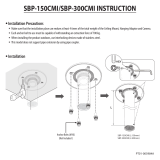
2.1 Cylinder construction
(A, B, E)
1 Ventilation connectors R ¾” and
combined
temperature and pressure relief valve
2 PUR foam thermal insulation
3 Steel container
4 G 2” flow connector, heat pump compact
installation
5 G 2” heating flow connector
6 G 2” heating return connector
7 G 2” return connector, heat pump compact
installation
8 G ½” connector with protective pipe for HP
return temperature sensor
9 Type plate (on the protective cover)
10 G 1½” connectors, for electric immersion
heater
11 G ½” connector, sealed with plug
12 G 1” flow connector, HE solar
(only SBP 700 E SOL)
13 G 1” return connector, HE solar
(only SBP 700 E SOL)
14 G ½” connector with protective sleeve for
temperature sensor (only SBP 700 E SOL)
15 G 1½” connector for additional heat source
16 PUR foam body, thermal insulation segment
17 Retaining strap
18 Buckle
19 Plastic casing
20 Plastic lid
21 Plastic plinth cover
2.2 Regulations
• Installation and commissioning, as well
as the maintenance of this equipment,
must only be carried out by an authori-
sed qualified contractor in accordance
with these instructions.
• Optimum function and safe operation
can only be assured when using original,
specialised accessories and spare parts
intended for this equipment.
2.3 Place of installation
The installation location should be safe from
frost. If the system is not in use at times when
frost is likely, drain the cylinder and the whole
system connected to it, to prevent damage.
Ensure that the floor at the installation loca
-
tion is a load bearing surface, which must be
level and even.
Secure the cylinder feet firmly to the floor to
prevent tipping.
Minimum ceiling height:
1.80 m for SBP 200 E,
2.00 m for SBP 400 E and
2.10 m for SBP 700 E.
2.4 Cylinder casing
assembly / removal
The cylinder casing is fitted in the delivered
condition. It can be removed if necessary.
Removal (E):
1. Removing the plastic lid (20)
2. Removing the plastic plinth cover (21)
3. Removing the plastic casing (19)
Installation in reverse order.
Fit the cylinder casing before instal-
lation work begins on the immersion
heater.
Features of the SBP 700 E and
the SPB 700 E SOL (B)
The two polyurethane foam segments, at-
tached to both sides of the cylinder, can be
removed to ensure safe transportation of the
cylinder through narrow passages and door-
SBP 200 E SBP 400 E SBP 700 E SBP 700 E SOL
Weight: empty:
full
kg
kg
56
256
82
482
145
845
176
876
Height of unit when tilted:
mm 1650 1800 2000 2000
Permissible operating pressure MPa (bar) 0,3 (3) 0,3 (3) 0,3 (3) 0,3 (3)

4
WPKI 5
E F
G
90
80
70
60
50
40
30
20
10
0
1 1,5 32,52 m³/h
hPa
SBP 200 E with WPKI 5
26_03_01_0220
C26_03_01_0222
26_03_01_0219
6
5
4
3
2
1
0
H (m)
Q (m³/h)
0 1 2 3 4
8
6
4
2
0
H (m)
Q (m³/h)
0 1 2 3 4 5 6 7 8
C26_03_01_0223
22
24
23
25
19
27
24
30
31
29
32
28
34
20
21
26
UP 25-80-180
UP 25-60-180
Open
Close
33

5
ways. To do this, undo the retaining straps (17)
at the buckles (18). In the installed condition,
the buckles should be near a joint (segment/
cylinder thermal insulation).
Information about using additional connectors
for the sensor protection sleeve of the SBP 700
cylinder (B)
Should it be necessary to install further sen-
sor protection sleeves in the cylinder, two
additional connectors are available at the top
and bottom, under the foam insulation (11).
To do this, drill holes at the marked places of
the plastic casing with, for example, a 70 mm
hole saw. Remove the thermal insulation from
around the connectors so that the sensor pro-
tection sleeves can be fitted.
2.5 Immersion heater installation
(C, D)
To boost the heat input, one electric immersi-
on heater can be installed into the
SBP 200 E and SBP 400 E (either from the right
or from the left); two immersion heaters can
be installed into model SBP 700 E. To do this,
remove the connector cap (10) and unscrew
the vent plug. Removing the vent plug requires
a socket wrench (SW 32).
2.6 WPKl 5 installation (E)
Set components
22 Connector
23 Temperature pressure gauge
24 Ball shut-off valve
25 Safety valve
26 G ¾” A connection for expansion vessel
27 Circulation pump (special accessory)
28 G 1¼” A HP flow connector
29 G 1¼” A HP return connector
30 G 1¼” I connector with ball shut-off valve
(heating flow)
31 G 1¼” I connector with ball shut-off valve
(heating return)
32 Fill/drain valve
33 Automatic air-vent valve (on-site provision)
34
Combined temperature and pressure re-
lief valve
Installation
The WPKI 5 set is delivered in pre-assembled
individual parts. All pre-assembled parts are
factory sealed.
It is recommended that the components in the
WPKl 5 set and the selected circulation pump
are connected to the cylinder and tightened by
hand before installation. Once all components
have been connected to the cylinder, tighten
all fittings. Connect the expansion vessel and
the fill/drain valve to the pre-determined con-
nector (32) and (26).
Connect heat pump flow and return to the
heat pump at positions (28) and (29).
Ensure that it is impossible to shut-
off the safety valve on the heat
source..
When there is a risk of frost in the alternative
system, install a drain valve on-site to drain
the external air/water heat pump (WPL con
-
nection hoses).
All shut-off devices are ball shut-off valves,
which provide a good seal. A spanner
(SW 19) is recommended to open and close
the shut-off valves (24).
Circulation pump (cylinder primary pump)
The pump output curve (F) and the pressure
loss of the WPKl 5 (
G) can provide helpful
information on which circulation pump set to
select. Subject to the heat pump type and the
following connection mode (
H), at standard
length, we recommend a circulation pump set
from the following table.
UP 32–60-180
UP 32–80-180
WPL 10
WPL 13
WPL 18
WPL 23
WPL 33
2.7 Commissioning
(to be implemented only by a quali-
fied contractor)
Fill and vent the freestanding cylinder.
Follow user and installation instruc-
tions and check the functions of spe-
cial accessories (immersion heater).
Check the safety valve function.
2.8 Maintenance
• When working on permanently fitted
electrical components, disconnect every
part of the equipment from the mains.
• Regularly vent the safety valve until
water flows from it. Shut off the safety
valve after the inspection.

6
C26_03_01_0851
H
18
3
6
9
19
13
14
2
1
500 mm max.
12
10
11
7
2
4
8
5
300 mm
min..
20
21
A
B
C
16
15
17
Valve outlet size Minimum size of
discharge pipe D1
Minimum size of discharge
pipe D2 from tundish
Maximum resistance allowed, expressed as a
length of straight pipe (i.e. no elbows or bends)
Resistance created by
each elbow or bend
G3/4 22 mm 28 mm
35 mm
42 mm
Up to 9 m
Up to 18 m
Up to 27 m
1.0 m
1.4 m
1.7 m
A Metal discharge pipe (D1) from temperature relief to tundish.
B Metal discharge pipe (D2) from tundish, with continuous fall. Ta
-
ble and worked example.
C Discharge below fixed grating.
1 Heat pump
2 Thermally insulated pressure hose
3 Heat pump controller
4 Outside temperature sensor
5 Buffer cylinder
6 Quick acting air-vent valve
7 Thermal pressure gauge
8 Safety valve
9 G 1¼” threaded connection,
(heat pump flow)
10 G 1¼” threaded connection,
(heat pump return)
11 Circulation pump (cylinder primary pump)
12 Temperature sensor HP return
13 Expansion vessel (on-site provision)
14 Fill & drain valve (on-site provision)
15 Circulation pump (heating circuit flow)
16 Overflow valve (for HP systems)
17 Temperature sensor - heating circuit flow
18 Temperature sensor HP flow
19 Air-vent valve
20 Combined temperature and pressure relief valve
21 Tundish

7
Guarantee
For guarantees please refer to the respective te
rms and conditions of supply for your country.
The installation, electrical connection
and first operation of this appliance
should be carried out by a qualified instal-
ler.
The company does not accept liability
for failure of any goods supplied
which have not been installed and operated
inaccordance with the manufacturer‘s ins-
tructions.
Environment and
recycling
Please help us to protect the environment by
disposing of the packaging in accordance with
the national regulations for waste processing.

Austria
STIEBEL ELTRON Ges.m.b.H.
Eferdinger Str. 73 | A-4600 Wels
Tel. 072 42-47367-0 | Fax 07242-47367-42
Email info@stiebel-eltron.at
www.stiebel-eltron.at
Belgium
STIEBEL ELTRON Sprl/Pvba
P/A Avenue du Port 104, 5 Etage
B-1000 Bruxelles
Tel. 02-4232222 | Fax 02-4232212
Email info@stiebel-eltron.be
www.stiebel-eltron.be
CCzech Republik
STIEBEL ELTRON spol. s r.o.
K Hájům 946 | CZ-15500 Praha 5-Stodůlky
Tel. 2-511 16111 | Fax 2-355 12122
Email info@stiebel-eltron.cz
www.stiebel-eltron.cz
Denmark
Exclusive Distributor.
PETTINAROLI A/S
Madal Allé 21 | DK-5500 Middelfart
Tel. 63 41 66 66 | Fax 63 41 66 60
Email info@pettinaroli.dk
www.pettinaroli.dk
France
STIEBEL ELTRON S.A.S.
7-9, rue des Selliers
B.P. 85107 | F-57073 Metz-Cédex 3
Tel. 03 87 74 38 88 | Fax 03 87 74 68 26
Email info@stiebel-eltron.fr
www.stiebel-eltron.fr
Great Britain
Exclusive Distributor.
Applied Energy Products Ltd.
Morley Way | GB-Peterborough PE2 9JJ
Tel. 087 09-00 04 20 | Fax 017 33-31 96 10
Email sales@applied-energy.com
www.applied-energy.com
Hungary
STIEBEL ELTRON Kft.
Pacsirtamezo´´ u. 41 | H-1036 Budapest
Tel. 012 50-6055 | Fax 013 68-8097
Email info@stiebel-eltron.hu
www.stiebel-eltron.hu
Netherlands
STIEBEL ELTRON Nederland B.V.
Daviottenweg 36 | Postbus 2020
NL-5202 CA‘s-Hertogenbosch
Tel. 073-6 23 00 00 | Fax 073-6 23 11 41
Email stiebel@stiebel-eltron.nl
www.stiebel-eltron.nl
Poland
STIEBEL ELTRON sp.z. o.o
ul. Instalatorów 9 | PL-02-237 Warszawa
Tel. 022-8 46 48 20 | Fax 022-8 46 67 03
Email stiebel@stiebel-eltron.com.pl
www.stiebel-eltron.com.pl
Russia
STIEBEL ELTRON RUSSIA
Urzhumskaya street, 4. | 129343 Moscow
Tel. (495) 775 3889 | Fax (495) 775-3887
Email info@stiebel-eltron.ru
www.stiebel-eltron.ru
Sweden
STIEBEL ELTRON AB
Friggagatan 5 | SE-641 37 Katrineholm
Tel. 0150-48 7900 | Fax 0150-48 7901
Email info@stiebel-eltron.se
www.stiebel-eltron.se
Switzerland
STIEBEL ELTRON AG
Netzibodenstr. 23 c | CH-4133 Pratteln
Tel. 061-8 16 93 33 | Fax 061-8 16 93 44
Email info@stiebel-eltron.ch
www.stiebel-eltron.ch
Thailand
STIEBEL ELTRON Asia Ltd.
469 Moo 2, Tambol Klong-Jik
Ampur Bangpa-In | Ayutthaya 13160
Tel. 035-22 00 88 | Fax 035-22 11 88
Email stiebel@loxinfo.co.th
www.stiebeleltronasia.com
United States of America
STIEBEL ELTRON Inc.
17 West Street | West Hateld MA 01088
Tel. 4 13-247-3380 | Fax 413-247-3369
Email info@stiebel-eltron-usa.com
www.stiebel-eltron-usa.com
Deutschland
STIEBEL ELTRON GmbH & Co. KG
Dr.-Stiebel-Straße | D-37603 Holzminden
Tel. 0 55 31 702 0 | Fax 0 55 31 702 480
Email info@stiebel-eltron.de
www.stiebel-eltron.de
Verkauf Tel. 0180 3 700705 | Fax 0180 3 702015 | info-center@stiebel-eltron.com
Kundendienst Tel. 0180 3 702020 | Fax 0180 3 702025 | kundendienst@stiebel-eltron.com
Ersatzteilverkauf Tel. 0180 3 702030 | Fax 0180 3 702035 | ersatzteile@stiebel-eltron.com
Vertriebszentren Tel. 0180 3 702010 | Fax 0180 3 702004
Irrtum und technische Änderungen vorbehalten | Subject to errors and technical changes! | Sous réserve d‘erreurs et de modifications
techniques! · Onder voorbehoud van vergissingen en technische wijzigingen! | Salvo error o modificación técnica! | Rätt till misstag och
tekniska ändringar förbehålls! | Excepto erro ou alteração técnica | Zastrzeżone zmiany techniczne i ewentualne błędy | Omyly a technické
změny jsou vyhrazeny! | A muszaki változtatások és tévedések jogát fenntartjuk! | Âîçìîæíîñòü íåòî÷íîñòåé è òåõíè÷åñêèõ èçìåíåíèé
íå èñêëþ÷àåòñÿ
8258
268941/34618/3/8265
/