Page is loading ...

Split System C5 Uncased Indoor Coils
DO NOT DESTROY. PLEASE READ CAREFULLY AND KEEP IN A SAFE PLACE FOR FUTURE REFERENCE.
IMPORTANT
ATTENTION INSTALLERS:
It is your responsibility to know this product better than your customer. This includes being
able to install the product according to strict safety guidelines and instructing the customer on
how to operate and maintain the equipment for the life of the product. Safety should always be
the deciding factor when installing this product and using common sense plays an important
role as well. Pay attention to all safety warnings and any other special notes highlighted in the
manual. Improper installation of the furnace or failure to follow safety warnings could result
in serious injury, death, or property damage.
These instructions are primarily intended to assist qualified individuals experienced in the
proper installation of this appliance. Some local codes require licensed installation/service
personnel for this type of equipment. Please read all instructions carefully before starting the
installation. Return these instructions to the customer’s package for future reference.
INSTALLATION INSTRUCTIONS

2
IMPORTANT SAFETY INFORMATION
Please read all instructions before servicing this equipment.
Pay attention to all safety warnings and any other special
notes highlighted in the manual. Safety markings are
used frequently throughout this manual to designate a
degree or level of seriousness and should not be ignored.
WARNING indicates a potentially hazardous situation that
if not avoided, could result in personal injury or death.
CAUTION indicates a potentially hazardous situation that
if not avoided, may result in minor or moderate injury or
property damage.
WARNING:
This coil must be installed in accordance
with the instructions outlined in this manual
during the installation, service, and operation
of this unit. Unqualified individuals should
not attempt to interpret these instructions or
install this equipment. If you do not posses
mechanical skills or tools, call your local dealer
for assistance. Under no circumstances should
the equipment owner attempt to install and/or
service this equipment. Failure to follow safety
recommendations could result in possible
damage to the equipment, serious personal
injury or death.
WARNING:
To prevent electrical shock, personal injury,
or death, disconnect all electrical power to
the HVAC system before performing any
maintenance or service. The unit may have
more than one electrical supply.
WARNING:
Read the Installation Instructions supplied with
the furnace or air handler. Always observe all
safety requirements outlined in this manual and
on the furnace or air handler markings before
installing the coil.
WARNING:
PROPOSITION 65 WARNING: This product
contains chemicals known to the state of
California to cause cancer, birth defects or
other reproductive harm.
WARNING:
Improper installation, service, adjustment,
or maintenance may cause explosion, fire,
electrical shock or other hazardous conditions
which may result in personal injury or property
damage. Unless otherwise noted in these
instructions, only factory authorized kits or
accessories may be used with this product.
• The installer must comply with all local codes and
regulations which govern the installation of this type
of equipment. Local codes and regulations take
precedence over any recommendations contained
in these instructions. Consult local building codes for
special installation requirements.
• Familiarizeyourselfwiththecontrolsthatshutoffthe
electrical power to the unit. If the unit needs to be shut
down for an extended period of time, turn off electrical
power at the circuit breaker. For your safety always
turn off the electrical power before performing service
or maintenance on the unit.
• Installationofequipmentmayrequirebrazingoperations.
Installer must comply with safety codes and wear
appropriate safety equipment (safety glasses, work
gloves, fire extinguisher, etc.) when performing brazing
operations.
• Follow all precautions in the literature, on tags, and
on labels provided with the equipment. Read and
thoroughly understand the instructions provided with
the equipment prior to performing the installation and
operational checkout of the equipment.
• Usecautionwhenhandlingthisequipmentorremoving
components. Personal injury can occur from sharp metal
edges present in all sheet metal constructed equipment.
WARNING:
This coil is pressurized with Nitrogen at the
factory. Avoid direct face exposure or contact
with valve when gas is escaping. Always ensure
adequate ventilation is present during the
depressurization process. Any uncertainties
should be addressed before proceeding.
NITROGEN
HEALTH
FLAMMABILITY
REACTIVITY
0 Minimal Hazard
1 Slight Hazard
1
0
0

3
GENERAL INFORMATION
TheseC5Seriesuncasedexcoilsaredesignedforupow,
downow,orhorizontalapplicationsandareequippedwith
braze type refrigerant connections for easy installation.
• Checkthecoilsoricesizeandconrmthatit’ssuitable
for application with the intended outdoor unit. Depending
on application, additional installer supplied orifice or
TXVmayberequired.
• Optional cooling/heating equipment must be
properly sized and installed in accordance with the
furnace manufacturer’s specications and approved
recommendations.
• HeatingOnlyfurnaceair circulatorsmay haveto be
replacedwithmulti-speedHeating/Coolingblowersto
upgradetheairdelivery(CFM)whenanadd-oncoilis
installed.RefertoTable1(page6)forcoilspecications,
recommendedCFM,andallowancesforpressuredrop
across the coil and filters.
• Verifythattheairdeliveryofthefurnace/airhandleris
adequate to handle the static pressure drop of the coil,
filter, and duct work.
• Ifpreciseformingofrefrigerantlinesisrequired,acopper
tubing bender is recommended. Avoid sharp bends and
contact of the refrigerant lines with metal surfaces.
• Refrigerant lines should be wrapped with pressure
sensitive neoprene or other suitable material where
they pass against sharply edged sheet metal.
• Horizontalinstallationsrequireahorizontaldrainpankit
tobeinstalled.SeeTable2(page7)forpartnumber.
• Close-off plates are available in some air lter kits.
Refer to the Replacement Parts List for available part
numbers. Install the necessary close-off plates around
the refrigerant lines and drain line where required.
Reinstallallinnerandouterpanelsofthefurnace/air
handler that were previously removed when installing
the indoor coil.
COIL INSTALLATION
WARNING:
ELECTRICAL SHOCK, FIRE OR EXPLOSION
HAZARD
Failure to follow safety warnings exactly could
result in serious injury or property damage.
Improper servicing could result in dangerous
operation, serious injury, death or property
damage.
• Beforeservicing,disconnectallelectricalpower
to the furnace and outdoor condensing unit.
• Whenservicingcontrols,labelallwiresprior
to disconnecting. Reconnect wires correctly.
• Verifyproperoperationafterservicing.
CAUTION:
The coil must be level to ensure proper
condensate drainage. An unlevel installation
may result in structural damage, premature
equipment failure, or possible personal injury.
Upflow Installations
1.Disconnectallelectricalpowertothefurnace.
2. Install the coil case on the furnace air discharge opening
and level it as needed to ensure proper condensate
drainage. If needed, make a plate to adapt the coil to
theairdischargeopening.SeeFigure5(page5)for
coil dimensions.
3.Makeandinstalltheplenumoverthecoil.Insulateas
required.
4. Seal the enclosure as required to minimize air leakage.
5.Connect the refrigerant lines as outlined in the
Refrigerant Line Connection section.
Downflow Installations
Thesecoilsmaybeinstalledindownowapplications.It
is required that the furnace and coil cabinets are securely
mounted together before setting in place. Fossil fuel
applications require the coil to be placed in the supply
air stream only.
Horizontal Installations
Thesecoilsmaybeinstalledinthehorizontalposition.It
is required that the furnace and coil cabinets are securely
mounted together and that a horizontal drain pan kit be
installed.SeeTable2forproperkitnumber.
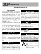
Suction
Line
Liquid
Line
Cap
Schrader
Valve
Figure 1. Suction & Liquid Line Locations

4
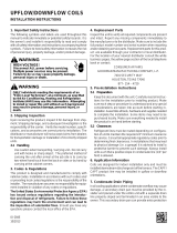
Figure2.LooseningofNut&DistributorBody
Figure4.RestrictorInsertionintoDistributorBody
Figure 3. Removal of Orifice
Connecting the Linesets
1.Route and cut both lineset tubes toproperlengthin
accordancewiththeoutdoorunitspecications.Verify
the ends are round, clean, and free of any burrs.
2. Connect the suction and liquid lineset tubes.
CAUTION:
It is recommended that a wet rag be wrapped
around the suction line in front of the close
off plate before applying heat. Failure to keep
components cool during brazing may result
in structural damage, premature equipment
failure, or possible personal injury.
3. Braze the individual connections with dry nitrogen
owing through the joints. This will prevent internal
oxidation and scaling from occurring.
4. Wrap the refrigerant lines with pressure sensitive
neoprene or other suitable material especially where
the lines enter the opening in the sheet metal.
Refrigerant Line Connections
System Depressurization
1.Removethecap(Figure1)fromtheendoftheliquid
line.
2.VerifypressurizationbydepressingtheSchradervalve
on the end of the liquid line. Listen for any escaping
gas. If there is no pressure, test the coil for leakage.
• Ifleakageisfound,clearlymarkthelocationoftheleak
and return the coil to the distributor for processing.
• Ifnoleaksarefound,thecoilmaybeinstalled.
3. Depress the valve to relieve all pressure from the coil.
4. Remove and discard the valve core and valve core
holder on the liquid line.
5.Removetherubberplugfromthesuctionline.
OriceRemoval&Installation
NOTE: Before proceeding, perform steps 1 - 3 in the
System Depressurization section and confirm that the
restrictor orifice size meets the requirements outlined in
the outdoor unit installation manual.
FactorysuppliedoricesizesarelistedinTable2(page
7).Iftheoricemustbereplaced,followsteps1-5.
CAUTION:
To prevent damage to the unit or internal
components, it is recommended that two
wrenches be used when loosening or tightening
nuts. Do not over tighten!
1.Usingtwowrenches,loosenthenutanddistributorbody
asshowninFigure2.Turntheassemblynutcounter-
clock-wise until the orifice body halves are seperated.
2. Insert a light-gauge wire hook between the distributor
body and the restrictor orifice while being careful not
to scratch either part. Carefully remove the restrictor
oricefromthedistributorbody.SeeFigure3.
3.Checkthe actual sizeof theneworice.Thesizeis
stamped on its side. Do not use pin gauges to measure
the orifice diameter.
4. Insert the new orifice into the distributor body, rounded
enddown.SeeFigure4
CAUTION:
To prevent damage to the unit or internal
components, it is recommended that two
wrenches be used when loosening or tightening
nuts. Do not over tighten!
5.Realigntheassemblynutonthedistributorbodyand
hand tighten both components. Mark a line on both
bodiesandthentightenanadditional1/4turnusingtwo
wrenches.Themovementofthetwolineswillshowhow
much the nut is tightened. If a torque wrench is used,
tightento10-12ft.lbs.or14-16Nm.

5
Condensate Drain
CAUTION:
The coil must be level to ensure proper
condensate drainage. Improper condensate
disposal may result in structural damage,
premature equipment failure, or possible
personal injury.
• Methodsfordisposingofcondensatevaryaccording
to local codes. Refer to local codes or authority having
jurisidiction for restrictions and proper condensate
disposal requirements.
• Allcondensatepanshaveprimaryandsecondarydrain
connectionstomeetFHArequirements.Iftheapplication
is located in or above a living space where damage
mayresultfromcondensateoverow,aseparate3/4
inch drain must be provided from the secondary drain
connection and a secondary drain pan must be installed
under the entire unit. Run secondary drain lines to a
place where they are noticeable if used.
• Thecoilcondensatepanisdesignedwith3/4”NPSC
drainconnections.UseaPVCorsimilarmaterialtting
to attach the drain line to the pan. NOTE:Thetting
should be hand tightened only. Overtightening may
crack the drain pan and cause condensate to leak.
• The drain pan MUST be drained with eld supplied
tubingorPVCpipeandadequatelytrapped.
IMPORTANT: Failure to install a trap may result in
condensation overflowing the drain pan, resulting
in substantial water damage to surrounding area.
• Primethetrapwithwater.Insulatethedrainifitislocated
in an unconditioned space, and test the condensate line
for leaks. Consult local codes for additional restrictions
or precautions.
• Routethelinestoasuitabledrain,avoidingsharpbends
andpinchingofthelines.Thedrainshouldmaintaina
minimum horizontal slope in the direction of discharge
ofnolessthan1”verticalforevery10ftofhorizontal
run.
• During system checkout, inspect the drain line and
connections to verify proper condensate drainage.
MAINTENANCE & SERVICE
WARNING:
ELECTRICAL SHOCK, FIRE OR EXPLOSION
HAZARD
Failure to follow safety warnings exactly could
result in serious injury or property damage.
Improper servicing could result in dangerous
operation, serious injury, death or property
damage.
• Before servicing, disconnect all electrical
power to the furnace or air handler.
• Whenservicingcontrols,labelallwiresprior
to disconnecting. Reconnect wires correctly.
• Verifyproperoperationafterservicing.
CAUTION:
Do not operate the system without a suitable
filter in the return air duct system. Always
replace the filter with the same size and type.
Toensureoptimumperformanceandtominimizepossible
equipment failure, the following maintenance tasks should
be performed periodically on this equipment:
1.Theairlterinstalledwiththesystemshouldbechecked
and cleaned or replaced twice per year.
2. Check the coil, drain pan, and condensate drain line
for cleanliness at the start of each heating and cooling
season. Clean as needed.
5.Evacuatethesystemofmoistureandnon-condensables
to prevent low efficiency operation or damage to the
unit.Thesuggestedrangeofevacuationis250-500
microns.
6.Chargethesystemwithrefrigerant.Please Refer to
the outdoor unit installation manual for additional
charging instructions.
7.Checkthesystemforleaks,includingthelinesetandthe
brazed joints. NOTE: Apply a soap and water solution on
each joint or union with a small paintbrush. If bubbling
is observed, the connection is not adequately sealed.
8. Properly dispose of all removed parts.
Air Filter
Air filters are not supplied as an integral part of this coil;
however, a filter must be installed upstream of the coil and
inspected frequently. When the filter becomes clogged
with dust or lint, it should be replaced (disposable type)
or cleaned (washable type). It is recommended that filters
be inspected and replaced at least twice during the year.
Generally it is best to replace or clean the filters at the
start of each heating and cooling season.

6
COIL SPECIFICATIONS & DIMENSIONS
Table 1. Coil Specifications
C5BA-
O24U-A O25U-A O30U-A O24U-B O25U-B O36U-B O48U-B O48U-C O60U-C
919131D 919132D 919133D 919134D 919135D 919137D 919139D 919140D 919142D
NominalCapacity,
Min(BTUH)
24,000 24,000 30,000 24,000 24,000 30,000 36,000 48,000 48,000
NominalCapacity,
Max(BTUH)
24,000 24,000 30,000 24,000 24,000 36,000 48,000 48,000 60,000
NominalAirow,
Min(CFM)
800 800 1,000 800 800 1,000 1,200 1,600 1,600
NominalAirow,
Max(CFM)
800 800 1,000 800 800 1,200 1,600 1,600 2,000
W - Width (in.) 123/4 123/4 123/4 181/8 181/8 181/8 181/8 21 21
H-Height(in.) 19 19 19 19 19 19 25 25 283/4
Connection -
Liquid Line (in.)
3/8 3/8 3/8 3/8 3/8 3/8 3/8 3/8 3/8
Connection -
Suction Line (in.)
3/4 3/4 3/4 3/4 3/4 3/4 7/8 7/8 7/8
NOTES:
(1)RefertosalesspecicationsheetsforListed/Certiedcombinationsofequipmentandrequiredaccessories.
(2)RefertothecurrentAHRIdirectoryforcertiedratingsofsplitsystems.
(3)Basedonanominal0.3”W.C.pressuredropacrossthecoil.
(4)TXVvalvemayberequiredtoachieveAHRIrating.
Figure 5. Coil Dimensions
W
2 1/2"
W
H
2 3/8"
19 1/2"
14 1/2"
12 1/8"
1 3/8"

7
FACTORYINSTALLEDORIFICEVS.FLEXIBLECOILPLUSORIFICE
Factory Installed
Orifice
Uncased
SKU
Cased
SKU
Horiz.
SKU
Flex Coil
Horiz.
Kit
CoilsMadeBefore
Aug. 1, 2009
Coils Made After
Aug. 1, 2009
Model SKU
Installed
Orifice
Supplied
Orifice
Installed
Orifice
Supplied
Orifice
C5B(A,H)-O24(U,C)-A 919131D 919143D 919155D C5BA-O24U-A 919131D 919318 0.050 - 0.055 0.050
C5B(A,H)-O25(U,C)-A 919132D 919144D 919156D C5BA-O25U-A 919132D 919318 0.060 0.053 0.061 0.053
C5B(A,H)-O30(U,C)-A 919133D 919145D 919157D C5BA-O30U-A 919133D 919318 0.065 - 0.065 0.061
C5B(A,H)-O24(U,C)-B 919134D 919146D 919158D C5BA-O24U-B 919134D 919318 0.050 - 0.055 0.050
C5B(A,H)-O25(U,C)-B 919135D 919147D 919159D C5BA-O25U-B 919135D 919318 0.060 0.053 0.061 -
C5B(A,H)-O30(U,C)-B 919136D 919148D 919160D
C5BA-O36U-B 919137D 919318
0.065
0.075
- 0.073 0.065
C5B(A,H)-O36(U,C)-B 919137D 919149D 919161D
C5B(A,H)-O37(U,C)-B 919425D 919426D 919427D
C5BA-O48U-B 919139D 919319
0.075
0.078
- 0.089 0.078
C5B(A,H)-O41(U,C)-B 919496D 919497D 919498D
C5B(A,H)-O42(U,C)-B 919138D 919150D 919162D
C5B(A,H)-O43(U,C)-B 919502D 919503D 919504D
C5B(A,H)-O48(U,C)-B 919139D 919151D 919163D
C5B(A,H)-O48(U,C)-C 919140D 919152D 919164D C5BA-O48U-C 919140D 919319 0.089 - 0.080 0.090
C5B(A,H)-O49(U,C)-C 919141D 919153D 919165D
C5BA-O60U-C 919142D 919320 0.089 0.099 0.089 0.099
C5B(A,H)-O60(U,C)-C 919142D 919154D 919166D
NOTES:
1.Individualrestrictorsareavailablebypartnumber-PN664***(where***representsthesize).Example:664103isarestrictor0.103indiameter.
2.InstalledoricesaresizedformostcommonR-410a13SEERmatches.Alwaysconsultoutdoorunitdocumentationforvericationoforicesize.
3.Dependingonapplication,additionalinstaller-suppliedoriceorTXVmayberequired.
Table 2. Orifice Sizes

CROSSREFERENCE:FACTORYINSTALLEDTXVVS.FLEXIBLECOILPLUSTXVKIT
Factory Installed
TXV Coil
Uncased
SKU
Cased
SKU
Horiz.
SKU
Flex Coil
Horiz.
Kit
TXV Kit
PN
Model SKU
C5B(A,H)-T24(U,C)-A 919167D 919179D 919191D C5BA-O24U-A 919131D 919318 920662
C5B(A,H)-T25(U,C)-A 919168D 919180D 919192D C5BA-O25U-A 919132D 919318 920662
C5B(A,H)-T30(U,C)-A 919169D 919181D 919193D C5BA-O30U-A 919133D 919318 920663
C5B(A,H)-T24(U,C)-B 919170D 919182D 919194D C5BA-O24U-B 919134D 919318 920662
C5B(A,H)-T25(U,C)-B 919171D 919183D 919195D C5BA-O25U-B 919135D 919318 920662
C5B(A,H)-T30(U,C)-B 919172D 919184D 919196D C5BA-O36U-B 919137D 919318 920663
C5B(A,H)-T36(U,C)-B 919173D 919185D 919197D C5BA-O36U-B 919137D 919318 920664
C5B(A,H)-T37(U,C)-B 919428D 919429D 919430D C5BA-O48U-B 919139D 919319 920664
C5B(A,H)-T41(U,C)-B 919499D 919500D 919501D C5BA-O48U-B 919139D 919319 920665
C5B(A,H)-T42(U,C)-B 919174D 919186D 919198D C5BA-O48U-B 919139D 919319 920665
C5B(A,H)-T43(U,C)-B 919505D 919506D 919507D C5BA-O48U-B 919139D 919319 920665
C5B(A,H)-T48(U,C)-B 919175D 919187D 919199D C5BA-O48U-B 919139D 919319 920666
C5B(A,H)-T48(U,C)-C 919176D 919188D 919200D C5BA-O48U-C 919140D 919319 920666
C5B(A,H)-T49(U,C)-C 919177D 919189D 919201D C5BA-O60U-C 919142D 919320 920666
C5B(A,H)-T60(U,C)-C 919178D 919190D 919202D C5BA-O60U-C 919142D 919320 920667
Table 3. C5 Coil with R22 Refrigerant
CROSSREFERENCE:FACTORYINSTALLEDTXVVS.FLEXIBLECOILPLUSTXVKIT
Factory Installed
TXV Coil
Uncased
SKU
Cased
SKU
Horiz.
SKU
Flex Coil
Horiz.
Kit
TXV Kit
PN
Model SKU
C5B(A,H)-X24(U,C)-A 919509D 919612D 919203D C5BA-O24U-A 919131D 919318 920668
C5B(A,H)-X25(U,C)-A 919626D 919613D 919625D C5BA-O25U-A 919132D 919318 920668
C5B(A,H)-X30(U,C)-A 919510D 919614D 919204D C5BA-O30U-A 919133D 919318 920669
C5B(A,H)-X36(U,C)-A 919679D 919678D 919680D C5BA-O30U-A 919133D 919318 920670
C5B(A,H)-X24(U,C)-B 919511D 919615D 919205D C5BA-O24U-B 919134D 919318 920668
C5B(A,H)-X25(U,C)-B 919628D 919616D 919627D C5BA-O25U-B 919135D 919318 920668
C5B(A,H)-X30(U,C)-B 919512D 919617D 919206D C5BA-O36U-B 919137D 919318 920669
C5B(A,H)-X36(U,C)-B 919513D 919618D 919207D C5BA-O36U-B 919137D 919318 920670
C5B(A,H)-X37(U,C)-B 919630D 919619D 919629D C5BA-O48U-B 919139D 919319 920670
C5B(A,H)-X42(U,C)-B 919514D 919620D 919208D C5BA-O48U-B 919139D 919319 920671
C5B(A,H)-X48(U,C)-B 919515D 919621D 919209D C5BA-O48U-B 919139D 919319 920672
C5B(A,H)-X48(U,C)-C 919516D 919622D 919210D C5BA-O48U-C 919140D 919319 920672
C5B(A,H)-X49(U,C)-C 919517D 919623D 919211D C5BA-O60U-C 919142D 919320 920672
C5B(A,H)-X60(U,C)-C 919518D 919624D 919212D C5BA-O60U-C 919142D 919320 920673
Table 4. C5 Coil with R410A Refrigerant
708705C (Replaces708705B)
Specications&illustrationssubjecttochangewithoutnoticeorincurringobligations(05/15).
O’Fallon,MO,©NortekGlobalHVACLLC2015.AllRightsReserved.
/