
50GL
SingMe-Packaged 50 Hz, CE EMectric CooMing Units
with Puron® (R-410A) Refrigerant
%isitwww.camer.com
A Guide to Operating and Maintaining Your
Singme-Packaged Emectric Cooming Units
NFATUNG & COOLING
NOTE: Read the entire instruction manual before starting the
installation.
SAFETY CONSIDERATIONS
Note to Installer:This manual should be left with the equipment
user.
Do not store or use gasoline or other flamnmble w_pors and
liquids in the vicinity of these or any other appliances. Failure
to follow this warning could result in fire, serious injury, or
death.
Do not use this unit if any part has been under water
Immediately call a qualified service technician to inspect the
unit and to replace any part of the control system which has
been under water. Failure to follow this warning could result
in electrical shock, fir< serious injury, or death.
Befbre per_brming recomnrended maintenanc< be sure the
main power switch to unit is turned off and lockout tag
installed Electric shock could cause serious it{jury or death.
STARTING OR SHUTTING UNmT OFF
1. To start this unit:
a. Turn on the electrical power supply to unit.
b. Select temperature and set SYSTEM switch or MODE
control to desired mode.
2. To shut this unit off:
NOTE: If the unit is being shut down because of a malNnction,
call your dealer as soon as possible.
a. Set system SWITCH or MODE contlol to OFF.
b. Turn off the electrical power supply to unit and install
lockout tag.
OPERATING YOUR ELECTRIC AmR CONDITmONER
The operation of'your system is conholled by the indoor thermo-
stat. You simply adjust the thermostat and it maintains the indoor
temperature at the level you select. Most themaostats have 3
controls: a temperature control selector, a FAN control, and a
SYSTEM or MODE control. RefEr to your thermostat owner's
manual for more infbrmation.
To better protect your investment and to eliminate unnecessa_
sela'ice calls, familiarize yourself with the %llowing g_cts:
Step l--Cooling Mode
With the SYSTEM or MODE control set to COOL, your unit will
run in cooling mode until the indoor temperatore is lowered to the
level you have selected. On extlemely hot days, your system will
run for longer periods at a time and have shorter "oft" periods than
on moderate days.
Fig. 1--Unit 80GL (80Hz)
C99064
Step 2--Heating Mode (with optional electric heaters)
Your system may have optional electric heaters for use when
heating is desired.
With the SYSTEM or MODE control of your indoor thermostat set
to HEAT, your unit will rnn in heating mode until room tempera°
rare is raised to the level you have selected. Of course, your systenr
will run fbr longer periods to maintain a comfortable environment
on cooler days and nights than on moderate ones.
MAINTENANCE AND SERVmCE
This section discusses maintenance that should be per%treed by
your dealer.
ROUTINE MAINTENAN< E
All routine maintenance should be handled by skilled, experienced
personnel Your dealer can help you establish a standard proce°
dure
For your safety, keep your unit area clear and thee of combustible
materials, gasolin< and other flammable liquids and vapors.
To assure proper ffinctioning of your unit, flow of condenser air
must not be obstructed [i'om reaching the unit Clearance fi'om dae
top of the unit is 36 in (914 ram). ( learance of at least 42 in. (1070
ram) is required on sides, except the duct side which has a 12 im
(305 ram) minimum clearance
MAINTENANCE AND <7ARE BY THE EQUIPMENT OVv_ER
Befbre proceeding with those things you might want to maintain
yourself, please careffilly consider the fbllo_ing:
Manufacturer reserves the right to discontinue, or change at any time, specifications or designs without notice and without incurring obligations.
PC 101 Catalog No 005-00012 Printed in USA. Form OM50-C1 Pg 1 01-02 Replaces: New

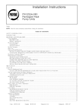
FILTER ACCESS
PANEL*
ACCESS PANEL
*For accessory fitterrack.
Table I--Indoor-Air FHter Data
C99094
UNIT SIZE
50GL 024 030 036 048 060
(50 NZ)
RETURN=A_R
20" x 20" xl" 20" x 20" x 1" 20" x 24" x 1" 24" x 30" x 1" 24"x 30"x 1'
FILTER (mm / (508 x 508 x 251 (508 x 508 x 25) (508 x 609.6 x 25) (609.6 x 762 x 251 (609.6 x 762 x 25)
Throwaway
Fig. 2--Filter Access PaneloVertica! Supply Shown
1. TERN OFF ELE(TRICAL POWER TO YOUR ENIT
BEFORE SERVI(ING OR PERFORMING MAINTE-
NAN(E. ELECTRI( SHOCK (OULD CAUSE SERI-
OtIS INJURY OR DEATH.
2. When removing access panels or perfbm_ing maintenance
fimctions inside your unit, be aware of sharp sheet metal
parts and screws. Although special care is taken to keep
sharp edges to a minimum, be extremely carefifl when
handling parts or reaching into the unit.
Air Filters
The air filter(s) should be checked about eve N- 4 weeks and
changed or cleaned whenever it becomes dirty Dirty filters
produce excessive stress on the blower motor and can cause the
motor to overheat and shut down. Table 1 indicates the correct
filter size for your unit Refer to Fig 2 to access the filters
To replace or inspect filters (or accessory filter rack when
supplied):
1. Remove the filter access panel using a 5/16oin (7.9 ram) nut
&iver or wrench.
2. Remove the filter(s) by pulling it out of the unit. If the filter(s)
is dirty-, clean or replace with a new one.
When installing the new filter(s), note the direction of the airflow
arrows on the filter fi'ame.
If you have difficulty locating your air filter(s) or have questions
concerning proper filter maintenance, contact your dealer for
instructions. When replacing filters, always use the same size and
type of filter that was supplied, originally, by the installer.
Neveroperate your unit without the filter(s) in place. Failure
to heed this warning may result in damage to the blower
motor and/or compressor An accumulation of dust and tint on
internal parts of your unit can cause loss of eft]ciency and, in
some cases, a fire.
Fans and Fan Motor
Periodically, check the condition of _Sn wheels and honsings and
fanomotor shall bearings. (ontact your dealer for the required
annual maintenance.
Indoor and Outdoor (?oils
(?leaning of the coils should only be done by qualified service
personnel. Contact your dealer for the required annual mainteo
nance.
Condensate Drain
The &ain pan and condensate drain line should be checked and
cleaned at the same time the cooling coils are checked by your
dealer.
Compressor
All compressors are factov-shipped with a normal charge of fl_e
con'ect type refi'igeration grade oil. A compressor should rarely
require additional oil.
Condenser Fan
Do not poke sticks, screwdrivers, or any other ok_iects into
revolving fan blades. Injury or equipment damage may result.
The fire retest be kept free of all obstructions to ensure proper
cooling Contact your dealer for any required service.

Electrical Controls and Wiring
Electrical contwls are dKiicult to check without proper instrumen=
rations. If there are any discrepancies in the operating cycle,
contact your dealer and request service
Refi'igerant Circuit
The rel:i'igerant circuit is difficult to check for leaks without the
proper equipment. If inadequate cooling is suspected, contact your
tocal dealer %r service.
System under pressure. Relieve pressure and recover all
refi'igerant before system repair or final unit disposal to avoid
serious injury or death. Use all service ports and open all
flow°control devices, including solenoid valves.
Unit Panels
After per%m_ing any maintenance or service on either of these
units, be sure all panels are l:i_stened securely in place to prevent
rain from entering unit cabinet and to prevent disr_/ption of the
correct unit airflow pattern
REGULAR DEALER MAINTENAN(E
In addition to the type of routine maintenance you might be willing
to perform, your unit should be inspected regularly by a properly
trained service technician. An inspection (preferably each year, but
at least eve N" other year) should include the following:
1. Inspection and, if required, cleaning of the outdoor and indoor
coils.
2. Inspection and, if required, cleaning of the indoor coil &ain
pan.
3. Inspection and cleaning of blower wheel housing and motor.
4. Inspection of all supply°air and return-air ducts %r leaks,
obstructions, and insulation integrity. Any problems _bund
should be resolved at this time.
5. Inspection of the unit base to ensure that no cracks, gaps, etc.,
exist which may cause a hazardous condition.
6. Inspection of the unit casing %r signs of deterioration.
7. Inspection of all electrical wiring and components to assure
proper connection.
8. Inspection %r leaks in the refrigerant circuit. Pressure-check
to determine appropriate refrigerant charge.
9 Operational check of the unit to determine working condi-
tions Repair or a4iustment should be made at this time
Your sela'icing dealer may offer an economical service contract
that covers seasonal inspections Ask for fiu_ther details
Complete service instructions can be found in each unit's Instal-
lation, Start=Up and Service Instructions
BEFORE YOU (ALL FOR SERVICE ...
...check %r several easily-solved problems.
If insufficient cooling is suspected:
( ) Check for suKicient airflow. Check the air filter for dirt. Check
for blocked return=air or supply-air grilles. Be sure they are open
and unobstlucted. If these checks do not reveal the cause, call your
servicing dealer.
If your unit is not operating at all, check the %llowing list %r
easy solutions:
( ) (beck to be sure that your thermostat temperature selector is set
below the indoor temperature during the cooling season or above
the indoor temperatnre during heating season (if unit is installed
with optional electric heater). Be sure the SYSTEM switch or
MODE control is in the COOL or HEAT position and not in the
OFF position.
( ) If your unit still tilils to operate, call your servicing dealer %r
tloubleshooting and repairs. Specii}' the model and serial numbers
of your unit. (Record them in this manual in the space provided.)
If the dealer knows exactly which unit you have, he may be able
to oflkr suggestions over the phone, or save valuable time through
knowledgeable preparation ibr the sela'ice call.
IN (ASE OF TROUBLE
If you per%tin the steps above and unit per%rmance is still
unsatisfactory, shut off the unit and call your dealer.
Dealer's Name
Telephone
Unit Model
Unit Serial Number

Copyright 2002 CARRIER Corp. _ 7310 W. Morris St • Indianapolis, IN 46231 om50cl
Manufacturer reserves the right to discontinue, or change at any time, specifications or designs without notice and without incurring obligations,
B°°kLL_. PC 101 Catalog No 005-00012 Printed in U.S.A. Form OM50-C1 Pg 4 01-02 Replaces: New
Tab 16al 8a
-
 1
1
-
 2
2
-
 3
3
-
 4
4


Carrier 50GL030310 Owner's manual
- Type
- Owner's manual
- This manual is also suitable for
Ask a question and I''ll find the answer in the document
Finding information in a document is now easier with AI
Related papers
-
Carrier 50GL-A User manual
-
Carrier 50GL-A Owner's manual
-
Carrier 50GS024300 Owner's manual
-
Carrier 48XP036060300 Owner's manual
-
Carrier 50JZ048 User manual
-
-
-
-
Carrier 50JZ048300 Owner's manual
-
Carrier 50GS024300 Installation guide
Other documents
-
Bryant 704B User manual
-
 Payne PA13 Owner's manual
-
Costway CM22052 Operating instructions
-
-
 Payne PN1Z060 Installation guide
-
Payne PY2PNB060090AA Owner's manual
-
 Payne PH2PNB036000AA Installation guide
-
-
Trane 4TWR3 Installer's Manual
-
Rheem RKKL-B240CM40EAJA Installation guide


