
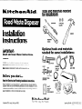
Tools and materials needed
for installation:
Installation
Instructions
iMPORTANT:
Read and save these instructions.
IMPORTANT:
Installer: Leave Installation Instructions with the homeowner.
Homeowner: Keep Installation Instructions for future reference
Save Installation Instructions for local electrical inspector’s use.
’ Before you start...
Read the Electrical and Plumbing Installation Instructions.
Proper installation is your responsibility. A qualified technician should install this
disposer. Make sure you have everything necessary for correct installation. It is the
customer’s responsibility to contact qualified electrical and plumbing Installers to
assure installation is correct and meets all local codes.
KItchenAId,@ St. Joseph, Michigan 49085
2 wire nuts
Optional tools and materials
needed for some installations:
- - pipe wrench
coupler ,
connector
dishwasher drain
strain relief
UttchenAid”
For the way it’s made.
hack saw
FormNo./PartNo. 70309/4211562
__---
_

3
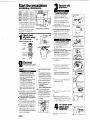
Remove old
disposer.
Start the installation
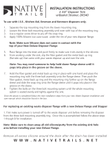
Installation dimensions
Garbage Disposer Dimensions
ELECTRICAL SHOClt HAURD
Drsconnect from electrrcal supply
Mure to do so could result rn
electrm shock, personal rnyry, or
de&
Compare your ne.v drsposer mounting
assembly’wh the exrsring mounting
If the rnou, rtrng assemblres are the same,
complete Steps 3-A, B, D, E
A Using a pope wrench, disconnect the dram
hne where rt attaches to the drsposerwaste
line prpe
B.
If old disposer mounting is the same as
your new one, Insert end of Jam-breaker
wench or screwdrrver Into rrght srde of a
d,sposer mountrng nng lug at top Of
d,sposer Hold drsposer wth other hand
Turn jam-breaker wench or screwdrrver
counterclochse untd lug hnes up wrth one
of the srnk-mounting assembly scrw6
B’ - Drstance from bottom of srnk to center
tine Of drsposeroutlet Add l/g inch whe
stainless steel srnk IS used.
C’ - Length of waste lrne proe from center
he of d;poser outlet to end of waste lrne
we
IMPORTANT Plumb waste lrne to prevent
standrng water I” the drsposer motor
housrng
1
Check that
all parts were
included.
Drawing show just one model type.
tmng to prevent It from fallmg when
the mountrng nng rs drsconnected.
Farlure to do x) could result rn damage
Remove drsposer Go to Step 3-D
C. If old disposer mounting is different from
your new one, remove the nuts on the
mountmg nry ~“3 plrers or an adjustable
wench Remove old drsposer You may
need to remove a clamp or h-w the
drsposer to remove It
D.Turn drsposer upsrde down and remove the
electrIcal plate
2
Electrical
requirements
E. Use a screwdrrver IO remove the groundrng
wire Remove wire nuts from power
w,res Separate drsposer power w,reS
from the cable wares Loosen screw(s)
on strafr relref and remove cable horn the
drsposer
If old disposer mounting is the same
as your new disposer mOunting, go to
SWP 5.
Electrical ground is mqulnd on this
E.
AU L.-listed conduct connector
applbnce.
must be prwrded at Uw runchon
box
F.
It
IS the
persona responsibrlrh,
ELECTRICAL SHOCK HAZARD
l
Electrical ground IS requrred on ttxs
appliance
l
Improper connechon of the equrpment-
groundmg conductor can result I”
elecmcal shock
*Check wth a qualrfred electncran rf you
are rn doubt as to whether the
applrance IS properly grounded
l
Do Not have a fuse rn the neutral or
groundmg crrcurt A fuse rn the neutral
M groundmg orcurt could result rn
elecmcal shock.
and oblrgatron of the customer to
contact a qualrfred electncran to
assure that me electrical rmtallahon
IS adequate and IS rn conformance
wlm me Natronal Electrrcal code
ANWNFPA 7@latest edrtron’ and
all local codes and wdrnances
Copies of the standards lrsted
may be obtwred from
* National Fire Protection
Arsociation
Batterymarch park
Ouincy, Massachusettr OF269
G.Fw contmuous feed models
Install a 15. or PO-amp wall
swatch above the countenop and
junction box rnsrde cabrnet as
shown (watch and electrrcal
wrrrng can be obtamed locally )
PosItron swtch I” a convenrent
locatIon Connect wrtch to
]uncOo” box
F. loosen screw and remove the mounrrng
ring and back-up rungs A hammer may be
needed to loosen rrngs
Farlure to follow these rnstructrons could
result rn a hre, electrical shock cx omer
o+?rslYa rnruw
G. Push old smk sleeve up rhrough the sink hole
and rerno”e
A.
120 Volt, 60 Hz. AC only, 15 or 20 Ampere
fused electrical supply 1s requrred. (Time-
delay fuse or crrcurt breaker IS recommended.)
It IS recommended mat a separate crrcurt
serwrg only thus applrance be prowded
8.
THE DISPOSER MUST BE CONNECTED WlTH
COPPER WlRE ONLY.
H.Clean sealant from srnk hole rrm usrng a
screwdrwer or putty knife [o scrape away all
traces of putty or caulkrng from the sink hole
r,m Hole rim must be as clean as posirble
for a good. watenrght seal
C. We srzes and connectrons must conform
to the requrrements of the NatIona Elecmcal
Code, ANSI/NFPA 70latest edrtron’ and all
local codes and ordrrrances.
D.Thrs applrance should be connected to the
fused-drsconnect (or crrcurt breaker) box
through flexrble, armored or nonmetallic
shearned, copper cable (wrth groundrng
wrre) The flexible amxued cable extendrng
from the applrance should be connected
directly to the ~unctron box
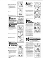
4
To install our
sink’s firs
r
disposer :
A-Use wench to ioosen nut at fop of
“P”-trao
PANEL A

8. Remove nut at top of smk strajner Remove
extenslo” pipe
C.
Loosen the large-diameter nut at the base
of rhe strainer by placlng the tip of a
screwdriver on rhe ridge of the nut and
gently rappIng [he scrwdwer with a
hammer
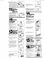
8
Attach the
upper
mounfiqg
assembhi.
A Working from under sink, slip the &ond
rubber gasket, then the metal back-up ring
(flat side up), up and over sink flange
D. Remove nut
E.
Push the strainer assembly up through the
sink hole and remove
5
Clean sink’s
drain line.
If installing m a new home, go to Step 6.
Remove dram trap. U&ng an auger. clean out
the howont. drain pope that runs from the
trap to the ma,” waste pope.
6
Separate the
mounting
assembly.
A
Holdmg rhe mcuntlng assemblywth one-
hand, use the other hand to ~nsenjam-
breaker wench Into one of the lugs of the
lower mounting ring Turn assembly counter-
clockwise and rerno4.
B. Loosen screw-i on mount,ng assembly until
they are lwel wth mou”t,ng ring surface
c. Use screwdriver to pry off snap r,ng
D.
Take assembly apart and set aslde
7
Apply rubber
s
asket or putty
o sink flange. ,-,
A The rubber sink flange gasket should always
be used where powble Place rubber
gasket over sink flange Go to Step J-C
B. If sink opening does not pemxt the use of a
rubber seal. plurhber’s putty may be used
Form puty Into a long roll by rolllng It
between your hands Press roll under sink
flange r\m
c. Place flange Into sink drain hole Push down
genrly but firmIx to make sure flange SltS
evenly over gasket cn in purry
PANEL B
a. Holding [he rubber gasket and metal back-
up r,“g I” place, atlach the mo”nt,“g r,“g to
the sleeve with the three mounting ring
scr- Do Not rIghten scre*ys at thts tome
C. Push rubber gasket, metal back-up ring and
mo”nt,“g mg funher up sink slewe Slide
snap ring onto sink slewe until It pops Into
place I” the sleeve groove
D.T~ghten mount,ng SC,- until entlre
moumng assembly IS seated evenly and
tightly agamst sink
D.
9
Make
electrical
connections.
A Remove elecmcal plate from the bottom
of the “ewd~sposer Pull out the blackand
wtwe elecb~cal wres. Locate the green
grounding screw under plate
B. Insert strain relief mto hole Insert power
supply cable throuqh strain relief Pull cable
w,res rhrough ope&g where disposer
WIRS are located Tighten stral” relief
SClW.5
connect rhi to white, and black to
I
--rm
black. wrap wire ConnectIons wlrn
elecmcal tape Put wres back inslde
disposer housIng Notez This appliance 15
equlpwd wlt3? copper lead wires If
connectlo” 1s made to aluminum house
wmng, use only speoal connectors wixch
are approved for,o,nmg copper to
alumrum wires I” accordance with tie
natlonal electrical code and local codes
and ora~nances
Improper COnneCtlon of the equlpment~grcundlng conducta
!
can result w electrical shock. oer~~l ~nfuw o( &am
:
Electrical ground is required on this
appliance.
‘90 NOT reconnect electrical current to
main service panel until proper ground
IS r.sMled.
A.lf the cabls leading to the disposer has
three wires, attach the green grounding
wire to the green grounding screw Go to
S’ep 10-D

G. If drain is too short, measure how far
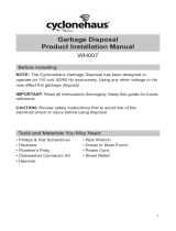
D. Check to see If you have a water meter in
your home To have a grwnded water pope,
the meter must have a wire clamp to either
side of the meter You can ground the water
pipe by securely clampmg a length of NO 6
copper we for 900 amp sewce (or less) to
bare metal as show Use grcundlng clamps,
certlfled by U.L., to attxh wre to pipe.
trap outlet IS from rub+? and buva drain trap
extensnn with a slop nut Install rrap
exrensm
H. When it fits, tIghten the SIID nut on the trap
For double smks, we recommend use of
separate traps for disposer and second
sink.
11
0.ptional
i;shrsher
connection
If you do not plan to connect a
dishwasher drain to the disposer, go to
Step 12.
Lay dqcner on Its side Insert tip of
xre*vdrner at an angle Into drain hole
opening Tap screwdriver wth hammer until
molded plug pops out Remove loose plug
from dqoser
14
OWional:
Connect tb
dishwasher drain.
If you do not plan to connect a
dishwasher drain to the disposer, go
to Step 15.
Make sure connections comply with
local plumbing codes.
A. A dishwasher drain connector kit may be
purchased from a hardware store Use worm
gear hose clamp on dlshwasherconnectlon
Remove clamp cn fltnng from end of
dishwasher drain hose
12
Connect
disposer
to mounting
assembly.
A
Lift the dIsposerand posIton It so that the
dtsposer3 three mounting ears are lined up
under the ends of the sink mounting
assembly screws
6. Holding the drsposer in place, turn the
lower mounting ring with ears to the right
until all three ears lock Into place in the
mounting assembly The disposer WIII now
hang by Itself The mounting ring v-111 be
locked in place later
3.8 #de large end of rubber couplerover
disposer Inlet tube Fasten coupler to
disposer uilth clamp provided
13
Attach the
disposer
waste line
pipe to drain trap.
C. Insert one end of the plastlc tube Into the
coupler and fasten w[h /a” clan13
A. Remove any foreign materials that may
have dropped InsIde the disposer gwdlng
chamber
D. Slip the gear hose clamp over the
dIshwasher drain hose pushing
It
back P-3
inChes Slop drain hose over plastlc tube
Slfde ciamo I” place and tIghten
Be sure to tiyhten all three clamPS.
8. Turn the disposer around Compare your
disposer waste line pipe with the hvo types
iliustrated in C and D Attach waste line
pipe as speclfled
C. If not aIre@ assembled, place the gasket
over the end of waste line pipe Gasket must
be installed as shown to prevent leakIng
Insert tube rxo disposer opening Place
flange over waste line pipe and gasket
Secure flange to disposer with screw
provided
D. Insert the gasket Into the disposer dlschdrge
outlet Gasket WIII be held in place by the
waste llne pipe flange Place flange over
waste line pipe Secure flange and waste
line pope to dIsposerwIth screwis)
provided
Insert scrworner or lam-breaker wrench
I/” f.w
I I
fnto left side of d asposer mounrlng lug
at rhe too of the aioow Turn screwdwer
orjam-breakerwench to right until
dwoser IS locked flrmlv I” olace
11
D.
operation.
A
S’owly run water !hrough unl! Then pidce
stopper seal in posItion and fill sink
0. Remove stopper and perml: water 10 flow
Check for leaks dl a11 olumblng connections
If there 1s a leak, rlgnten the ConnectIon at
trar pcmt
E. Rotate d&poser until waste line pipe alws
with drain trap
C. Turn on electrical power supply
D. Turn water on Run olspenser ror one minute
Check that disposer 1s opera:lng correctly
Check for leaks ar a’1 plumbing connections
agm If there IS a leak, tlghten the
~on”e~I10n dl !hal “01nI
Make sure all connections comply with
local plumbing codes.
F. lf tube is too long, ww off excess tublng
wth d ha&&v Mdke sure GUI IS Clean dna
straight
PANa c

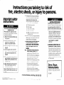
Instructions pertaining to risk of
fire, electric shock, or injury to persons.
,
01991 KItchenAId, Inc
bmNo./PartNo. 70309/4211562
Important safety
instructions:
ELECTRICAL SHOCK AND PERSONAL
INJURY HAZARD
When using electric appliances, basic
precautions should always be followed,
including the following:
1. Read all the instructions before using
the appliance.
2. To reduce the risk of injury, close
supervision is necessary when
appliance is used near children.
3. Do not put fingers or hands into waste
disposer.
4. Turn the power switch to the OFF
position before attempting to clear a
jam or remove an object from the
disposer.
5. When attempting to loosen a jam in a
waste disposer, use a self service jam-
breaker wrench as described in Use
and Care Guide.
6. When attempting to remove objects
from a waste disposer, use long-
handled tongs or pliers.
Failure to follow these instructions could
result in electrical shock, personal injury
or death.
7. To reduce the risk of injury by materials
that may be expelled by a food-waste
disposer, place the stopper in the
drain/grind position when grinding Do
not put the followrng into a disposer
a. Clam and oyster shells.
b. Drain cleaner,
c. Glass, chrna or plastic.
d. Large, whole bones
e. Metal, such as bottle caps, tin cans,
or alumrnum foil.
8. When not operating a disposer, leave the
drain
cover In place to reduce the nsk of
ObjeCtS
falling Into the disposer.
9. Refore pressing red reset button, be
sure the wall switch is in the off
position and on batch feed models
remove the stopper from the run
position.
10. a. GROUNDING INSTRUCTIONS FOR
CORD-CONNECTED UNITS. This
applrance must be grounded. In the
event of a malfunction or breakdown,
yroundrng provides a path of least
resrstance for electrtc current to
reduce the nsk of electnc shock If this
applrance
IS
equipped wtth a cord
having an equipment-grounding
conductor and a Qroundlng plug, the
plug must be plugged Into an
appropriate outlet that
IS
properly
Installed and yrounded In accordance
with all local codes and ordinances.
For service information, call toll-free l-800-422-1230
Prepared by KItchenAId,” St Joseph, Mlchlgan 49085
1
Electrical ground is required on this
;ECTRlCAL SHOCK ,ZARD 1
applrance. Improper connectron of the
equipment-grounding conductor can
result in a risk of electric shock or death.
Check with a qualified electrician or
serviceman if you are in doubt as to
whether the appliance is properly
grounded. Do not modify the plug - if
it will not fit the outlet, have a proper
outlet installed by a qualified
electrician.
b. GROUNDING INSTRUCTIONS FOR
PERMANENTLY CONNECTED UNITS:
This appliance must be connected to
a
grounded, metal, permanent wrnny
system; or an equrpment-grounding
conductor must be run with the circuit
conductors and connected to the
equipment-grounding terminal or lead
on the appliance.
Save these
instructions.
INSTALLER - Please leave Installation
Instructions with the homeowner or
occupant.
Pnnted In US A
-
 1
1
-
 2
2
-
 3
3
-
 4
4
-
 5
5


Ask a question and I''ll find the answer in the document
Finding information in a document is now easier with AI
Related papers
-
KitchenAid KCDI250X User manual
-
-
-
-
-
KitchenAid KCDC250X User manual
-
KitchenAid KBDS250 User manual
-
KitchenAid KWI200 Owner's manual
-
-
Other documents
-
 Drain Strain BRN 001 Installation guide
-
 Newport Brass 120/VB Installation guide
-
Newport Brass 121/10B Installation guide
-
Everbilt 21-DSFS3-BN User manual
-
InSinkErator FLG-BIS Installation guide
-
Whitehaus Collection WH202-HPOC Installation guide
-
 Whitehaus Collection WH202-ABRAS Installation guide
-
 Native Trails Kitchen & Bath DR340-PN Installation guide
-
Whirlpool GC2000 Installation guide
-
 Whitehaus Collection WH007-BN User manual


