Page is loading ...

Document. No. E1949E11 (Ver. 1.1)
Date Published September 2012 (K) Japan
Printed in Japan
URL: http://www.elpida.com
©Elpida Memory, Inc. 2012
PRELIMINARY DATA SHEET
COVER
Specifications
• Density: 1G bits
• Organization
— 16M words × 8 bits × 8 banks (EDJ1108EJBG)
— 8M words × 16 bits × 8 banks (EDJ1116EJBG)
• Package
— 78-ball FBGA (EDJ1108EJBG)
— 96-ball FBGA (EDJ1116EJBG)
— Lead-free (RoHS compliant) and Halogen-free
• Power supply: 1.35V (typ)
— VDD = 1.283V to 1.45V
— Backward compatible for VDD, VDDQ
= 1.5V ± 0.075V
• Data rate
— 1866Mbps/1600Mbps/1333Mbps (max)
• 1KB page size (EDJ1108EJBG)
— Row address: A0 to A13
— Column address: A0 to A9
• 2KB page size (EDJ1116EJBG)
— Row address: A0 to A12
— Column address: A0 to A9
• Eight internal banks for concurrent operation
• Burst length (BL): 8 and 4 with Burst Chop (BC)
• Burst type (BT):
— Sequential (8, 4 with BC)
— Interleave (8, 4 with BC)
• /CAS Latency (CL): 5, 6, 7, 8, 9, 10, 11, 13
• /CAS Write Latency (CWL): 5, 6, 7, 8, 9
• Precharge: auto precharge option for each burst
access
• Driver strength: RZQ/7, RZQ/6 (RZQ = 240Ω)
• Refresh: auto-refresh, self-refresh
• Refresh cycles
— Average refresh period
7.8µs at 0°C ≤ TC ≤ +85°C
3.9µs at +85°C < TC ≤ +95°C
• Operating case temperature range
— TC = 0°C to +95°C
Features
• Double-data-rate architecture: two data transfers per
clock cycle
• The high-speed data transfer is realized by the 8 bits
prefetch pipelined architecture
• Bi-directional differential data strobe (DQS and /DQS)
is transmitted/received with data for capturing data at
the receiver
• DQS is edge-aligned with data for READs; center-
aligned with data for WRITEs
• Differential clock inputs (CK and /CK)
• DLL aligns DQ and DQS transitions with CK transitions
• Commands entered on each positive CK edge; data
and data mask referenced to both edges of DQS
• Data mask (DM) for write data
• Posted /CAS by programmable additive latency for
better command and data bus efficiency
• On-Die Termination (ODT) for better signal quality
— Synchronous ODT
— Dynamic ODT
— Asynchronous ODT
• Multi Purpose Register (MPR) for pre-defined pattern
read out
• ZQ calibration for DQ drive and ODT
• /RESET pin for Power-up sequence and reset function
• SRT range:
— Normal/extended
• Programmable Output driver impedance control
• Seamless BL4 access with bank-grouping
— Applied only for DDR3-1333 and 1600
1G bits DDR3L SDRAM
EDJ1108EJBG (128M words × 8 bits)
EDJ1116EJBG (64M words × 16 bits)

EDJ1108EJBG, EDJ1116EJBG
Preliminary Data Sheet E1949E11 (Ver. 1.1)
2
Ordering Information
Note: 1. Please refer to the EDJ1108DJBG, EDJ1116DJBG datasheet (E1729E) when using this device at 1.5V operation, unless
stated otherwise.
Part Number
Operating Frequency
Detailed Information
For detailed electrical specification and further information, please refer to the DDR3L SDRAM General Functionality
and Electrical Condition data sheet (E1927E) and Addendum data sheet (E1928E).
Part number
Die
revision
Organization
(words × bits)
Internal
banks
JEDEC speed bin
(CL-tRCD-tRP) Package
EDJ1108EJBG-JS-F
EDJ1108EJBG-GN-F
EDJ1108EJBG-DJ-F
J 128M × 88
DDR3L-1866M (13-13-13)
DDR3L-1600K (11-11-11)
DDR3L-1333H (9-9-9)
78-ball FBGA
EDJ1116EJBG-JS-F
EDJ1116EJBG-GN-F
EDJ1116EJBG-DJ-F
J 64M × 16 8
DDR3L-1866M (13-13-13)
DDR3L-1600K (11-11-11)
DDR3L-1333H (9-9-9)
96-ball FBGA
Frequency (Mbps)
Speed
Grade CL5 CL6 CL7 CL8 CL9 CL10 CL11 CL13
speed bin
(CL-tRCD-tRP)
-JS 667 800 1066 1066 1333 1333 1600 1866
DDR3L-1866
(13-13-13)
-GN 667 800 1066 1066 1333 1333 1600
DDR3L-1600
(11-11-11)
-DJ 667 800 1066 1066 1333 1333
DDR3L-1333
(9-9-9)
Elpida Memory
Density / Bank
11: 1Gb / 8-bank
Organization
08: x8
16: x16
Power Supply
E:
,1.35V
Die Rev.
Package
BG: FBGA
Speed
Product Family
J: DDR3
Type
D: Packaged Device
E D J 11 08 E J BG - JS - F
Environment code
F: Lead Free (RoHS compliant)
and Halogen Free
JS: DDR3-1866M (13-13-13)
GN: DDR3-1600K (11-11-11)
DJ: DDR3-1333H (9-9-9)

EDJ1108EJBG, EDJ1116EJBG
Preliminary Data Sheet E1949E11 (Ver. 1.1)
3
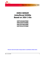
Pin Configurations
Pin Configurations (×8 configuration)
/xxx indicates active low signal.
Notes: 1. Not internally connected with die.
2. Don't connect. Internally connected.
3. Input only pins (address, command, CKE, ODT and /RESET) do not supply termination.
Pin name Function Pin name Function
A0 to A13*
3
Address inputs
A10(AP): Auto precharge
A12(/BC): Burst chop
/RESET*
3
Active low asynchronous reset
BA0 to BA2*
3
Bank select VDD Supply voltage for internal circuit
DQ0 to DQ7 Data input/output VSS Ground for internal circuit
DQS, /DQS Differential data strobe VDDQ Supply voltage for DQ circuit
TDQS, /TDQS Termination data strobe VSSQ Ground for DQ circuit
/CS*
3
Chip select VREFDQ Reference voltage for DQ
/RAS, /CAS, /WE*
3
Command input VREFCA Reference voltage for CA
CKE*
3
Clock enable ZQ Reference pin for ZQ calibration
CK, /CK Differential clock input NC*
1
No connection
DM Write data mask NU*
2
Not usable
ODT*
3
ODT control
VSS VDD
1
VDDQ
VSS
VSS
2
VSSQ DQ0VSS
DQ2
DQ6VSSQ
VDDQ
VREFDQ
VSS
VDD
/CS
BA0
A7
/RESET
NC
NC
VDD
3
NC
DQS
/DQS
DQ4
/RAS
/CAS
/WE
BA2
A9
A13
7
NU/(/TDQS)
DM/TDQS
DQ1
VDD
DQ7
CK
/CK
A10(AP)
NC
A11
NC
8
VSS
VSSQ VDDQ
VSSQ
DQ3
VSS
DQ5
VSS
VDD
ZQ
VREFCA
A6
A8
CKE
VSS
VSS
9
VDD
VSSQ
VDDQ
NC
VDD
(Top view)
78-ball FBGA
ODT
NC
A
B
C
D
E
F
G
H
J
A3
VDD A0 A12(/BC) BA1 VDD
A5VSS A2 A1 A4 VSS
K
L
M
N

EDJ1108EJBG, EDJ1116EJBG
Preliminary Data Sheet E1949E11 (Ver. 1.1)
4
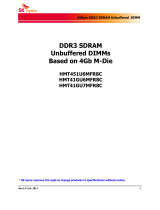
Pin Configurations (× 16 configuration)
/xxx indicates active low signal.
Notes: 1. Not internally connected with die.
2. Input only pins (address, command, CKE, ODT and /RESET) do not supply termination.
Pin name Function Pin name Function
A0 to A12*
2
Address inputs
A10(AP): Auto precharge
A12(/BC): Burst chop
/RESET*
2
Active low asynchronous reset
BA0 to BA2*
2
Bank select VDD Supply voltage for internal circuit
DQU0 to DQU7
DQL0 to DQL7
Data input/output VSS Ground for internal circuit
DQSU, /DQSU
DQSL, /DQSL
Differential data strobe VDDQ Supply voltage for DQ circuit
/CS*
2
Chip select VSSQ Ground for DQ circuit
/RAS, /CAS, /WE*
2
Command input VREFDQ Reference voltage for DQ
CKE*
2
Clock enable VREFCA Reference voltage for CA
CK, /CK Differential clock input ZQ Reference pin for ZQ calibration
DMU, DML Write data mask NC*
1
No connection
ODT*
2
ODT control
A
B
C
D
E
F
G
H
J
K
L
VDDQ
1
VDDQ
VSS
NC
2
VDD VSSVSSQ
DQU3
VDDQVSSQ
VSSQ
VSS
3
DQU7DQU5
DQU1
DMU
DQL0
VDD /CAS
/RAS
7
DQU4
/DQSU
DQSU
DQU0
DML
/CK
8
VDDQ
DQU6 VSSQ
DQU2
VSSQ VDD
VSSQ
VDD
M
N
P
T
VSS /RESET NC NC
NC
A8
9
VSS
VDDQ
VDDQ DQL2
DQL6VSSQ
VDDQ
VREFDQ
DQSL
/DQSL
DQL4
DQL1
VDD
DQL3
VSS VSSQ
DQL7 DQL5 VDDQ
VSSQ
VDDQ
CK VSS NC
VDD
BA0
A3
A5
BA2
A0
A2
A12(/BC)
A1
VREFCA
BA1
A4
VSS
VSS
(Top view)
96-ball FBGA
/CS /WE
ODT
VSS
VSS
R
A7 A9 A11 A6 VDDVDD
A10(AP)
VSS
VDD
NCZQNC
CKE

EDJ1108EJBG, EDJ1116EJBG
Preliminary Data Sheet E1949E11 (Ver. 1.1)
5
CONTENTS
Specifications ........................................................................................................................................ 1
Features ................................................................................................................................................ 1
Ordering Information ............................................................................................................................. 2
Part Number .......................................................................................................................................... 2
Operating Frequency ............................................................................................................................ 2
Detailed Information .............................................................................................................................. 2
Pin Configurations ................................................................................................................................. 3
1. Electrical Conditions ...................................................................................................................... 6
1.1 Absolute Maximum Ratings ..............................................................................................................6
1.2 Operating Temperature Condition ....................................................................................................6
1.3 Recommended DC Operating Conditions ........................................................................................7
1.4 IDD and IDDQ Measurement Conditions ..........................................................................................8
2. Electrical Specifications ............................................................................................................... 19
2.1 DC Characteristics ..........................................................................................................................19
2.2 Pin Capacitance ..............................................................................................................................21
2.3 Standard Speed Bins ......................................................................................................................23
3. Package Drawing ......................................................................................................................... 28
3.1 78-ball FBGA ..................................................................................................................................28
3.2 96-ball FBGA ..................................................................................................................................29
4. Recommended Soldering Conditions .......................................................................................... 30

EDJ1108EJBG, EDJ1116EJBG
Preliminary Data Sheet E1949E11 (Ver. 1.1)
6
1. Electrical Conditions
• All voltages are referenced to VSS (GND)
• Execute power-up and Initialization sequence before proper device operation is achieved.
1.1 Absolute Maximum Ratings
Notes: 1. Stresses greater than those listed under Absolute Maximum Ratings may cause permanent damage to the device. This
is a stress rating only and functional operation of the device at these or any other conditions above those indicated in the
operational sections of this specification is not implied. Exposure to absolute maximum rating conditions for extended
periods may affect reliability.
2. Storage temperature is the case surface temperature on the center/top side of the DRAM.
3. VDD and VDDQ must be within 300mV of each other at all times; and VREF must be no greater than 0.6 × VDDQ, When
VDD and VDDQ are less than 500mV; VREF may be equal to or less than 300mV.
Caution: Exposing the device to stress above those listed in Absolute Maximum Ratings could cause
permanent damage. The device is not meant to be operated under conditions outside the limits
described in the operational section of this specification. Exposure to Absolute Maximum Rating
conditions for extended periods may affect device reliability.
1.2 Operating Temperature Condition
Notes: 1. Operating temperature is the case surface temperature on the center/top side of the DRAM.
2. The Normal Temperature Range specifies the temperatures where all DRAM specifications will be supported. During
operation, the DRAM case temperature must be maintained between 0°C to +85°C under all operating conditions.
3. Some applications require operation of the DRAM in the Extended Temperature Range between +85°C and +95°C case
temperature. Full specifications are guaranteed in this range, but the following additional conditions apply:
a) Refresh commands must be doubled in frequency, therefore reducing the refresh interval tREFI to 3.9µs. (This double
refresh requirement may not apply for some devices.)
b) If Self-refresh operation is required in the Extended Temperature Range, then it is mandatory to either use the Manual
Self-Refresh mode with Extended Temperature Range capability (MR2 bit [A6, A7] = [0, 1]) or enable the optional Auto
Self-Refresh mode (MR2 bit [A6, A7] = [1, 0]).
Table 1: Absolute Maximum Ratings
Parameter Symbol Rating Unit Notes
Power supply voltage VDD −0.4 to +1.975 V 1, 3
Power supply voltage for output VDDQ −0.4 to +1.975 V 1, 3
Input voltage VIN −0.4 to +1.975 V 1
Output voltage VOUT −0.4 to +1.975 V 1
Reference voltage VREFCA −0.4 to 0.6 × VDD V 3
Reference voltage for DQ VREFDQ −0.4 to 0.6 × VDDQ V 3
Storage temperature Tstg −55 to +100 °C1, 2
Power dissipation PD 1.0 W 1
Short circuit output current IOUT 50 mA 1
Table 2: Operating Temperature Condition
Parameter Symbol Rating Unit Notes
Operating case temperature TC 0 to +95 °C 1, 2, 3

EDJ1108EJBG, EDJ1116EJBG
Preliminary Data Sheet E1949E11 (Ver. 1.1)
7
1.3 Recommended DC Operating Conditions
Notes: 1. Maximum DC value may not be greater than 1.425V. The DC value is the linear average of VDD/VDDQ(t) over a very
long period of time (e.g. 1 sec).
2. If maximum limit is exceeded, input levels shall be governed by DDR3 specifications.
3. Under these supply voltages, the device operates to this DDR3L specifcation.
4. Once initialized for DDR3L operation, DDR3 operation may only be used if the device is in reset while
5. VDD and VDDQ are changed for DDR3 operation shown as following timing wave form.
Notes: 1. If minimum limit is exceeded, input levels shall be governed by DDR3L specifications.
2. Under 1.5V operation, this DDR3L device operates to the DDR3 specifcations under the same speedtimings as defined
for this device.
3. Once initialized for DDR3 operation, DDR3L operation may only be used if the device is in reset while VDD and VDDQ
are changed for DDR3L operation shown as below.
Table 3: Recommended DC Operating Conditions (TC = 0°C to +85°C), DDR3L Operation
Parameter Symbol min. typ. max. Unit Notes
Supply voltage VDD 1.283 1.35 1.45 V 1, 2, 3, 4
Supply voltage for DQ VDDQ 1.283 1.35 1.45 V 1, 2, 3, 4
Table 4: Recommended DC Operating Conditions (TC = 0°C to +85°C), DDR3 Operation
Parameter Symbol min typ max Unit Notes
Supply voltage VDD 1.425 1.5 1.575 V 1, 2, 3
Supply voltage for DQ VDDQ 1.425 1.5 1.575 V 1, 2, 3
Figure 1: VDD/VDDQ Voltage Switch between DDR3L and DDR3
T(min) = 10ns
T(min) = 200µs
T(min) = 10ns
T = 500µs
tIS
Note: 1. From time point Td until Tk, NOP or DES commands must be applied between MRS and ZQCL commands.
: VIH or VIL
CK, /CK
VDD, VDDQ (DDR3)
VDD, VDDQ (DDR3L)
/RESET
CKE
Command
BA
ODT
RTT
tXPR tMRD tMRD tMRD tMOD
tCKSRX
tIS
tIS tIS
Ta Tb Tc Td Te Tf Tg Th Ti Tj Tk
T(min) = 10ns
tDLLK
tZQinit
*1 *1
Valid
Valid
Valid
Valid
MRS
Static low in case RTT_Nore is enabled at time Tg, otherwise static high or low
MRS MRS MRS
ZQCL
MR2 MR3 MR1 MR0

EDJ1108EJBG, EDJ1116EJBG
Preliminary Data Sheet E1949E11 (Ver. 1.1)
8
1.4 IDD and IDDQ Measurement Conditions
In this chapter, IDD and IDDQ measurement conditions such as test load and patterns are defined.
The figure Measurement Setup and Test Load for IDD and IDDQ Measurements shows the setup and test load for IDD
and IDDQ measurements.
• IDD currents (such as IDD0, IDD1, IDD2N, IDD2NT, IDD2P0, IDD2P1, IDD2Q, IDD3N, IDD3P, IDD4R, IDD4W,
IDD5B, IDD6, IDD6ET, IDD6TC and IDD7) are measured as time-averaged currents with all VDD balls of the DDR3
SDRAM under test tied together. Any IDDQ current is not included in IDD currents.
• IDDQ currents (such as IDDQ2NT and IDDQ4R) are measured as time-averaged currents with all VDDQ balls of
the DDR3 SDRAM under test tied together. Any IDD current is not included in IDDQ currents.
Note:IDDQ values cannot be directly used to calculate I/O power of the DDR3 SDRAM. They can be used to support
correlation of simulated I/O power to actual I/O power as outlined in correlation from simulated channel I/O
power to actual channel I/O power supported by IDDQ measurement.
For IDD and IDDQ measurements, the following definitions apply:
• L and 0: VIN ≤ VIL(AC)max
• H and 1: VIN ≥ VIH(AC)min
• MID-LEVEL: defined as inputs are VREF = VDDQ / 2
• FLOATING: don't care or floating around VREF.
• Timings used for IDD and IDDQ measurement-loop patterns are provided in Timings used for IDD and IDDQ
Measurement-Loop Patterns table.
• Basic IDD and IDDQ measurement conditions are described in Basic IDD and IDDQ Measurement Conditions
table.
Note:The IDD and IDDQ measurement-loop patterns need to be executed at least one time before actual IDD or
IDDQ measurement is started.
• Detailed IDD and IDDQ measurement-loop patterns are described in IDD0 Measurement-Loop Pattern table
through IDD7 Measurement-Loop Pattern table.
• IDD Measurements are done after properly initializing the DDR3 SDRAM. This includes but is not limited to setting.
RON = RZQ/7 (34Ω in MR1);
Qoff = 0B (Output Buffer enabled in MR1);
RTT_Nom = RZQ/6 (40Ω in MR1);
RTT_WR = RZQ/2 (120Ω in MR2);
TDQS Feature disabled in MR1
• Define D = {/CS, /RAS, /CAS, /WE} : = {H, L, L, L}
• Define /D = {/CS, /RAS, /CAS, /WE} : = {H, H, H, H}

EDJ1108EJBG, EDJ1116EJBG
Preliminary Data Sheet E1949E11 (Ver. 1.1)
9
Figure 2: Measurement Setup and Test Load for IDD and IDDQ Measurements
Figure 3: Correlation from Simulated Channel I/O Power to Actual Channel I/O Power
Supported by IDDQ Measurement
IDD
IDDQ
VDDQ/2
DDR3
SDRAM
VDD
VDDQ
VSS
VSSQ
CKE
/CS
/RAS, /CAS, /WE
Address, BA
ODT
ZQ
RTT = 25Ω
/RESET
CK, /CK
DQS, /DQS,
DQ, DM,
TDQS, /TDQS
Application specific
memory channel
environment
Channel
I/O power
simulation
Channel I/O power
number
Correction
Correlation
IDDQ
measurement
IDDQ
simulation
IDDQ
Test load

EDJ1108EJBG, EDJ1116EJBG
Preliminary Data Sheet E1949E11 (Ver. 1.1)
10
1.4.1 Timings Used for IDD and IDDQ Measurement-Loop Patterns
Table 5: Timings Used for IDD and IDDQ Measurement-Loop Patterns
DDR3-800 DDR3-1066 DDR3-1333 DDR3-1600
Parameter 6-6-6 7-7-7 9-9-9 11-11-11 Unit
CL 67911nCK
tCK(min) 2.5 1.875 1.5 1.25 ns
nRCD(min) 67911nCK
nRC(min) 21 27 33 39 nCK
nRAS(min) 15 20 24 28 nCK
nRP(min)67911nCK
nFAW (1KB) 16 20 20 24 nCK
nFAW (2KB, 4KB) 20 27 30 32 nCK
nRRD (1KB) 4445nCK
nRRD (2KB, 4KB) 4656nCK
nRFC (1Gb)44597488nCK
nRFC (2Gb) 64 86 107 128 nCK
nRFC (4Gb) 104 139 174 208 nCK
DDR3-1866
Parameter 13-13-13 Unit
CL 13 nCK
tCK(min) 1.07 ns
nRCD(min) 13 nCK
nRC(min) 45 nCK
nRAS(min) 32 nCK
nRP(min) 13 nCK
nFAW (1KB) 26 nCK
nFAW (2KB, 4KB) 33 nCK
nRRD (1KB) 5 nCK
nRRD (2KB, 4KB) 6 nCK
nRFC (1Gb) 103 nCK
nRFC (2Gb) 150 nCK
nRFC (4Gb) 243 nCK

EDJ1108EJBG, EDJ1116EJBG
Preliminary Data Sheet E1949E11 (Ver. 1.1)
11
1.4.2 Basic IDD and IDDQ Measurement Conditions
Table 6: Basic IDD and IDDQ Measurement Conditions
Parameter Symbol Description
Operating one bank
active precharge
current
IDD0
CKE: H; External clock: on; tCK, nRC, nRAS, CL: see Table 5; BL: 8*
1
; AL: 0; /CS: H
between ACT and PRE; Command, address, bank address inputs: partially toggling
according to Table 7; Data I/O: MID-LEVEL; DM: stable at 0;
Bank activity: cycling with one bank active at a time: 0,0,1,1,2,2,... (see Table 7);
Output buffer and RTT: enabled in MR*
2
; ODT signal: stable at 0; Pattern details: see
Table 7
Operating one bank
active-read-precharge
current
IDD1
CKE: H; External clock: On; tCK, nRC, nRAS, nRCD, CL: see Table 5; BL: 8*
1,
*
6
; AL:
0; /CS: H between ACT, RD and PRE; Command, address, bank address inputs, data
I/O: partially toggling according to Table 8;
DM: stable at 0; Bank activity: cycling with one bank active at a time: 0,0,1,1,2,2,...
(see Table 8); Output buffer and RTT: enabled in MR*
2
; ODT Signal: stable at 0;
Pattern details: see Table 8
Precharge standby
current
IDD2N
CKE: H; External clock: on; tCK, CL: see Table 5 BL: 8*
1
; AL: 0; /CS: stable at 1;
Command, address, bank address Inputs: partially toggling according to Table 9;
data I/O: MID-LEVEL; DM: stable at 0; bank activity: all banks closed; output buffer
and RTT: enabled in mode registers*
2
; ODT signal: stable at 0; pattern details: see
Table 9
Precharge standby
ODT current
IDD2NT
CKE: H; External clock: on; tCK, CL: see Table 5; BL: 8*
1
; AL: 0; /CS: stable at 1;
Command, address, bank address Inputs: partially toggling according to Table 10;
data I/O: MID-LEVEL; DM: stable at 0; bank activity: all banks closed; output buffer
and RTT: enabled in MR*
2
; ODT signal: toggling according to Table 10; pattern
details: see Table 10
Precharge standby
ODT IDDQ current
IDDQ2NT
Same definition like for IDD2NT, however measuring IDDQ current instead of IDD
current
Precharge power-down
current slow exit
IDD2P0
CKE: L; External clock: on; tCK, CL: see Table 5; BL: 8*
1
; AL: 0; /CS: stable at 1;
Command, address, bank address inputs: stable at 0; data I/O: MID-LEVEL; DM:
stable at 0; bank activity: all banks closed; output buffer and RTT: EMR*
2
; ODT
signal: stable at 0; precharge power down mode: slow exit*
3
Precharge power-down
current fast exit
IDD2P1
CKE: L; External clock: on; tCK, CL: see Table 6; BL: 8*
1
; AL: 0; /CS: stable at 1;
Command, address, bank address Inputs: stable at 0; data I/O: MID-LEVEL;
DM:stable at 0; bank activity: all banks closed; output buffer and RTT: enabled in
MR*
2
; ODT signal: stable at 0; precharge power down mode: fast exit*
3
Precharge quiet
standby current
IDD2Q
CKE: H; External clock: On; tCK, CL: see Table 5; BL: 8*
1
; AL: 0; /CS: stable at 1;
Command, address, bank address Inputs: stable at 0; data I/O: MID-LEVEL;
DM: stable at 0;bank activity: all banks closed; output buffer and RTT: enabled in
MR*
2
; ODT signal: stable at 0
Active standby current IDD3N
CKE: H; External clock: on; tCK, CL: see Table 5; BL: 8*
1
; AL: 0; /CS: stable at 1;
Command, address, bank address Inputs: partially toggling according to Table 9;
data I/O: MID-LEVEL; DM: stable at 0;
bank activity: all banks open; output buffer and RTT: enabled in MR*
2
;
ODT signal: stable at 0; pattern details: see Table 9
Active power-down
current
IDD3P
CKE: L; External clock: on; tCK, CL: see Table 5; BL: 8*
1
; AL: 0; /CS: stable at 1;
Command, address, bank address inputs: stable at 0; data I/O: MID-LEVEL;
DM:stable at 0; bank activity: all banks open; output buffer and RTT:
enabled in MR*
2
; ODT signal: stable at 0
Operating burst read
current
IDD4R
CKE: H; External clock: on; tCK, CL: see Table 5; BL: 8*
1,
*
6
; AL: 0; /CS: H between
RD; Command, address, bank address Inputs: partially toggling according to
Table 11; data I/O: seamless read
data burst with different data between one burst and the next one according to
Table 11; DM: stable at 0;
bank activity: all banks open, RD commands cycling through banks: 0,0,1,1,2,2,...
(see Table 11); Output buffer and RTT: enabled in MR*
2
; ODT signal: stable at 0;
pattern details: see Table 11
Operating burst read
IDDQ current
IDDQ4R
Same definition like for IDD4R, however measuring IDDQ current instead of IDD
current

EDJ1108EJBG, EDJ1116EJBG
Preliminary Data Sheet E1949E11 (Ver. 1.1)
12
Notes: 1. Burst Length: BL8 fixed by MRS: MR0 bits [1,0] = [0,0].
2. MR: Mode Register
Output buffer enable: set MR1 bit A12 = 1 and MR1 bits [5, 1] = [0,1];
RTT_Nom enable: set MR1 bits [9, 6, 2] = [0, 1, 1]; RTT_WR enable: set MR2 bits [10, 9] = [1,0].
3. Precharge power down mode: set MR0 bit A12= 0 for Slow Exit or MR0 bit A12 = 1 for fast exit.
4. Auto self-refresh (ASR): set MR2 bit A6 = 0 to disable or 1 to enable feature.
5. Self-refresh temperature range (SRT): set MR0 bit A7= 0 for normal or 1 for extended temperature range.
6. Read burst type: nibble sequential, set MR0 bit A3 = 0
Operating burst write current IDD4W
CKE: H; External clock: on; tCK, CL: see Table 5; BL: 8*
1
; AL: 0; /CS: H between WR;
command, address, bank address inputs: partially toggling according to Table 12;
data I/O: seamless write data burst with different data between one burst and the next
one according to IDD4W Measurement-Loop Pattern table; DM: stable at 0; bank
activity: all banks open,
WR commands cycling through banks: 0,0,1,1,2,2,.. (see Table 12); Output buffer
and RTT: enabled in MR*
2
; ODT signal: stable
at H; pattern details: see Table 12
Burst refresh current IDD5B
CKE: H; External clock: on; tCK, CL, nRFC: see Table 5; BL: 8*
1
; AL: 0; /CS: H
between REF;
Command, address, bank address Inputs: partially toggling according to Table 13;
data I/O: MID-LEVEL; DM: stable at 0;
bank activity: REF command every nRFC (Table 13); output buffer and RTT: enabled
in MR*
2
; ODT signal: stable at 0; pattern
details: see Table 13
Self-refresh current: normal
temperature range
IDD6
TC: 0 to 85°C; ASR: disabled*
4
; SRT:
Normal*
5
; CKE: L; External clock: off; CK and /CK: L; CL: see Table 5; BL: 8*
1
;
AL: 0; /CS, command, address, bank address, data I/O: MID-LEVEL; DM: stable
at 0; bank activity: Self-refresh operation; output buffer and RTT: enabled in MR*
2
;
ODT signal: MID-LEVEL
Self-refresh current: extended
temperature range
IDD6ET
TC: 0 to 95°C; ASR: Disabled*
4
; SRT: Extended*
5
; CKE: L; External clock: off; CK
and /CK: L; CL: Table 5; BL: 8*
1
; AL: 0; /CS, command, address, bank address, data
I/O: MID-LEVEL;
DM: stable at 0; bank activity: Extended temperature self-refresh operation; output
buffer and RTT: enabled in MR*
2
; ODT signal: MID-LEVEL
Auto self-refresh current
(Optional)
IDD6TC
TC: 0 to 95°C; ASR: Enabled*
4
; SRT: Normal*
5
; CKE: L; External clock: off;
CK and /CK: L; CL: Table 5; BL: 8*
1
; AL: 0; /CS, command, address, bank address,
data I/O: MID-LEVEL; DM: stable at 0; bank activity: Auto self-refresh operation;
output buffer and RTT: enabled in MR*
2
; ODT signal: MID-LEVEL
Operating bank interleave
read current
IDD7
CKE: H; External clock: on; tCK, nRC, nRAS, nRCD, nRRD, nFAW, CL: see Table 5;
BL: 8*
1,
*
6
; AL: CL-1; /CS: H between ACT and RDA; Command, address, bank
address Inputs: partially toggling according to Table 14; data I/O: read data bursts
with different data between one burst and the next one according to Table 14; DM:
stable at 0; bank activity: two times interleaved cycling through banks (0, 1, …7) with
different addressing, see Table 14; output buffer and RTT: enabled in MR*
2
; ODT
signal: stable at 0; pattern details: see Table 14
RESET low current IDD8
/RESET: low; External clock: off; CK and /CK: low; CKE: FLOATING; /CS, command,
address, bank address, Data IO: FLOATING; ODT signal: FLOATING
RESET low current reading is valid once power is stable and /RESET has been low
for at least 1ms.
Table 6: Basic IDD and IDDQ Measurement Conditions (cont’d)
Parameter Symbol Description

EDJ1108EJBG, EDJ1116EJBG
Preliminary Data Sheet E1949E11 (Ver. 1.1)
13
Notes: 1. DM must be driven low all the time. DQS, /DQS are MID-LEVEL.
2. DQ signals are MID-LEVEL.
3. BA: BA0 to BA2.
4. Am: m means Most Significant Bit (MSB) of Row address.
Table 7: IDD0 Measurement-Loop Pattern
CK,
/CK CKE
Sub
-Loop
Cycle
number
Com-
mand /CS /RAS /CAS /WE ODT BA*
3
A11
-Am A10
A7
-A9
A3
-A6
A0
-A2 Data*
2
Toggling Static H
0
0 ACT00110000000
1, 2 D, D10000000000
3, 4 /D, /D11110000000
… Repeat pattern 1…4 until nRAS − 1, truncate if necessary
nRASPRE00100000000
… Repeat pattern 1...4 until nRC − 1, truncate if necessary
1 × nRC
+ 0
ACT001100000F0
1 × nRC
+1, 2
D, D100000000F0
1 × nRC
+ 3, 4
/D, /D111100000F0
… Repeat pattern nRC + 1,...,4 until 1 × nRC + nRAS − 1, truncate if necessary
1 × nRC
+ nRAS
PRE001000000F0
… Repeat nRC + 1,...,4 until 2 × nRC − 1, truncate if necessary
12 × nRC Repeat Sub-Loop 0, use BA= 1 instead
24 × nRC Repeat Sub-Loop 0, use BA= 2 instead
36 × nRC Repeat Sub-Loop 0, use BA= 3 instead
48 × nRC Repeat Sub-Loop 0, use BA= 4 instead
5 10 × nRC Repeat Sub-Loop 0, use BA= 5 instead
6 12 × nRC Repeat Sub-Loop 0, use BA= 6 instead
7 14 × nRC Repeat Sub-Loop 0, use BA= 7 instead

EDJ1108EJBG, EDJ1116EJBG
Preliminary Data Sheet E1949E11 (Ver. 1.1)
14
Notes: 1. DM must be driven low all the time. DQS, /DQS are used according to read commands, otherwise MID-LEVEL.
2. Burst sequence driven on each DQ signal by read command. Outside burst operation, DQ signals are MID-LEVEL.
3. BA: BA0 to BA2.
4. Am: m means Most Significant Bit (MSB) of Row address.
Table 8: IDD1 Measurement-Loop Pattern
CK,
/CK CKE
Sub
-Loop
Cycle
number
Com-
mand /CS /RAS /CAS /WE ODT BA*
3
A11
-Am A10
A7
-A9
A3
-A6
A0
-A2 Data*
2
Toggling Static H
0
0 ACT00110000000⎯
1, 2 D, D10000000000⎯
3, 4 /D, /D11110000000⎯
… Repeat pattern 1...4 until nRCD − 1, truncate if necessary
nRCDRD0101000000000000000
… Repeat pattern 1...4 until nRAS − 1, truncate if necessary
nRASPRE00100000000⎯
… Repeat pattern 1...4 until nRC − 1, truncate if necessary
1 × nRC
+ 0
ACT001100000F0⎯
1 × nRC
+ 1, 2
D, D100000000F0⎯
1 × nRC
+ 3, 4
/D, /D111100000F0⎯
… Repeat pattern nRC + 1,..., 4 until nRC + nRCD − 1, truncate if necessary
1 × nRC
+ nRCD
RD010100000F000110011
… Repeat pattern nRC + 1,..., 4 until nRC +nRAS − 1, truncate if necessary
1 × nRC
+ nRAS
PRE001000000F0⎯
… Repeat pattern nRC + 1,..., 4 until 2 × nRC − 1, truncate if necessary
12 × nRC Repeat Sub-Loop 0, use BA= 1 instead
24 × nRC Repeat Sub-Loop 0, use BA= 2 instead
36 × nRC Repeat Sub-Loop 0, use BA= 3 instead
48 × nRC Repeat Sub-Loop 0, use BA= 4 instead
5 10 × nRC Repeat Sub-Loop 0, use BA= 5 instead
6 12 × nRC Repeat Sub-Loop 0, use BA= 6 instead
7 14 × nRC Repeat Sub-Loop 0, use BA= 7 instead

EDJ1108EJBG, EDJ1116EJBG
Preliminary Data Sheet E1949E11 (Ver. 1.1)
15
Notes: 1. DM must be driven low all the time. DQS, /DQS are MID-LEVEL.
2. DQ signals are MID-LEVEL.
3. BA: BA0 to BA2.
4. Am: m means Most Significant Bit (MSB) of Row address.
Notes: 1. DM must be driven low all the time. DQS, /DQS are MID-LEVEL.
2. DQ signals are MID-LEVEL.
3. BA: BA0 to BA2.
4. Am: m means Most Significant Bit (MSB) of Row address.
Table 9: IDD2N and IDD3N Measurement-Loop Pattern
CK,
/CK CKE
Sub
-Loop
Cycle
number
Com-
mand /CS /RAS /CAS /WE ODT BA*
3
A11
-Am A10
A7
-A9
A3
-A6
A0
-A2 Data*
2
Toggling Static H
0
0 D 10000000000
1 D 10000000000
2 /D111100000F0
3 /D111100000F0
1 4 to 7 Repeat Sub-Loop 0, use BA= 1 instead
2 8 to 11 Repeat Sub-Loop 0, use BA= 2 instead
3 12 to 15 Repeat Sub-Loop 0, use BA= 3 instead
4 16 to 19 Repeat Sub-Loop 0, use BA= 4 instead
5 20 to 23 Repeat Sub-Loop 0, use BA= 5 instead
6 24 to 27 Repeat Sub-Loop 0, use BA= 6 instead
7 28 to 31 Repeat Sub-Loop 0, use BA= 7 instead
Table 10: IDD2NT and IDDQ2NT Measurement-Loop Pattern
CK,
/CK CKE
Sub
-Loop
Cycle
number
Com-
mand /CS /RAS /CAS /WE ODT BA*
3
A11
-Am A10
A7
-A9
A3
-A6
A0
-A2 Data*
2
Toggling Static H
0
0 D 10000000000
1 D 10000000000
2 /D111100000F0
3 /D111100000F0
1 4 to 7 Repeat Sub-Loop 0, but ODT = 0 and BA= 1
2 8 to 11 Repeat Sub-Loop 0, but ODT = 1 and BA= 2
3 12 to 15 Repeat Sub-Loop 0, but ODT = 1 and BA= 3
4 16 to 19 Repeat Sub-Loop 0, but ODT = 0 and BA= 4
5 20 to 23 Repeat Sub-Loop 0, but ODT = 0 and BA= 5
6 24 to 27 Repeat Sub-Loop 0, but ODT = 1 and BA= 6
7 28 to 31 Repeat Sub-Loop 0, but ODT = 1 and BA= 7

EDJ1108EJBG, EDJ1116EJBG
Preliminary Data Sheet E1949E11 (Ver. 1.1)
16
Notes: 1. DM must be driven low all the time. DQS, /DQS are used according to read commands, otherwise MID-LEVEL.
2. Burst sequence driven on each DQ signal by read command. Outside burst operation, DQ signals are MID-LEVEL.
3. BA: BA0 to BA2.
4. Am: m means Most Significant Bit (MSB) of Row address.
Table 11: IDD4R and IDDQ4R Measurement-Loop Pattern
CK,
/CK CKE
Sub
-Loop
Cycle
number
Com-
mand /CS /RAS /CAS /WE ODT BA*
3
A11
-Am A10
A7
-A9
A3
-A6
A0
-A2 Data*
2
Toggling Static H
0
0 RD0101000000000000000
1 D 10000000000⎯
2,3 /D, /D11110000000⎯
4 RD010100000F000110011
5 D 100000000F0⎯
6,7 /D, /D111100000F0⎯
1 8 to 15 Repeat Sub-Loop 0, but BA= 1
2 16 to 23 Repeat Sub-Loop 0, but BA= 2
3 24 to 31 Repeat Sub-Loop 0, but BA= 3
4 32 to 39 Repeat Sub-Loop 0, but BA= 4
5 40 to 47 Repeat Sub-Loop 0, but BA= 5
6 48 to 55 Repeat Sub-Loop 0, but BA= 6
7 56 to 63 Repeat Sub-Loop 0, but BA= 7

EDJ1108EJBG, EDJ1116EJBG
Preliminary Data Sheet E1949E11 (Ver. 1.1)
17
Notes: 1. DM must be driven low all the time. DQS, /DQS are used according to write commands, otherwise MID-LEVEL.
2. Burst sequence driven on each DQ signal by write command. Outside burst operation, DQ signals are MID-LEVEL.
3. BA: BA0 to BA2.
4. Am: m means Most Significant Bit (MSB) of Row address.
Notes: 1. DM must be driven low all the time. DQS, /DQS are MID-LEVEL.
2. DQ signals are MID-LEVEL.
3. BA: BA0 to BA2.
4. Am: m means Most Significant Bit (MSB) of Row address.
Table 12: IDD4W Measurement-Loop Pattern
CK,
/CK CKE
Sub
-Loop
Cycle
number
Com-
mand /CS /RAS /CAS /WE ODT BA*
3
A11
-Am A10
A7
-A9
A3
-A6
A0
-A2 Data*
2
Toggling Static H
0
0 WR0100100000000000000
1 D 10001000000⎯
2,3 /D, /D11111000000⎯
4 WR010010000F000110011
5 D 100010000F0⎯
6,7 /D, /D111110000F0⎯
1 8 to 15 Repeat Sub-Loop 0, but BA= 1
2 16 to 23 Repeat Sub-Loop 0, but BA= 2
3 24 to 31 Repeat Sub-Loop 0, but BA= 3
4 32 to 39 Repeat Sub-Loop 0, but BA= 4
5 40 to 47 Repeat Sub-Loop 0, but BA= 5
6 48 to 55 Repeat Sub-Loop 0, but BA= 6
7 56 to 63 Repeat Sub-Loop 0, but BA= 7
Table 13: IDD5B Measurement-Loop Pattern
CK,
/CK CKE
Sub
-Loop
Cycle
number
Com-
mand /CS /RAS /CAS /WE ODT BA*
3
A11
-Am A10
A7
-A9
A3
-A6
A0
-A2 Data*
2
Toggling Static H
0
0 REF00010000000⎯
1, 2 D 10000000000⎯
3,4 /D, /D111100000F0⎯
1
5 to 8 Repeat cycles 1...4, but BA= 1
9 to 12 Repeat cycles 1...4, but BA= 2
13 to 16 Repeat cycles 1...4, but BA= 3
17 to 20 Repeat cycles 1...4, but BA= 4
21 to 24 Repeat cycles 1...4, but BA= 5
25 to 28 Repeat cycles 1...4, but BA= 6
29 to 32 Repeat cycles 1...4, but BA= 7
2
33 to
nRFC − 1
Repeat Sub-Loop 1, until nRFC − 1. Truncate, if necessary.

EDJ1108EJBG, EDJ1116EJBG
Preliminary Data Sheet E1949E11 (Ver. 1.1)
18
Notes: 1. DM must be driven low all the time. DQS, /DQS are used according to read commands, otherwise MID-LEVEL.
2. Burst sequence driven on each DQ signal by read command. Outside burst operation, DQ signals are MID-LEVEL.
3. BA: BA0 to BA2.
4. Am: m means Most Significant Bit (MSB) of Row address.
Table 14: IDD7 Measurement-Loop Pattern
CK,
/CK CKE
Sub
-Loop
Cycle
number
Com-
mand /CS /RAS /CAS /WE ODT BA*
3
A11
-Am A10
A7
-A9
A3
-A6
A0
-A2 Data*
2
Toggling Static H
0
0 ACT00110000000⎯
1 RDA 0 1 0 1 0 0 0 1 0 0 0 00000000
2 D 10000000000⎯
… Repeat above D Command until nRRD − 1
1
nRRD ACT 0 0 1 1 0 1 0 0 0 F 0 ⎯
nRRD + 1 RDA 0 1 0 1 0 1 0 1 0 F 0 00110011
nRRD + 2D 100001000F0⎯
… Repeat above D Command until 2 × nRRD − 1
22 × nRRD Repeat Sub-Loop 0, but BA= 2
33 × nRRD Repeat Sub-Loop 1, but BA= 3
44 × nRRD
D100003000F0⎯
Assert and repeat above D Command until nFAW − 1, if necessary
5 nFAW Repeat Sub-Loop 0, but BA= 4
6
nFAW
+ nRRD
Repeat Sub-Loop 1, but BA= 5
7
nFAW
+ 2 × nRRD
Repeat Sub-Loop 0, but BA= 6
8
nFAW
+ 3 × nRRD
Repeat Sub-Loop 1, but BA= 7
9
nFAW
+ 4 × nRRD
D100007000F0⎯
Assert and repeat above D Command until 2 × nFAW − 1, if necessary
10
2 × nFAW
+ 0
ACT 0 0 1 1 0 0 0 0 0 F 0 ⎯
2 × nFAW
+ 1
RDA 0 1 0 1 0 0 0 1 0 F 0 00110011
2 × nFAW
+ 2
D100000000F0⎯
Repeat above D Command until 2 × nFAW + nRRD − 1
11
2 × nFAW
+ nRRD
ACT 0 0 1 1 0 1 0 0 0 0 0 ⎯
2 × nFAW
+ nRRD + 1
RDA 0 1 0 1 0 1 0 1 0 0 0 00000000
2 × nFAW
+ nRRD + 2
D10000100000⎯
Repeat above D Command until 2 × nFAW + 2 × nRRD − 1
12
2 × nFAW
+2 × nRRD
Repeat Sub-Loop 10, but BA= 2
13
2 × nFAW
+ 3 × nRRD
Repeat Sub-Loop 11, but BA= 3
14
2 × nFAW
+ 4 × nRRD
D10000300000⎯
Assert and repeat above D Command until 3 × nFAW − 1, if necessary
15 3 × nFAW Repeat Sub-Loop 10, but BA= 4
16
3 × nFAW
+nRRD
Repeat Sub-Loop 11, but BA= 5
17
3 × nFAW
+ 2 × nRRD
Repeat Sub-Loop 10, but BA= 6
18
3 × nFAW
+ 3 × nRRD
Repeat Sub-Loop 11, but BA= 7
19
3 × nFAW
+ 4 × nRRD
D10000700000⎯
Assert and repeat above D Command until 4 × nFAW − 1, if necessary

EDJ1108EJBG, EDJ1116EJBG
Preliminary Data Sheet E1949E11 (Ver. 1.1)
19
2. Electrical Specifications
2.1 DC Characteristics
Table 15: DC Characteristics 1 (TC = 0°C to +85°C, VDD, VDDQ = 1.283V to 1.45V)
Data rate × 8 × 16
Parameter Symbol (Mbps) max max Unit Notes
Operating current
(ACT-PRE)
IDD0
1333
1600
1866
48
52
TBD
55
60
TBD
mA
Operating current
(ACT-RD-PRE)
IDD1
1333
1600
1866
60
65
TBD
70
75
TBD
mA
Precharge power-down
standby current
IDD2P1
1333
1600
1866
20
20
TBD
20
20
TBD
mA Fast PD Exit
IDD2P0
1333
1600
1866
10
10
TBD
10
10
TBD
mA Slow PD Exit
Precharge standby current IDD2N
1333
1600
1866
30
30
TBD
30
30
TBD
mA
Precharge standby
ODT current
IDD2NT
1333
1600
1866
30
32
TBD
30
32
TBD
mA
Precharge quiet standby
current
IDD2Q
1333
1600
1866
30
30
TBD
30
30
TBD
mA
Active power-down current
(Always fast exit)
IDD3P
1333
1600
1866
25
25
TBD
25
26
TBD
mA
Active standby current IDD3N
1333
1600
1866
40
45
TBD
40
45
TBD
mA
Operating current
(Burst read operating)
IDD4R
1333
1600
1866
90
105
TBD
105
120
TBD
mA
Operating current
(Burst write operating)
IDD4W
1333
1600
1866
100
115
TBD
135
155
TBD
mA
Burst refresh current IDD5B
1333
1600
1866
135
140
TBD
135
140
TBD
mA
All bank interleave read
current
IDD7
1333
1600
1866
160
160
TBD
165
190
TBD
mA
RESET low current IDD8 10 10 mA

EDJ1108EJBG, EDJ1116EJBG
Preliminary Data Sheet E1949E11 (Ver. 1.1)
20
Table 16: Self-Refresh Current (TC = 0°C to +85°C, VDD, VDDQ = 1.283V to 1.45V)
Parameter Symbol max Unit Notes
Self-refresh current
normal temperature range
IDD6 10 mA
Self-refresh current
extended temperature range
IDD6ET 12 mA
Auto self-refresh current
(Optional)
IDD6TC ⎯ mA
/