Page is loading ...

Rev. 1.6 / Dec. 2010 1
2Gb DDR3 SDRAM
2Gb DDR3 SDRAM
Lead-Free&Halogen-Free
(RoHS Compliant)
H5TQ2G83BFR-xxC
H5TQ2G83BFR-xxI
H5TQ2G63BFR-xxC
H5TQ2G63BFR-xxI
* Hynix Semiconductor reserves the right to change products or specifications without notice.

Rev. 1.6 / Dec. 2010 2
Revision History
Revision No. History Draft Date Remark
0.1 Initial Release Dec. 2009
0.2 Added IDD Specification Feb. 2010
1.0 Add supported CL5 Jun. 2010
1.1 Modify the package outline with x16 Jun. 2010
1.2 Low power added Sep. 2010
1.3 M8 pin ball out update Sep. 2010
1.4 Added 1866 speed Suppport Nov. 2010
1.5 Added 2133 speed Suppport Dec. 2010
1.6 Added IDD Specification(2133 speed) Dec. 2010

Rev. 1.6 / Dec. 2010 3
Description
The H5TQ2G83BFR and H5TQ2G63BFR are a 2,147,483,648-bit CMOS Double Data Rate III (DDR3) Syn-
chronous DRAM, ideally suited for the main memory applications which requires large memory density and
high bandwidth. Hynix 2Gb DDR3 SDRAMs offer fully synchronous operations referenced to both rising and
falling edges of the clock. While all addresses and control inputs are latched on the rising edges of the CK
(falling edges of the CK), Data, Data strobes and Write data masks inputs are sampled on both rising and
falling edges of it. The data paths are internally pipelined and 8-bit prefetched to achieve very high band-
width.
Device Features and Ordering Information
FEATURES
* This product in compliance with the RoHS directive.
• VDD=VDDQ=1.5V +/- 0.075V
• Fully differential clock inputs (CK, CK
) operation
• Differential Data Strobe (DQS, DQS
)
• On chip DLL align DQ, DQS and DQS
transition with CK
transition
• DM masks write data-in at the both rising and falling
edges of the data strobe
• All addresses and control inputs except data,
data strobes and data masks latched on the
rising edges of the clock
• Programmable CAS latency 5, 6, 7, 8, 9, 10, 11, 12, 13
and 14 supported
• Programmable additive latency 0, CL-1, and CL-2
supported
• Programmable CAS Write latency (CWL) = 5, 6, 7, 8, 9,
10
• Programmable burst length 4/8 with both nibble
sequential and interleave mode
• BL switch on the fly
• 8banks
• Average Refresh Cycle (Tcase of 0
o
C~ 95
o
C)
- 7.8 µs at 0
o
C ~ 85
o
C
- 3.9 µs at 85
o
C ~ 95
o
C
Commercial Temperature (0
o
C~ 85
o
C)
Industrial Temperature ( -40
o
C~ 85
o
C)
• Auto Self Refresh supported
• JEDEC standard 82ball FBGA(x8), 96ball FBGA (x16)
• Driver strength selected by EMRS
• Dynamic On Die Termination supported
• Asynchronous RESET pin supported
• ZQ calibration supported
• TDQS (Termination Data Strobe) supported (x8 only)
• Write Levelization supported
• 8 bit pre-fetch

Rev. 1.6 / Dec. 2010 4
ORDERING INFORMATION
* xx means Speed Bin Grade
OPERATING FREQUENCY
* xx means Speed Bin Grade
Part No. Configuration Power Consumption Temperature Package
H5TQ2G83BFR-*xxC
256M x 8 Normal Consumption
Commercial
82ball FBGA
H5TQ2G83BFR-*xxI Industrial
H5TQ2G63BFR-*xxC
128M x 16 Normal Consumption
Commercial
96ball FBGA
H5TQ2G63BFR-*xxI Industrial
Speed
Grade
(Marking)
Frequency [MHz]
Remark
(CL-tRCD-tRP)
CL5 CL6 CL7 CL8 CL9 CL10 CL11 CL12 CL13 CL14
-G7 O O O O DDR3-1066 7-7-7
-H9 O O O O O O DDR3-1333 9-9-9
-PB O O O O O O O O O O DDR3-1600 11-11-11
-RD O O O O O O O DDR3-1866 13-13-13
-TE O O O O O O O DDR3-2133 14-14-14

Rev. 1.6 / Dec. 2010 5
Package Ballout/Mechanical Dimension
x8 Package Ball out (Top view): 82ball FBGA Package
1 2 3 4 5 6 7 8 9 10 11
A NC VSS VDD NC NF/TDQS VSS VDD NC A
B VSS VSSQ DQ0 DM/TDQS VSSQ VDDQ B
C VDDQ DQ2 DQS DQ1 DQ3 VSSQ C
D VSSQ DQ6 DQS VDD VSS VSSQ D
E VREFDQ VDDQ DQ4 DQ7 DQ5 VDDQ E
F NC VSS RAS CK VSS NC F
G ODT VDD CAS CK VDD CKE G
H NC CS WE A10/AP ZQ NC H
J VSS BA0 BA2 NC VREFCA VSS J
K VDD A3 A0 A12/BC BA1 VDD K
L VSS A5 A2 A1 A4 VSS L
M VDD A7 A9 A11 A6 VDD M
N NC VSS RESET A13 A14 A8 VSS NC N
1 2 3 4 5 6 7 8 9 10 11
12
A
B
C
D
E
F
G
H
J
K
L
M
N
Populated ball
Ball not populated
3
8910
(Top View: See the balls through the Package)
4
11

Rev. 1.6 / Dec. 2010 6
x16 Package Ball out (Top view): 96ball FBGA Package
1 2 3 4 5 6 7 8 9
A VDDQ DQU5 DQU7 DQU4 VDDQ VSS A
B VSSQ VDD VSS DQSU DQU6 VSSQ B
C VDDQ DQU3 DQU1 DQSU DQU2 VDDQ C
D VSSQ VDDQ DMU DQU0 VSSQ VDD D
E VSS VSSQ DQL0 DML VSSQ VDDQ E
F VDDQ DQL2 DQSL DQL1 DQL3 VSSQ F
G VSSQ DQL6 DQSL VDD VSS VSSQ G
H VREFDQ VDDQ DQL4 DQL7 DQL5 VDDQ H
J NC VSS RAS CK VSS NC J
K ODT VDD CAS CK VDD CKE K
L NC CS WE A10/AP ZQ NC L
M VSS BA0 BA2 NC VREFCA VSS M
N VDD A3 A0 A12/BC BA1 VDD N
P VSS A5 A2 A1 A4 VSS P
R VDD A7 A9 A11 A6 VDD R
T VSS RESET A13 NC A8 VSS T
1 2 3 4 5 6 7 8 9
1
A
B
C
D
E
F
G
H
J
K
L
M
N
Populated ball
Ball not populated
2
789
(Top View: See the balls through the Package)
3
P
R
T

Rev. 1.6 / Dec. 2010 7
Pin Functional Description
Symbol Type Function
CK, CK Input
Clock: CK and CK
are differential clock inputs. All address and control input signals are
sampled on the crossing of the positive edge of CK and negative edge of CK
.
CKE, (CKE0),
(CKE1)
Input
Clock Enable: CKE HIGH activates, and CKE Low deactivates, internal clock signals and
device input buffers and output drivers. Taking CKE Low provides Precharge Power-Down
and Self-Refresh operation (all banks idle), or Active Power-Down (row Active in any
bank).
CKE is asynchronous for Self-Refresh exit. After VREFCA and VREFDQ have become stable
during the power on and initialization sequence, they must be maintained during all
operations (including Self-Refresh). CKE must be maintained high throughout read and
write accesses. Input buffers, excluding CK, CK
, ODT and CKE, are disabled during power-
down. Input buffers, excluding CKE, are disabled during Self-Refresh.
CS
, (CS0),
(CS
1), (CS2),
(CS
3)
Input
Chip Select: All commands are masked when CS
is registered HIGH.
CS
provides for external Rank selection on systems with multiple Ranks.
CS
is considered part of the command code.
ODT, (ODT0),
(ODT1)
Input
On Die Termination: ODT (registered HIGH) enables termination resistance internal to the
DDR3 SDRAM. When enabled, ODT is only applied to each DQ, DQS, DQS and DM/TDQS,
NU/TDQS
(When TDQS is enabled via Mode Register A11=1 in MR1) signal for x8
configurations. For x16 configuration, ODT is applied to each DQ, DQSU, DQSU
, DQSL,
DQSL
, DMU, and DML signal. The ODT pin will be ignored if MR1 is programmed to disable
ODT.
RAS
.
CAS
. WE
Input
Command Inputs: RAS
, CAS and WE (along with CS) define the command being entered.
DM, (DMU),
(DML)
Input
Input Data Mask: DM is an input mask signal for write data. Input data is masked when
DM is sampled HIGH coincident with that input data during a Write access. DM is sampled
on both edges of DQS. For x8 device, the function of DM or TDQS/TDQS
is enabled by
Mode Register A11 setting in MR1.
BA0 - BA2
Input
Bank Address Inputs: BA0 - BA2 define to which bank an Active, Read, Write or Precharge
command is being applied. Bank address also determines if the mode register or extended
mode register is to be accessed during a MRS cycle.
A0 - A15
Input
Address Inputs: Provide the row address for Active commands and the column address for
Read/Write commands to select one location out of the memory array in the respective
bank. (A10/AP and A12/BC
have additional functions, see below).
The address inputs also provide the op-code during Mode Register Set commands.
A10 / AP
Input
Auto-precharge: A10 is sampled during Read/Write commands to determine whether
Autoprecharge should be performed to the accessed bank after the Read/Write operation.
(HIGH: Autoprecharge; LOW: no Autoprecharge).A10 is sampled during a Precharge
command to determine whether the Precharge applies to one bank (A10 LOW) or all
banks (A10 HIGH). If only one bank is to be precharged, the bank is selected by bank
addresses.
A12 / BC
Input
Burst Chop: A12 / BC
is sampled during Read and Write commands to determine if burst
chop (on-the-fly) will be performed.
(HIGH, no burst chop; LOW: burst chopped). See command truth table for details.

Rev. 1.6 / Dec. 2010 8
RESET
Input
Active Low Asynchronous Reset: Reset is active when RESET is LOW, and inactive when
RESET
is HIGH. RESET must be HIGH during normal operation.
RESET
is a CMOS rail-to-rail signal with DC high and low at 80% and 20% of V
DD
, i.e.
1.20V for DC high and 0.30V for DC low.
DQ
Input /
Output
Data Input/ Output: Bi-directional data bus.
DQU, DQL,
DQS, DQS
,
DQSU, DQSU
,
DQSL, DQSL
Input /
Output
Data Strobe: output with read data, input with write data. Edge-aligned with read data,
centered in write data. The data strobe DQS, DQSL, and DQSU are paired with differential
signals DQS
, DQSL, and DQSU, respectively, to provide differential pair signaling to the
system during reads and writes. DDR3 SDRAM supports differential data strobe only and
does not support single-ended.
TDQS, TDQS
Output
Termination Data Strobe: TDQS/TDQS
is applicable for x8 DRAMs only. When enabled via
Mode Register A11 = 1 in MR1, the DRAM will enable the same termination resistance
function on TDQS/TDQS
that is applied to DQS/DQS. When disabled via mode register A11
= 0 in MR1, DM/TDQS will provide the data mask function and TDQS
is not used. x16
DRAMs must disable the TDQS function via mode register A11 = 0 in MR1.
NC
No Connect: No internal electrical connection is present.
NF
No Function
V
DDQ
Supply DQ Power Supply: 1.5 V +/- 0.075 V
V
SSQ
Supply
DQ Ground
V
DD
Supply
Power Supply: 1.5 V +/- 0.075 V
V
SS
Supply
Ground
V
REFDQ
Supply
Reference voltage for DQ
V
REFCA
Supply
Reference voltage for CA
ZQ
Supply
Reference Pin for ZQ calibration
Note:
Input only pins (BA0-BA2, A0-A15, RAS
, CAS, WE, CS, CKE, ODT, DM, and RESET) do not supply termination.
Symbol Type Function

Rev. 1.6 / Dec. 2010 9
ROW AND COLUMN ADDRESS TABLE
2Gb
Note1: Page size is the number of bytes of data delivered from the array to the internal sense amplifiers
when an ACTIVE command is registered. Page size is per bank, calculated as follows:
page size = 2
COLBITS
* ORG 8
where COLBITS = the number of column address bits, ORG = the number of I/O (DQ) bits
Configuration 256Mb x 8 128Mb x 16
# of Banks 8 8
Bank Address BA0 - BA2 BA0 - BA2
Auto precharge A10/AP A10/AP
BL switch on the fly A12/BC A12/BC
Row Address A0 - A14 A0 - A13
Column Address A0 - A9 A0 - A9
Page size
1
1 KB 2 KB

Rev. 1.6 / Dec. 2010 10
Absolute Maximum Ratings
Absolute Maximum DC Ratings
DRAM Component Operating Temperature Range
Absolute Maximum DC Ratings
Symbol Parameter Rating Units Notes
VDD
Voltage on VDD pin relative to Vss
- 0.4 V ~ 1.975 V V 1,3
VDDQ
Voltage on VDDQ pin relative to Vss
- 0.4 V ~ 1.975 V V 1,3
V
IN
, V
OUT
Voltage on any pin relative to Vss
- 0.4 V ~ 1.975 V V 1
T
STG
Storage Temperature
-55 to +100
o
C1, 2
Notes:
1. Stresses greater than those listed under “Absolute Maximum Ratings” may cause permanent damage to the
device. This is a stress rating only and functional operation of the device at these or any other conditions above
those indicated in the operational sections of this specification is not implied. Exposure to absolute maximum rat-
ing conditions for extended periods may affect reliability.
2. Storage Temperature is the case surface temperature on the center/top side of the DRAM. For the measurement
conditions, please refer to JESD51-2 standard.
3. VDD and VDDQ must be within 300mV of each other at all times; and VREF must not be greater than
0.6XVDDQ,When VDD and VDDQ are less than 500mV; VREF may be equal to or less than 300mV.
Temperature Range
Symbol Parameter Rating Units Notes
T
OPER
Normal Operating Temperature Range
0 to 85
o
C 1,2
Extended Temperature Range (Optional)
85 to 95
o
C1,3
Notes:
1. Operating Temperature TOPER is the case surface temperature on the center / top side of the DRAM. For measure-
ment conditions, please refer to the JEDEC document JESD51-2.
2. The Normal Temperature Range specifies the temperatures where all DRAM specifications will be supported. Dur-
ing operation, the DRAM case temperature must be maintained between 0 - 85
o
C under all operating conditions.
3. Some applications require operation of the DRAM in the Extended Temperature Range between 85
o
C and 95
o
C
case temperature. Full specifications are guaranteed in this range, but the following additional conditions apply:
a. Refresh commands must be doubled in frequency, therefore reducing the Refresh interval tREFI to 3.9 µs. It is
also possible to specify a component with 1X refresh (tREFI to 7.8µs) in the Extended Temperature Range.
Please refer to the DIMM SPD for option availability
b. If Self-Refresh operation is required in the Extended Temperature Range, then it is mandatory to either use
the Manual Self-Refresh mode with Extended Temperature Range capability (MR2 A6 = 0b and MR2 A7 = 1b)
or enable the optional Auto Self-Refresh mode (MR2 A6 = 1b and MR2 A7 = 0b).

Rev. 1.6 / Dec. 2010 11
AC & DC Operating Conditions
Recommended DC Operating Conditions
Recommended DC Operating Conditions
Symbol Parameter
Rating
Units Notes
Min. Typ. Max.
VDD
Supply Voltage
1.425 1.500 1.575 V 1,2
VDDQ
Supply Voltage for Output
1.425 1.500 1.575 V 1,2
Notes:
1. Under all conditions, VDDQ must be less than or equal to VDD.
2. VDDQ tracks with VDD. AC parameters are measured with VDD and VDDQ tied together.

Rev. 1.6 / Dec. 2010 12
IDD and IDDQ Specification Parameters and Test Conditions
IDD and IDDQ Measurement Conditions
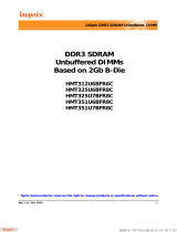
In this chapter, IDD and IDDQ measurement conditions such as test load and patterns are defined. Figure
1. shows the setup and test load for IDD and IDDQ measurements.
• IDD currents (such as IDD0, IDD1, IDD2N, IDD2NT, IDD2P0, IDD2P1, IDD2Q, IDD3N, IDD3P, IDD4R,
IDD4W, IDD5B, IDD6, IDD6ET, IDD6TC and IDD7) are measured as time-averaged currents with all
VDD balls of the DDR3 SDRAM under test tied together. Any IDDQ current is not included in IDD cur
-
rents.
• IDDQ currents (such as IDDQ2NT and IDDQ4R) are measured as time-averaged currents with all
VDDQ balls of the DDR3 SDRAM under test tied together. Any IDD current is not included in IDDQ cur
-
rents.
Attention: IDDQ values cannot be directly used to calculate IO power of the DDR3 SDRAM. They can
be used to support correlation of simulated IO power to actual IO power as outlined in Figure 2. In
DRAM module application, IDDQ cannot be measured separately since VDD and VDDQ are using one
merged-power layer in Module PCB.
For IDD and IDDQ measurements, the following definitions apply:
• ”0” and “LOW” is defined as VIN <= V
ILAC(max).
• ”1” and “HIGH” is defined as VIN >= V
IHAC(max).
• “MID_LEVEL” is defined as inputs are VREF = VDD/2.
• Timing used for IDD and IDDQ Measurement-Loop Patterns are provided in Table 1.
• Basic IDD and IDDQ Measurement Conditions are described in Table 2.
• Detailed IDD and IDDQ Measurement-Loop Patterns are described in Table 3 through Table 10.
• IDD Measurements are done after properly initializing the DDR3 SDRAM. This includes but is not lim-
ited to setting
RON = RZQ/7 (34 Ohm in MR1);
Qoff = 0
B
(Output Buffer enabled in MR1);
RTT_Nom = RZQ/6 (40 Ohm in MR1);
RTT_Wr = RZQ/2 (120 Ohm in MR2);
TDQS Feature disabled in MR1
• Attention: The IDD and IDDQ Measurement-Loop Patterns need to be executed at least one time
before actual IDD or IDDQ measurement is started.
• Define D = {CS, RAS, CAS, WE}:= {HIGH, LOW, LOW, LOW}
• Define D = {CS, RAS, CAS, WE}:= {HIGH, HIGH, HIGH, HIGH}

Rev. 1.6 / Dec. 2010 13
Figure 1 - Measurement Setup and Test Load for IDD and IDDQ (optional) Measurements
[Note: DIMM level Output test load condition may be different from above]
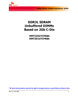
Figure 2 - Correlation from simulated Channel IO Power to actual Channel IO Power supported
by IDDQ Measurement
VDD
DDR3
SDRAM
VDDQ
RESET
CK/CK
DQS, DQS
CS
RAS, CAS, WE
A, BA
ODT
ZQ
VSS VSSQ
DQ, DM,
TDQS, TDQS
CKE
RTT = 25 Ohm
VDDQ/2
IDD
IDDQ (optional)
Application specific
memory channel
environment
Channel
IO Power
Simulation
IDDQ
Simulation
IDDQ
Simulation
Channel IO Power
Number
IDDQ
Test Load
Correction

Rev. 1.6 / Dec. 2010 14
Table 1 -Timings used for IDD and IDDQ Measurement-Loop Patterns
Table 2 -Basic IDD and IDDQ Measurement Conditions
Symbol
DDR3-1066 DDR3-1333 DDR3-1600 DDR3-1866 DDR3-2133
Unit
7-7-7 9-9-9 11-11-11 13-13-13 14-14-14
t
CK
1.875 1.5 1.25 1.07 0.935 ns
CL 7 9 11 13 14 nCK
n
RCD
7 9 11 13 14 nCK
n
RC
27 33 39 45 50 nCK
n
RAS
20 24 28 32 36 nCK
n
RP
7 9 11 13 14 nCK
n
FAW
1KB page size 20 20 24 26 27 nCK
2KB page size 27 30 32 33 38 nCK
n
RRD
1KB page size 4 4 5 5 6 nCK
2KB page size 6 5 6 6 7 nCK
n
RFC
-512Mb 48 60 72 85 97 nCK
n
RFC
-1 Gb 59 74 88 103 118 nCK
n
RFC
- 2 Gb 86 107 128 150 172 nCK
n
RFC
- 4 Gb 160 200 240 281 321 nCK
n
RFC
- 8 Gb 187 234 280 328 375 nCK
Symbol Description
I
DD0
Operating One Bank Active-Precharge Current
CKE: High; External clock: On; tCK, nRC, nRAS, CL: see Table 1; BL: 8
a)
; AL: 0; CS: High between ACT
and PRE; Command, Address, Bank Address Inputs: partially toggling according to Table 3; Data IO:
MID-LEVEL; DM: stable at 0; Bank Activity: Cycling with one bank active at a time: 0,0,1,1,2,2,... (see
Table 3); Output Buffer and RTT: Enabled in Mode Registers
b)
; ODT Signal: stable at 0; Pattern Details:
see Table 3.
I
DD1
Operating One Bank Active-Precharge Current
CKE: High; External clock: On; tCK, nRC, nRAS, nRCD, CL: see Table 1; BL: 8
a)
; AL: 0; CS: High between
ACT, RD and PRE; Command, Address; Bank Address Inputs, Data IO: partially toggling according to
Table 4; DM: stable at 0; Bank Activity: Cycling with on bank active at a time: 0,0,1,1,2,2,... (see Table
4); Output Buffer and RTT: Enabled in Mode Registers
b)
; ODT Signal: stable at 0; Pattern Details: see
Table 4.

Rev. 1.6 / Dec. 2010 15
I
DD2N
Precharge Standby Current
CKE: High; External clock: On; tCK, CL: see Table 1; BL: 8
a)
; AL: 0; CS: stable at 1; Command, Address,
Bank Address Inputs: partially toggling according to Table 5; Data IO: MID_LEVEL; DM: stable at 0;
Bank Activity: all banks closed; Output Buffer and RTT: Enabled in Mode Registers
b)
; ODT Signal: stable
at 0; Pattern Details: see Table 5.
I
DD2NT
Precharge Standby ODT Current
CKE: High; External clock: On; tCK, CL: see Table 1; BL: 8
a)
; AL: 0; CS: stable at 1; Command, Address,
Bank Address Inputs: partially toggling according to Table 6; Data IO: MID_LEVEL; DM: stable at 0;
Bank Activity: all banks closed; Output Buffer and RTT: Enabled in Mode Registers
b)
; ODT Signal: tog-
gling according to Table 6; Pattern Details: see Table 6.
I
DD2P0
Precharge Power-Down Current Slow Exit
CKE: Low; External clock: On; tCK, CL: see Table 1; BL: 8
a)
; AL: 0; CS: stable at 1; Command, Address,
Bank Address Inputs: stable at 0; Data IO: MID_LEVEL; DM: stable at 0; Bank Activity: all banks closed;
Output Buffer and RTT: Enabled in Mode Registers
b)
; ODT Signal: stable at 0; Precharge Power Down
Mode: Slow Exit
c)
I
DD2P1
Precharge Power-Down Current Fast Exit
CKE: Low; External clock: On; tCK, CL: see Table 1; BL: 8
a)
; AL: 0; CS: stable at 1; Command, Address,
Bank Address Inputs: stable at 0; Data IO: MID_LEVEL; DM: stable at 0; Bank Activity: all banks closed;
Output Buffer and RTT: Enabled in Mode Registers
b)
; ODT Signal: stable at 0; Precharge Power Down
Mode: Fast Exit
c)
I
DD2Q
Precharge Quiet Standby Current
CKE: High; External clock: On; tCK, CL: see Table 1; BL: 8
a)
; AL: 0; CS: stable at 1; Command, Address,
Bank Address Inputs: stable at 0; Data IO: MID_LEVEL; DM: stable at 0; Bank Activity: all banks closed;
Output Buffer and RTT: Enabled in Mode Registers
b)
; ODT Signal: stable at 0
I
DD3N
Active Standby Current
CKE: High; External clock: On; tCK, CL: see Table 1; BL: 8
a)
; AL: 0; CS: stable at 1; Command, Address,
Bank Address Inputs: partially toggling according to Table 5; Data IO: MID_LEVEL; DM: stable at 0;
Bank Activity: all banks open; Output Buffer and RTT: Enabled in Mode Registers
b)
; ODT Signal: stable
at 0; Pattern Details: see Table 5.
Symbol Description

Rev. 1.6 / Dec. 2010 16
I
DD3P
Active Power-Down Current
CKE: Low; External clock: On; tCK, CL: see Table 1; BL: 8
a)
; AL: 0; CS: stable at 1; Command, Address,
Bank Address Inputs: stable at 0; Data IO: MID_LEVEL; DM: stable at 0; Bank Activity: all banks open;
Output Buffer and RTT: Enabled in Mode Registers
b)
; ODT Signal: stable at 0
I
DD4R
Operating Burst Read Current
CKE: High; External clock: On; tCK, CL: see Table 1; BL: 8
a)
; AL: 0; CS: High between RD; Command,
Address, Bank Address Inputs: partially toggling according to Table 7; Data IO: seamless read data burst
with different data between one burst and the next one according to Table 7; DM: stable at 0; Bank
Activity: all banks open, RD commands cycling through banks: 0,0,1,1,2,2,...(see Table 7); Output Buffer
and RTT: Enabled in Mode Registers
b)
; ODT Signal: stable at 0; Pattern Details: see Table 7.
I
DD4W
Operating Burst Write Current
CKE: High; External clock: On; tCK, CL: see Table 1; BL: 8
a)
; AL: 0; CS: High between WR; Command,
Address, Bank Address Inputs: partially toggling according to Table 8; Data IO: seamless read data burst
with different data between one burst and the next one according to Table 8; DM: stable at 0; Bank
Activity: all banks open, WR commands cycling through banks: 0,0,1,1,2,2,...(see Table 8); Output Buf-
fer and RTT: Enabled in Mode Registers
b)
; ODT Signal: stable at HIGH; Pattern Details: see Table 8.
I
DD5B
Burst Refresh Current
CKE: High; External clock: On; tCK, CL, nRFC: see Table 1; BL: 8
a)
; AL: 0; CS: High between REF; Com-
mand, Address, Bank Address Inputs: partially toggling according to Table 9; Data IO: MID_LEVEL; DM:
stable at 0; Bank Activity: REF command every nREF (see Table 9); Output Buffer and RTT: Enabled in
Mode Registers
b)
; ODT Signal: stable at 0; Pattern Details: see Table 9.
I
DD6
Self-Refresh Current: Normal Temperature Range
T
CASE
: 0 - 85
o
C; Auto Self-Refresh (ASR): Disabled
d)
;Self-Refresh Temperature Range (SRT): Normal
e)
;
CKE: Low; External clock: Off; CK and CK
: LOW; CL: see Table 1; BL: 8
a)
; AL: 0; CS, Command, Address,
Bank Address Inputs, Data IO: MID_LEVEL; DM: stable at 0; Bank Activity: Self-Refresh operation; Out-
put Buffer and RTT: Enabled in Mode Registers
b)
; ODT Signal: MID_LEVEL
I
DD6ET
Self-Refresh Current: Extended Temperature Range (optional)
f)
T
CASE
: 0 - 95
o
C; Auto Self-Refresh (ASR): Disabled
d)
;Self-Refresh Temperature Range (SRT): Extend-
ed
e)
; CKE: Low; External clock: Off; CK and CK: LOW; CL: see Table 1; BL: 8
a)
; AL: 0; CS, Command,
Address, Bank Address Inputs, Data IO: MID_LEVEL; DM: stable at 0; Bank Activity: Extended Tempera-
ture Self-Refresh operation; Output Buffer and RTT: Enabled in Mode Registers
b)
; ODT Signal:
MID_LEVEL
Symbol Description

Rev. 1.6 / Dec. 2010 17
a) Burst Length: BL8 fixed by MRS: set MR0 A[1,0]=00B
b) Output Buffer Enable: set MR1 A[12] = 0B; set MR1 A[5,1] = 01B; RTT_Nom enable: set MR1 A[9,6,2] = 011B;
RTT_Wr enable: set MR2 A[10,9] = 10B
c) Precharge Power Down Mode: set MR0 A12=0B for Slow Exit or MR0 A12 = 1B for Fast Exit
d) Auto Self-Refresh (ASR): set MR2 A6 = 0B to disable or 1B to enable feature
e) Self-Refresh Temperature Range (SRT): set MR2 A7 = 0B for normal or 1B for extended temperature range
f) Read Burst Type: Nibble Sequential, set MR0 A[3] = 0B
I
DD6TC
Auto Self-Refresh Current (optional)
f)
T
CASE
: 0 - 95
o
C; Auto Self-Refresh (ASR): Enabled
d)
;Self-Refresh Temperature Range (SRT): Normal
e)
;
CKE: Low; External clock: Off; CK and CK: LOW; CL: see Table 1; BL: 8
a)
; AL: 0; CS, Command, Address,
Bank Address Inputs, Data IO: MID_LEVEL; DM: stable at 0; Bank Activity: Auto Self-Refresh operation;
Output Buffer and RTT: Enabled in Mode Registers
b)
; ODT Signal: MID_LEVEL
I
DD7
Operating Bank Interleave Read Current
CKE: High; External clock: On; tCK, nRC, nRAS, nRCD, NRRD, nFAW, CL: see Table 1; BL: 8
a), f)
; AL: CL-
1; CS
: High between ACT and RDA; Command, Address, Bank Address Inputs: partially toggling accord-
ing to Table 10; Data IO: read data burst with different data between one burst and the next one
according to Table 10; DM: stable at 0; Bank Activity: two times interleaved cycling through banks (0,
1,...7) with different addressing, wee Table 10; Output Buffer and RTT: Enabled in Mode Registers
b)
;
ODT Signal: stable at 0; Pattern Details: see Table 10.
Symbol Description

Rev. 1.6 / Dec. 2010 18
Table 3 - IDD0 Measurement-Loop Pattern
a)
a) DM must be driven LOW all the time. DQS, DQS are MID-LEVEL.
b) DQ signals are MID-LEVEL.
CK, CK
CKE
Sub-Loop
Cycle
Number
Command
CS
RAS
CAS
WE
ODT
BA[2:0]
A[15:11]
A[10]
A[9:7]
A[6:3]
A[2:0]
Data
b)
toggling
Static High
0
0
ACT001100000000 -
1,2 D, D100000000000 -
3,4 D
, D 111100000000 -
... repeat pattern 1...4 until nRAS - 1, truncate if necessary
nRAS PRE001000000000 -
... repeat pattern 1...4 until nRC - 1, truncate if necessary
1*nRC+0 ACT 0 0 1 1 0 0 00 0 0 F 0 -
1*nRC+1, 2 D, D 1 0 0 0 0 0 00 0 0 F 0 -
1*nRC+3, 4 D
, D 1111000000F0 -
... repeat pattern 1...4 until 1*nRC + nRAS - 1, truncate if necessary
1*nRC+nRAS PRE 0 0 1 0 0 0 00 0 0 F 0 -
... repeat pattern 1...4 until 2*nRC - 1, truncate if necessary
1 2*nRC repeat Sub-Loop 0, use BA[2:0] = 1 instead
2 4*nRC repeat Sub-Loop 0, use BA[2:0] = 2 instead
3 6*nRC repeat Sub-Loop 0, use BA[2:0] = 3 instead
4 8*nRC repeat Sub-Loop 0, use BA[2:0] = 4 instead
5 10*nRC repeat Sub-Loop 0, use BA[2:0] = 5 instead
6 12*nRC repeat Sub-Loop 0, use BA[2:0] = 6 instead
7 14*nRC repeat Sub-Loop 0, use BA[2:0] = 7 instead

Rev. 1.6 / Dec. 2010 19
Table 4 - IDD1 Measurement-Loop Pattern
a)
a) DM must be driven LOW all the time. DQS, DQS are used according to RD Commands, otherwise MID-LEVEL.
b) Burst Sequence driven on each DQ signal by Read Command. Outside burst operation, DQ signals are MID_LEVEL.
CK, CK
CKE
Sub-Loop
Cycle
Number
Command
CS
RAS
CAS
WE
ODT
BA[2:0]
A[15:11]
A[10]
A[9:7]
A[6:3]
A[2:0]
Data
b)
toggling
Static High
0
0
ACT 0 0 1 1 0 0 00 0 0 0 0 -
1,2 D, D 1 0 0 0 0 0 00 0 0 0 0 -
3,4 D
, D 11110000000 0 -
... repeat pattern 1...4 until nRCD - 1, truncate if necessary
nRCD RD 0 1 0 1 0 0 00 0 0 0 0 00000000
... repeat pattern 1...4 until nRAS - 1, truncate if necessary
nRAS PRE 0 0 1 0 0 0 00 0 0 0 0 -
... repeat pattern 1...4 until nRC - 1, truncate if necessary
1*nRC+0 ACT 0 0 1 1 0 0 00 0 0 F 0 -
1*nRC+1,2 D, D 1 0 0 0 0 0 00 0 0 F 0 -
1*nRC+3,4 D
, D 1111000000F 0 -
... repeat pattern nRC + 1,...4 until nRC + nRCE - 1, truncate if necessary
1*nRC+nRCD RD 0 1 0 1 0 0 00 0 0 F 0 00110011
... repeat pattern nRC + 1,...4 until nRC + nRAS - 1, truncate if necessary
1*nRC+nRAS PRE 0 0 1 0 0 0 00 0 0 F 0 -
... repeat pattern nRC + 1,...4 until *2 nRC - 1, truncate if necessary
1 2*nRC repeat Sub-Loop 0, use BA[2:0] = 1 instead
2 4*nRC repeat Sub-Loop 0, use BA[2:0] = 2 instead
3 6*nRC repeat Sub-Loop 0, use BA[2:0] = 3 instead
4 8*nRC repeat Sub-Loop 0, use BA[2:0] = 4 instead
5 10*nRC repeat Sub-Loop 0, use BA[2:0] = 5 instead
6 12*nRC repeat Sub-Loop 0, use BA[2:0] = 6 instead
7 14*nRC repeat Sub-Loop 0, use BA[2:0] = 7 instead

Rev. 1.6 / Dec. 2010 20
Table 5 - IDD2N and IDD3N Measurement-Loop Pattern
a)
a) DM must be driven LOW all the time. DQS, DQS are MID-LEVEL.
b) DQ signals are MID-LEVEL.
Table 6 - IDD2NT and IDDQ2NT Measurement-Loop Pattern
a)
a) DM must be driven LOW all the time. DQS, DQS are MID-LEVEL.
b) DQ signals are MID-LEVEL.
CK, CK
CKE
Sub-Loop
Cycle
Number
Command
CS
RAS
CAS
WE
ODT
BA[2:0]
A[15:11]
A[10]
A[9:7]
A[6:3]
A[2:0]
Data
b)
toggling
Static High
0
0
D10000000000 -
1D10000000000-
2D
1111000 0 0 F0 -
3D
1111000 0 0 F0 -
1 4-7 repeat Sub-Loop 0, use BA[2:0] = 1 instead
2 8-11 repeat Sub-Loop 0, use BA[2:0] = 2 instead
3 12-15 repeat Sub-Loop 0, use BA[2:0] = 3 instead
4 16-19 repeat Sub-Loop 0, use BA[2:0] = 4 instead
5 20-23 repeat Sub-Loop 0, use BA[2:0] = 5 instead
6 24-17 repeat Sub-Loop 0, use BA[2:0] = 6 instead
7 28-31 repeat Sub-Loop 0, use BA[2:0] = 7 instead
CK, CK
CKE
Sub-Loop
Cycle
Number
Command
CS
RAS
CAS
WE
ODT
BA[2:0]
A[15:11]
A[10]
A[9:7]
A[6:3]
A[2:0]
Data
b)
toggling
Static High
0
0
D10000000000 -
1D10000000000-
2D
1111000 0 0 F0 -
3D
1111000 0 0 F0 -
1 4-7 repeat Sub-Loop 0, but ODT = 0 and BA[2:0] = 1
2 8-11 repeat Sub-Loop 0, but ODT = 1 and BA[2:0] = 2
3 12-15 repeat Sub-Loop 0, but ODT = 1 and BA[2:0] = 3
4 16-19 repeat Sub-Loop 0, but ODT = 0 and BA[2:0] = 4
5 20-23 repeat Sub-Loop 0, but ODT = 0 and BA[2:0] = 5
6 24-17 repeat Sub-Loop 0, but ODT = 1 and BA[2:0] = 6
7 28-31 repeat Sub-Loop 0, but ODT = 1 and BA[2:0] = 7
/