Faithfull FAI KWJPRO Owner's manual

Type
Owner's manual

This manual is also suitable for

Faithfull FAI KWJPRO is an advanced worktop jig designed for precise cutting and joining of kitchen countertops. With its versatile features, it enables you to create a range of cuts, including 90° corners, corner cooking solutions, and joining bolt slots. The jig's unique quick reference guide and comprehensive labeling system provide easy use without constant reference to instructions. It accommodates various worktop thicknesses and allows for adjustments to accommodate out-of-square walls. The jig ensures accurate and professional-looking results for your kitchen worktop installations.

Faithfull FAI KWJPRO is an advanced worktop jig designed for precise cutting and joining of kitchen countertops. With its versatile features, it enables you to create a range of cuts, including 90° corners, corner cooking solutions, and joining bolt slots. The jig's unique quick reference guide and comprehensive labeling system provide easy use without constant reference to instructions. It accommodates various worktop thicknesses and allows for adjustments to accommodate out-of-square walls. The jig ensures accurate and professional-looking results for your kitchen worktop installations.

PRO JIG INSTRUCTIONS
1.00 General Information
1.01 Introduction
The PRO Jig is the most advanced design of worktop jig available. Your jig will allow you to
complete a range of cuts and incorporates other design features allowing you to use the jig as a
straight edge and as a radius guide.
The Jig also has a unique quick reference guide to the various types of cut engraved on the face
and a comprehensive system of labels to allow easy use without constant reference to the written
instructions.
1.02 What you will need
In addition to the jig and the pegs provided, you require:
A plunge action router of at least 1500w rating
A sharp 12.7mm diameter cutter, 50mm length blade
A 30mm guide bush
Two quick release or G-Clamps
1.03 Before you start
Please take some time to read through these instructions and always practice on offcuts until you
achieve a satisfactory result. Please observe all relevant safety requirements for the use of
routers and never lift the router away from the jig until the cutter has stopped rotating and is fully
retracted.
1.04 How the jig works
Depending on the particular cut required, the pegs are placed in the holes indicated in the
instructions. The jig is offered up to the worktop and clamped in position. The jig is then used to
guide the router. Most cuts are made in stages with the waste being progressively removed,
followed by a final stroke which provides a perfect finished edge.
1.05 Conventions and important points
All references to left and right hand joints in these instructions use the convention described
in the diagram engraved on the face of the jig.
Always use a sharp cutter and ensure the guide bush is firmly attached to the base plate.
Always work from left to right never the other way round.
Make sure the pegs are well seated and are not proud of the surface of the jig.
Wherever you see letters in italics on the jig (e.g. LF), this is a reminder that this cut is
performed with the worktop face down.
The holes surrounded by a square indicate that a peg should not be inserted from this side
when performing any of the cuts.
When working with the centre slot the side nearest you is always used first for the waste
removal followed by the side furthest from you for the finished edge.
2
When clamping in position check the pegs are still in contact with the worktop as certain types
of clamp can cause the jig to creep out of position if over tightened.
The guide bush should be set to a depth of 11mm to allow maximum contact with the jig
without fouling the worktop surface.
Take care to ensure the router remains absolutely perpendicular when performing all cuts;
this is particularly important when performing cuts with the worktop face down.
The bolt slots will accommodate most common patterns of 150mm joining bolt.
When making many of the cuts you may find it more convenient to remove larger pieces of
waste with a jigsaw prior to making the router cuts. This is particularly relevant when you are
unable to support waste which would fall away in the cutting process.
It is important that you
work the router from left to
right. To work the router
right to left means working
against the cutter’s
direction, which will cause
the router to travel away
from you and may damage
the jig or even cause
injury.
2.00 90° Corner Joints
2.01 90° Corner-Right-hand female cut
With the jig logo side up, place a peg in the length stop hole which matches the width of male section of worktop you
wish to set in. Place pegs in all holes marked RF+LF to the left of the length stop peg. With the worktop face-up
offer the jig against the post form edge and rest the length stop peg against the right-hand edge of the worktop.
Ensure all pegs are touching the worktop and clamp in position then check again.
35mm
POSTFORMED EDGE
RIGHT HAND FEMALE
Fig. 1
3
Position the router in extreme bottom left-hand point of the centre slot. Set the cutting depth to 10-15mm and start
the router. Pass the router steadily along the centre slot using the side of the slot nearest you to guide the router.
Repeat this process increasing the depth of cut by 10-15mm for each pass until the post-form edge has been
removed. With the cutter set to maximum depth but this time using the side of the slot furthest from you to guide the
router, make one final pass which will remove approximately 1mm leaving a perfectly cut edge.
Note These instructions set up the jig to cut 90° corners. If you wish to allow for slightly out of square walls, remove
1 or more of the RF+LF pegs and adjust the angle of the jig against the post-form edge. More substantial
movements out of square require a corresponding adjustment when cutting the male component. You should be
fully conversant with the usual functions of the jig before attempting this type of adjustment.
2.02 90° Corner - Left-hand female cut
Place the worktop face-down, post-form edge towards you and follow the instructions as per
2.01.
35mm
LEFT HAND FEMALE
Fig. 2
POSTFORMED EDGE
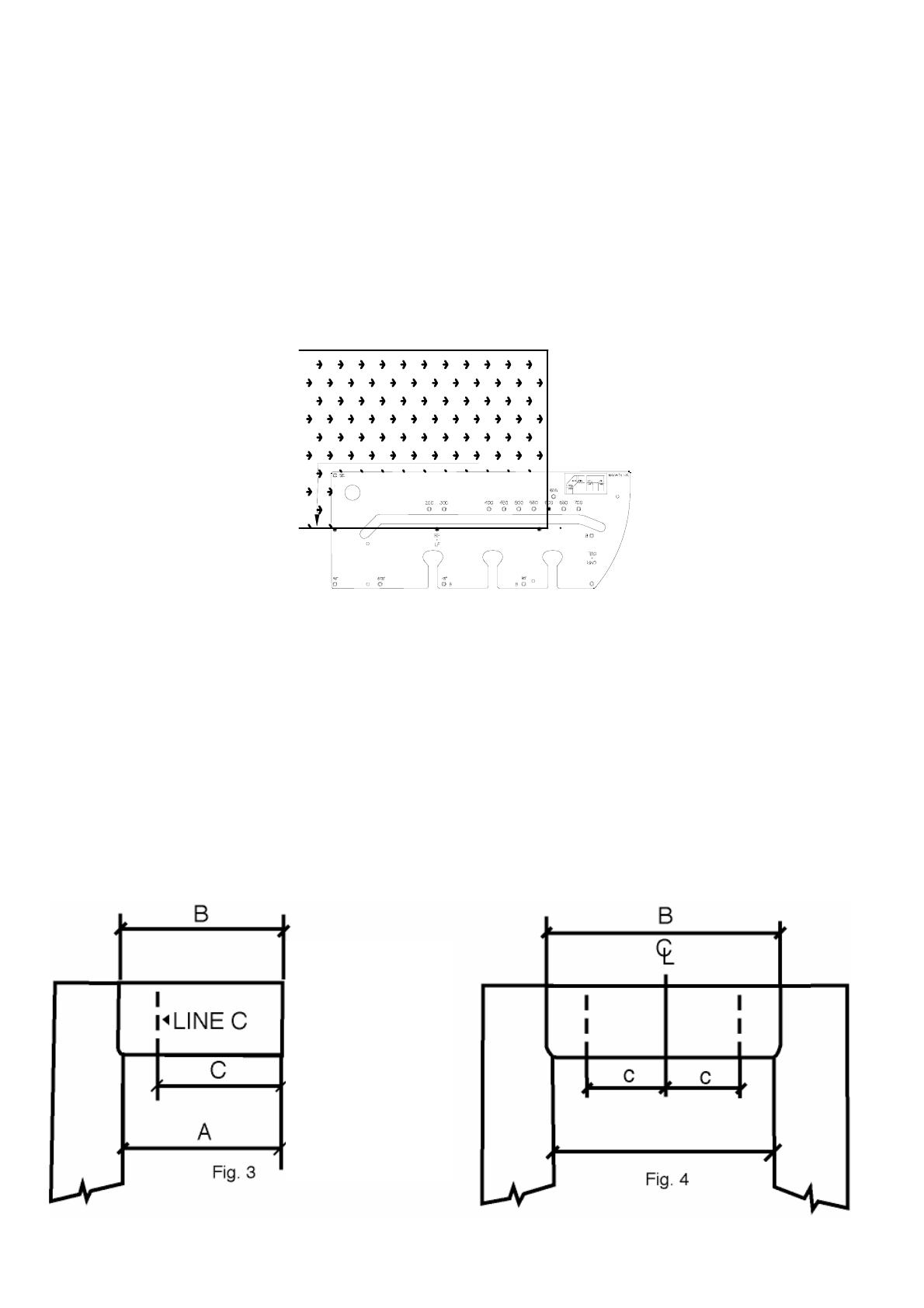
2.03 Measuring & cutting the male component to length
The diagram engraved on each face of the jig depicts the optimum layout for worktops fitted to 3
walls. This arrangement is easy to measure and leaves the greatest margin to recover from mis-
measures. If, however you are forced to arrange the worktops as per fig 4, you should carefully
read the following instructions. Please exercise extreme caution when cutting the centre section
of fig 4.
Your jig will inset one worktop 35mm into the post-form edge of the other. When measuring up
an allowance must be made for this on the male section of the worktop. Refer to the two
diagrams below to help calculate your measurements fig. 3 & 4.
A+35mm = B
B-224 = C
4
2.04 90° Corner - Right-hand male cut
Place the worktop face down. Turn the jig logo side down and place 4 pegs in the holes marked
RM+LM and offer firmly up against the post-form edge fig. 5. Using the measurements
calculated in the above section, mark line C on the worktop in pencil and align the bottom edge of
the jig with this position. Clamp in position and check again to ensure all pegs are in contact with
the post-form edge and the jig is in position.
Position the router in extreme top left-hand
point of the centre slot. Set the cutting depth
to 10-15mm and start the router. Pass the
router steadily along the centre slot using the
side of the slot nearest you to guide the router.
Repeat this process increasing the depth of
cut by 10-15mm for each pass until the waste
has been removed. With the cutter set to
maximum depth but this time using the side of
the slot furthest from you to guide the router,
make one final pass which will remove
approximately 1mm, leaving a perfectly cut
edge.
RIGHT HAND MALE
Line C in pencil
Line C in pencil
Postformed Edge
Fig. 5
2.05 90° Corner - Left-hand male cut
LEFT HAND MALE
POST FORMED EDGE
Line C in Pencil
Line C in Pencil
Place the worktop face up and follow the instructions in 2.04.
5
2.06 Joining bolt slots in 90° Females
Place the worktop face down. The jig should be logo side down right-hand females (RF) as
below, or logo side up for left-hand females (LF). Place pegs in the holes marked B.
Fig. 6
Offer the jig up to the worktop and clamp into position. Set your plunging depth to about 20mm.
You should ensure this is sufficient to accommodate your joining bolt. Now use each mushroom
shaped recess to guide the router. Working clockwise around the slot, remove all the waste.
Note; worktop widths 400-550mm will only accommodate 2 slots.
2.07 Joining bolt slots in 90° Males
Place the worktop face down. The jig should be logo side up for right-hand males (RM)
{illustrated} or log side down for left-hand males (LM). Place 4 pegs in the holes marked B.
Follow the routing instructions in 2.06
35mm
Po
s
t
f
o
rm
e
d
Ed
g
e
Fig. 7
2.08 Connecting the worktops
Carefully maneuver the worktops into position taking great care not to allow the routed face of
each component to damage the other. Connect using 150mm joining bolts and ColorFill ®.
6
3.00 Corner cooking solution joints
The following instructions are based on 570mm deep carcasses and 600mm wide tops. The
resulting corner will accommodate a 600mm wide corner unit. The minimum length of worktop
required for the corner piece is 1600mm. The inset is 13mm.
Fig. 8
3.01 Corner Cooking Solution - Right-hand Female (CFR)
Place the worktop centre piece face-up; mark a centre line in the middle and mark two lines
640mm either side on the back edge of the worktop. Tip: the jig used in straight edge mode can
help greatly with your marking out on this type of corner, see 4.01.
With the jig logo side down, place 3 pegs in the holes marked CFR+CFL. Offer the jig up against
the post-form edge and align the top edge of the jig with the right-hand 640mm mark. Clamp in
position and check again for correct alignment. Follow the cutting instructions for 90° Females.
When complete remove the jig. Measure 600mm from the post-form edge as per fig 10 and
accurately remove this section using a saw.
7
C
L
640 640
min
1600
Peg
Peg
Fig. 9
Fig. 10
3.02 Corner Cooking Solution - Left-hand Female
(CFL)
Turn the worktop centre piece face down and follow the instructions in 3.01.
3.03 Corner Cooking Solution - Right-hand Male
(CMR)
Place the worktop face down. With the jig logo-side up place 4 pegs in the holes labeled
CMR+CML fig 11. Follow the routing instructions in 2.04.
3
5
m
m
Fig. 11
P
o
s
t
f
o
r
m
e
d
E
d
g
e
3.04 Corner Cooking Solution - Left-hand Male (CML)
Place the worktop face up and follow instructions as per 3.03
3.05 Corner Cooking Solution - Female bolt slots
Place the centre piece face down. The jig should be logo side up for left-hand females (CFL) fig
12 or logo side down for right-hand females (CFR) not shown. Place 4 pegs in the holes marked
B and offer the jig up against the cut face as per the diagram below. Follow the routing
instructions as per 2.06.
3
5
m
m
Left-hand Female (CFL)
P
e
g
P
e
g
P
e
g
Fig. 12
3.05 Corner Cooking Solutions - Male bolt slots
Follow the instructions as per 2.07
4.00 Other functions of your jig
8
4.01 Straight edge mode
Your jig can help you mark off, quickly and accurately, common angles. It can also act as a
guide for various types of power tool.
To use your jig in this mode place 1 peg in the hole marked SE and another in one of the angle
holes arranged along the bottom edge 90°, 67.5°, 45° or 30°. Offer the jig up against the work.
Clamp in position and use the top edge as the straight edge.
35mm
Fig. 13
4.02 Breakfast bar radius end mode
The jig can be used as a guide when adding a radius to the end of a worktop or panel. You may
use any of the 3 horizontal arrays of holes indicated in fig 14 for the pegs. Mark out in pencil
using the radius edge as a guide and remove the waste with a jigsaw. Set the jig up again,
clamp in position and use the router to remove no more than one quarter of the cutter’s diameter
to leave a perfectly finished edge. Extreme caution should be exercised when attempting this
type of cut - your router can easily tip causing damage or injury.
35mm
Fig. 14
5.00 Troubleshooting Guide
9
10
From listening to Kitchen Fitters and Carpenters over the years we have compiled this guide to
help you overcome the more common faults encountered. Used correctly, your jig will give
perfect results every time.
Problem
Poor finish on male/female
joint faces.
Sharp angle near post-form
edge on male/female
Good finish but male &
female don’t match up.
Inconsistent results -
wandering edges.
Irregular gaps on RH male
and/or LH female face.
Probable Cause
Incomplete routing process.
Incorrect size of cutter and/or
guide bush.
Loose guide bush.
Poor router control.
Remedy
Ensure final stroke against
far edge of centre slot is
performed.
Ensure final stroke against
far edge is performed.
Ensure 12.7mm cutter and
30mm guide bush - nothing
else is suitable.
Ensure guide bush is firmly
attached to the router base.
Ensure the cutter remains
absolutely perpendicular on
these cuts.
  • Page 1 1
  • Page 2 2
  • Page 3 3
  • Page 4 4
  • Page 5 5
  • Page 6 6
  • Page 7 7
  • Page 8 8
  • Page 9 9
  • Page 10 10

Faithfull FAI KWJPRO Owner's manual

Type
Owner's manual
This manual is also suitable for

Faithfull FAI KWJPRO is an advanced worktop jig designed for precise cutting and joining of kitchen countertops. With its versatile features, it enables you to create a range of cuts, including 90° corners, corner cooking solutions, and joining bolt slots. The jig's unique quick reference guide and comprehensive labeling system provide easy use without constant reference to instructions. It accommodates various worktop thicknesses and allows for adjustments to accommodate out-of-square walls. The jig ensures accurate and professional-looking results for your kitchen worktop installations.

Ask a question and I''ll find the answer in the document

Finding information in a document is now easier with AI