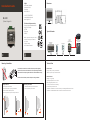
iLight SI-2-D is a system integrator that provides an RS232 link for connecting serial devices to an iLight Network. It enables communication between iLight devices and external systems, allowing for control and monitoring of lighting systems. With a maximum segment distance of 500 meters and support for up to 100 devices per segment, the SI-2-D offers flexibility and scalability for various lighting projects.
iLight SI-2-D is a system integrator that provides an RS232 link for connecting serial devices to an iLight Network. It enables communication between iLight devices and external systems, allowing for control and monitoring of lighting systems. With a maximum segment distance of 500 meters and support for up to 100 devices per segment, the SI-2-D offers flexibility and scalability for various lighting projects.


-
 1
1
-
 2
2


iLight SI-2-D is a system integrator that provides an RS232 link for connecting serial devices to an iLight Network. It enables communication between iLight devices and external systems, allowing for control and monitoring of lighting systems. With a maximum segment distance of 500 meters and support for up to 100 devices per segment, the SI-2-D offers flexibility and scalability for various lighting projects.
Ask a question and I''ll find the answer in the document
Finding information in a document is now easier with AI
Related papers
Other documents
-
Eaton EG2-NA Installation guide
-
-
-
-
-
-
-
Cooper TSE55-B Installation guide
-
Detecto 825-iCAN User manual
-