Page is loading ...

P1
Document 9850-000521-00
Introduction
The DALI control panel provides complete
control of pre-programmed lighting scenes
within a DALI lighting control system. The
adaptable design allows you to choose from
a range of button combinations, which can be
tted and changed at any time. Where tted,
raise and lower buttons compliment the usual
selection buttons to allow immediate changes to
the intensity of any scene.
DALI Control Panel
Installation guide
Supplied parts
Front Cover
Back Plate
Button Assembly
Screw holes for attaching
to wall box
Dimensions
The DALI control panel ts into a single gang UK style
wall box with a minimum internal depth of 47mm.
With control panel disassembled (see above), use the
two supplied long screws to secure the back plate to
the wall box.
Fixing to a wallbox

P2
Document 9850-000521-00
Removing Face Plate from the DALI Control Panel
1. On the underside of the face plate, beneath the lower buttons, locate the small central recess. Carefully insert a
small implement (such as a pen or screwdriver) into the recess and lever the front cover gently away from the back
plate.
Changing buttons
The DALI control panel allows you to change the buttons in order to
customize its appearance.
1. Remove the face plate as illustrated.
2. Locate the four clips (two on each side) of the button frame. Carefully
press in all four clips to disenage the button frame and pull the frame away
from the main body.
3. You can now remove the buttons from the frame and replace them (and
the frame), as necessary.
4. With the new buttons in place within the frame, align its clips with the
four holes of the main body and press it into place so that all four clips
click as they lock.
3. Store face plate safe from damage.
2. Unclip the face plate from the back plate.

P3
Document 9850-000521-00
Scene Selection
To select a scene press one of the buttons identied by either a number,
indicated by a specic legend or that is blank.
To turn lights off press the button marked Off or O on button only panels or
the light bulb symbol on control panels tted with the ‘On, Off, Raise and
Lower’ button set.
To raise the level of scene press (when tted).
To lower the level of scene press (when tted).
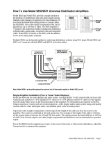
Control wiring
The DALI Control Panel is provided with 2 x polarity-free wires used to connect to the DALI line.
Standard Recommended DALI cabling: 2-core cable of minimum gauge 1.5 mm
2
.
The total cable distance: 300m.
2 x polarity-free wires
The front cover plate should only be cleaned gently with a clean, damp
cloth. Abrasive cleaners, polishes, solvent based cleaning agents, or alkali
based cleaners should not be used.
‘Scene Only’
control panel
example
Control panel
tted with ‘On,
Off, Raise, Lower’
button set
Care and Maintenance
Typical DALI line schematic
DALI Bus
iCANnet
SOURCE CONTROLLER
SCMD4
DALI DINRAIL
SOURCE CONTROLLER
DALI
CONTROL
PANEL
CONTROL
PANEL
DALI
MULTI
SENSOR
DALI
DAC
0-10V VDC
DALI
DIMMABLE
BALLAST
DALI
RELAY
CONTROLLER
Max. 64 devices
per DALI loop.
Max. length 300M
1.5mm2 cable

P4
Document 9850-000521-00
iLight Series
Eaton Lighting Systems
20 Greenhill Crescent, Watford Business Park
Watford, Herts, WD18 8JA. UK
T: +44 (0)1923 495496
F: +44 (0)1923 228796
www.iLight.co.uk
Technical Support
For technical support contact your local installer or distributor
T: +44 (0)844 32 49 100
International Headquarters
Usk House, Lakeside, Llantarnam Park,
Cwmbran, NP44 3HD. UK
T: +44 (0)1923 495495
F: +44 (0)1633 867880
www.eatonlightingsystems.com
All products manufactured by Cooper Controls Ltd and identied with the iLight brand are warranted to be free from de-
fects in material and workmanship and shall conform to and perform in accordance with Seller’s written specications.
For detailed warranty information, visit our website at www.coopercontrol.com
This warranty will be limited to the repair or replacement, at Seller’s discretion, of any such goods found to be defective,
upon their authorised return to Seller. This limited warranty does not apply if the goods have been damaged by accident,
abuse, misuse, modication or misapplication, by damage during shipment or by improper service.
There are no warranties, which extend beyond the hereinabove-limited warranty, INCLUDING, BUT NOT LIMITED TO,
THE IMPLIED WARRANTY OF MERCHANTABILITY AND THE IMPLIED WARRANTY OF FITNESS.
No employee, agent, dealer, or other person is authorized to give any warranties on behalf of the Seller or to assume
for the Seller any other liability in connection with any of its goods except in writing and signed by the Seller. The Seller
makes no representation that the goods comply with any present or future federal, state or local regulation or ordinance.
Compliance is the Buyer’s responsibility.
The use of the Seller’s goods should be in accordance with the provision of the National Electrical Code, UL and/or other
industry or military standards that are pertinent to the particular end use. Installation or use not in accordance with these
codes and standards could be hazardous.
!
WARNING HAZARDOUS VOLTAGES
DISCONNECT FROM SUPPLY
BEFORE REMOVING COVERS
NO USER SERVICEABLE PARTS INSIDE
SERVICE BY QUALIFIED PERSONNEL ONLY
WARNING
To reduce the risk of fire or electric shock,
DO NOT expose this device to rain or moisture.
DO NOT energise unless the front cover is in place.
This device must be earthed.
Installation, programming and maintenance must be carried out by qualified personnel.
Cooper Controls cannot accept responsibility for repairs or modifications that are not
competently executed and in accordance with service or upgrade information.
CE compliant to all relevant standards
DALI Control Panel
Installation guide
/