Page is loading ...

Note
Save all packing materials. If you
need to ship the Phantom II in
the future, repack the unit in its
original packaging to prevent
shipping damage.
Phantom II
S
tereo Preamplifier
QUICK SETUP GUIDE
Getting Started
Thank you for your purchase of the Krell Phantom II Stereo Preamplifier. The Phantom II
features Krell Current Mode circuit topologies, Krell CAST technology, and a robust
power supply for exceptional audio performance. A thoughtful suite
of menu options ensures that the Phantom II can be customized for the greatest
e
ase of operation.
Please contact your authorized dealer, distributor, or Krell if you have any questions
not addressed in the owner’s reference.
The preamplifier’s front panel provides power on, input and zone selection, level
control, menu functions, and status display. The rear panel allows connection to
audio sources, power amplifiers, AC power, and other system components.
The remote control provides power, preamplifier, level control, navigation and
customization functions, CD and DVD player controls and menu configuration.
Do not place the preamplifier where it could be exposed to dripping or splashing.
Do not remove or bypass the ground pin on the end of the AC cord. This may cause radio fre-
quency interference (RFI) to be introduced into your playback system.
The ventilation grids on the top and bottom of the preamplifier must be unobstructed at all
times during operation. Do not place flammable material on top of or beneath the component.
Turn off all systems’ power before connecting the preamplifier to any component.
Make sure all cable terminations are of the highest quality, free from frayed ends, short circuits,
or cold solder joints.
THERE ARE NO USER-SERVICEABLE PARTS INSIDE ANY KRELL PRODUCT
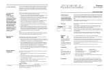
1. Open the shipping box and remove the top layer of foam. You will see these
items:
2. Carefully remove all items from the shipping box.
3.
Place the preamplifier in a safe location and r
emove the protective plastic wrap
-
ping.
We recommend that you place the preamplifier on a firm, level surface, away from
excessive heat, humidity
, or moisture. The preamplifier requires at least two inches
(5 cm) of clearance on each side and at least two inches (5 cm) of clearance above
to pr
ovide adequate ventilation. Installations inside cabinetry may need extra ventila
-
tion.
The Phantom II preamplifier has superb regulation and does not require a dedicated
AC circuit. Avoid connections through extension cords or multiple AC adapters.
High quality 15 amp AC strips ar
e acceptable. The use of AC line conditioning
devices is not recommended. The features provided by these devices are already on
board the Phantom II.
WARNINGS
Krell Phantom II 1
Unpacking
Krell Industries, LLC., 45 Connair Road,Orange, CT 06477-3650 USA
TEL 203-298-4000, FAX 203-891-2028, E-MAIL [email protected]
WEB SITE http://www
.kr
ellonline.com
Connecting the
Phantom II
to Your System
Position the preamplifier where you intend to use it in your system.
1. Neatly arrange and organize wiring to and from the preamplifier and all compo-
nents. Separate the AC wires from any audio cables to prevent hum or other
u
nwanted noise from being introduced into the system.
2. Connect the outputs of your source equipment to the appropriate CAST (18),
balanced (15), single-ended (16), or tape inputs (17) on the Phantom II.
3. Connect the main outputs (20) on the Phantom II to your amplifier’s inputs.
4. Connect the supplied AC power cord to the IEC power cord receptacle (26)
o
f the preamplifier.
5. Plug the other end of the AC power cord into AC power. The display (3) scrolls
through
P
HANTOM II SOFTWARE VERSION
, and the stand-by/power LED (7) illumi-
nates red, indicating that the Phantom II is in stand-by mode. When the
scrolling stops, the Phantom II is ready to be powered on.
Note
Use only the power cord provided with the Phantom II to make the connection to AC power.
Operation with a power cor
d other than the one supplied by Krell can induce noise, limit cur-
rent, or otherwise impair the ability of the preamplifier to perform optimally.
After the Phantom II is connected to your system and to AC power, and the front
panel display has stopped scrolling, begin operation:
1. Press the power button (1) on the front panel, or the remote control power key.
The standby/power LED turns blue. The display shows the factory default input:
S-1, and level: -inf. The Phantom II is now in the operational mode.
2. With the preamplifier output muted, or the volume fully attenuated, select a
source manually using the front panel input select buttons (8, 9, or 10) or the
remote input select keys. Start playing the source. Use the level control knob
(14) or the remote level keys to set the volume to a comfortable level.
3. To return the preamplifier to the stand-by mode, press the power button (1) or
remote power key. (We recommend leaving the Phantom II in the stand-by
mode when it is not playing music.)
The balance function allows adjustment of the left and right balance. The options
are:
CENTER, L .5-5 dB <, R .5-5 dB >.
1. Press the preamplifier menu button (5), then use the level control knob, or the
remote control up and down keys to select:
BALANCE.
2. Press the enter button (6) or remote enter key. The display shows the default
mode:
CENTER.
3. Use the level control knob, or the up and down keys, to select the desired bal-
ance option from 0 to +5 dB in .5 dB increments, left or right.
4.
Press the enter button or key to confirm the selection. The display r
eads:
BALANCE.
5. Press the menu button to exit the menu.
4 Krell Phantom II
Operating the
Phantom II
This product complies with the EMC directive (89/336/EEC)
and the low-voltage directive (73/23/EEC).
1 Preamplifier chassis
1 IEC connector (AC power) cord
1 Remote contr
ol
2 AAA remote batteries
1 T
-10 T
orx wrench for remote
1 Quick Setup Guide
Placement
AC POWER GUIDELINES
MODEL
SERIAL NUMBER
Phantom II Pr
eamplifier
Overview
The owner’s reference for this
product, including a detailed
description of features, technolo-
gies, and warranty is available on
the web at: www.krellonline.com
Channel Balance
Adjustment
Krell recommends using its
proprietary Krell CAST system
for unparalleled sonic perfor-
mance for connections
between the preamplifier and
other CAST-equipped compo-
nents. Krell CAST uses flexible
interconnecting cables that
can be drawn through tight
spaces and concealed.
The Phantom II also offers bal-
anced operation. This not only
minimizes sonic loss but is
also immune to induced noise,
especially for installations
using long cables.
K RELL
THE LEADER IN AUDIO ENGINEERING

2 Krell Phantom II Krell Phantom II 3
Figure 1 The Phantom II Front Panel
Figure 2 The
Phantom II
Remote Control
Figure 3 The Phantom II Back Panel
KRELL
This pr
oduct is manufactured in the United States of America. Krell
®
is a r
egistered trademark of Krell Industries, LLC., and is restricted for
use by Krell Industries, LLC. its subsidiaries, and authorized agents. Krell Current Mode™ and Evolution CAST™ are trademarks of Krell
Industries, LLC. All other trademarks and trade names are registered to their respective companies.
© 2011 by Krell Industries, LLC., All rights reserved.
Front Panel
Back Panel
15 Balanced inputs: B-1
and B-2
These XLR balanced
analog source input
connectors are wired
as follows:
Pin 1 Ground
Pin 2 Non-inverting
Pin 3 Inverting
16 Single-ended inputs:
S-1, S-2, and S-3
There are 3 single-
ended analog source
inputs with RCA con-
nector pairs.
Customizing the
Phantom II
Configurable
Functions
AC Mains
Balance (channel)
Balance (input trim)
Display, Info
Input Level Trim
Input Name, Input Phrase
Input T
rigger
, IR
Out Control
Link Control, Mute
Output Trigger
RC-5 Control, Recall
RS-232 Control, Save
Theater Mode
Volume Display
1 Power
Use this to switch the
preamplifier between
stand-by and opera-
tional modes.
2
Infrared emitter
This transmits infrared
commands to a pro-
grammable remote con-
trol, such as the
Universal Krell Touch
Screen Remote.
3 Display
This provides channel
status messages, in-
cluding input selection,
volume level, balance
offset, and menu selec-
tions.
4 Infrared sensor
This receives com-
mands from the remote
control. Make sure this
is not obstructed.
5 Menu button
Use this to access the
menu functions of the
Phantom II. For
more information, see
Customizing the
Phantom II, in the
owner’s reference.
6 Enter button
Use this to configure the
menu functions of the
Phantom II. See menu
(5).
7 Stand-by/Power LED
This preamplifier and
power supply LED illu-
minates red (stand-by)
when the Phantom II is
plugged into a standard
AC wall receptacle. The
LED illuminates blue
(operational mode) when
the power button (1) is
pressed while the
Phantom II is in stand-
by mode.
8, 9, and 10 Input
selectors
Use these to select the
corresponding rear
panel input that is con-
nected to a single-
ended (S-1, S-2, S-3),
balanced (B-1, B-2), or
CAST (C-1, C-2) analog
source. The display (3)
shows the selected
input and volume level.
11 Tape input selector
Use this to select the
tape input that is con-
nected to an analog
tape source. The red
LED illuminates when
the tape input is select-
ed. The display (3)
shows: TAPE and the
main volume level.
12 Mute button
Use this to mute the
preamplifier output. To
unmute, press the mute
button again. The red
LED illuminates when
mute is selected.
13 Phase button
Use this to invert the
absolute polarity of the
main output. The red
LED illuminates when
phase is selected.
14 Level control knob
Use this knob to
increase or decrease
system volume level or,
with the remote control’s
balance keys, to adjust
the balance. The level
control knob or keys
also select menu
options that customize
the Phantom II.
17 Tape input
This single-ended input
pair is for use with a
tape source.
18 C-1 and C-2 inputs
The two CAST inputs
have 4-pin bayonet
connectors, for use with
Krell CAST-equipped
input devices.
19 Tape output
This single-ended out-
put pair is used for
recording the selected
input source.
20 Main outputs
The Phantom II is
equipped with one bal-
anced XLR output pair,
one single-ended RCA
output pair, and two
CAST output pairs with
4-pin bayonet connec-
The menu button or key (5)
allows you to configure
functions.
Enter the menu
to view the list of config-
urable functions.
Select a configurable func-
tion to view a submenu of
the list of options that con-
figure the function. You can
configure some options as
well, if a second submenu
appears when you select
an option.
Navigation
Conventions
Navigating the preamplifier
menu is straightforward and
consistent thr
oughout, using
4 functions and the menu
option BACK.
5 Menu Button or Key
T
o enter the menu,
press the menu button
or key. Once you are in
the menu, you can
pr
ess the menu button
or key to exit the menu.
BACK
Select back to scroll
backwar
ds through the
menu hierarchy, or to
exit a menu option with-
out confirming that
option.
For more information on
menu configuration, review
the Owner’s Reference on
the Kr
ell website at
www.krellonline.com.
Navigate to Downloads/
Curr
ent, then select the
Phantom II fr
om the prod-
uct list. The publication list
for the Phantom II appears.
14 Level Control Knob
or Up and Down Keys
Use the level contr
ol
knob or the up and
down keys on the re-
mote contr
ol to scr
oll
forward and backward
through the menu hier-
archy. Each menu list is
a continuous loop.
6 Enter Button or Key
Press this button or key
to select a function or a
configuration option,
and confirm a selection
3
Fr
ont Panel Display
The display shows the
active function and con-
figurable options.
tors (for use with Krell
CAST-equipped ampli-
fiers).
21 CAN link
These RJ-45 link con-
nectors ar
e connected
in parallel. They are
used to operate pream-
plifier channels in linked
mode. See CAN Link, in
the owner’s reference
for more details.
22 RS-232 port
This port receives mes-
sages from a computer-
based control system,
providing integrated
control of all preamplifier
functions. For details,
see the developer's ref-
erence:
RS-232 Port:
Sending Commands
and Interpreting Data.
23 RC-5 in
This remote connector
is used with third-party
remote control systems
that provide RC-5 (IR)
data via a wired con-
nection. A stereo tip,
ring, sleeve 1/8” mini
connector is used in the
following configuration:
Tip = RC-5 data
Ring = +5 V
Sleeve = GND.
24 12 VDC in/out
(12 V trigger)
There are 2 outputs and
one input that send and
receive 12 VDC power
on/off (trigger) signals to
and from other Krell
components, and other
devices that incorporate
a 12 V trigger. This
allows other compo-
nents to be turned
on/off, or to/from stand-
by, through the remote
control.
For more information,
see
Input Trigger in the
owner’s reference.
25 Phono power port
This is for connecting
the pr
eamplifier to a
Krell KPE phono stage.
See the KPE owner’s
reference for more
details.
26 IEC power cord
receptacle
This is for use with the
provided AC power
cord. Plug the other end
into an AC Mains supply
capable of supplying
the correct AC voltage
and current for the
power supply. This con-
nector and power cord
must remian unob-
structed for easy
removal in case of an
emergency.
Keys labeled 1 to 14
have the same function
(and callout number) as
the front panel controls.
Keys labeled A through J
are unique to the re-
mote contr
ol, and are
described below:
A
Amp Pwr key
Use this to activate Krell
amplifiers connected to
your system.
B Amp Sel key
Use this to select the
meter range of the
power meter scale on
the front of a Krell
Evolution One amplifier.
C
Bal(ance) keys
Use along with the level
keys (14), to balance left
and right output levels.
D Transport keys
These keys are function-
al with all Krell CD and
DVD players.
E
Menu key
Use this to enter CD or
DVD player menus.
F
Direction keys
Use these keys to navi
-
gate CD and DVD
menus.
G Select key
Use this to make selec-
tions fr
om CD and DVD
menus.
H
CD key
Pr
ess this to make the
transport keys operate
Krell CD players.
I DVD key
Pr
ess this to make the
transport keys operate
DVD players.
J Title key
Use this with CD or
DVD player menus.
Note
The remote is shipped
with two AAA batteries
that have to be instal-
led. Use the supplied
Torx wrench to remove
the battery panel, then
install the batteries.
Remote
Control
/