WARNING!
• Read the instructions carefully before installing and/or using the hood.
• Before connecting, make sure that the mains voltage corresponds to the voltage on
the rating plate inside the hood. (see fig. 7)
• Once you remove the appliance from its packaging make sure it is intact. If the
product is damaged, do not use it and contact the Smeg assistance network.
• It is recommended that a qualified technician performs installation and adjustment
operations.
• The minimum distance between the cooker and the lower part of the hood must be
750mm for gas cookers and 650 mm for electric cookers.
• Before carrying out any kind of maintenance or cleaning, disconnect the hood from
the mains supply.
• Inspect and clean the filters thoroughly and in accordance with the intervals
suggested by the manufacturer.
• Do not cook or fry in a way that could result in flames being sucked into the hood and
causing a fire.
• The hood surface can be cleaned with a damp cloth and a non-bleach liquid
detergent.
• Make sure the room is properly ventilated when using the hood and other gas
appliances at the same time.
• Comply with the regulations on air discharge when operating the hood.
• The extracted air must not be routed into a duct used to discharge fumes of gas-
operated appliances.
• This appliance must not be used by children without an adult supervision
and disabled people may require assistance.
• THE MANUFACTURER CANNOT BE HELD RESPONSIBLE IF THE ABOVE
INSTRUCTIONS ARE NOT FOLLOWED.
OPERATION
This appliance has been designed to work as a
air) or RECYCLING hood (recycling of the filtered air).
• DUCTED MODE: In order to use the hood in the ducted mode, connect the motor
intake, by means of a suitable ducting hose not less than 120mm diameter, directly to
the external fumes outlet.
Note: Remove any carbon filters.
• RECIRCULATION MODE: If it is not possible to discharge fumes outside, the hood
can be used to filter and recycle the air. This way, air and fumes are filtered by the
anti-odour carbon filters and recirculated through the aerating grids on the sides of
chimney.
EN 01
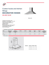
INSTALLATION INSTRUCTIONS:
The hood is supplied with all the necessary
accessories for installation. The minimum distance
between the cooker and the lower part of the hood
must be 750 mm for gas cookers and 650 mm for
electric cookers (Fig. 1). The hood is supplied with a
motor intake (Fig 2). If it has not been assembled by
the manufacturer, you can assemble it using the
supplied screws (for type 1) or pushing (for type 2)
If the motor intake is equipped with a non-return
valve, make sure it opens and closes perfectly.
The following instructions will assist installation:
a) The hood should be centred with respect to the
cooker.
The hood is supplied with two supports/hooks (a)
(Fig 3) or bracket (b) that need to be fixed to the
wall by means of wall anchors . The L1 holes for
these supports are on the back of the hood (fig.
4)
Remove the anti-grease filters, put the hood on
the wall and mark the position of the holes for the
supports/hooks.
d) Drill the two previously marked holes after
removing the hood from the wall.
e) Fix the two supports/hooks to the wall.
f) Mark the L2 holes on the wall to fix the hood
safely. (fig. 4) Drill and put the anchors in the
holes.
g) Hang the hood on to the supports/hooks (fig. 5)
and level by means of the adjusting screw
(fig.3).
h) Fix the hood safe by tightening both wall anchors.
Ducted mode or Recirculation mode installation:
Ducted mode:
In the ducted mode, connect the motor outlet to the
fumes outlet duct not less than 120mm diameter.
Warning: if the hood is equipped with an active
carbon filter, it must be removed (see page 7)
EN 02
Fig.2
Hood levelling screw
Fig.3
Type 1
Type 2
Fig.1
(a)
(b)