Page is loading ...

4009-9812 Class A Adapter
Option Card Installation Instructions
2000 Simplex Time Recorder Co., Westminster, MA 01441-0001 USA
All specifications and other information shown were current as of publication, and are subject to change without notice.
IDNet and TrueAlert are trademarks of Simplex Time Recorder Company.
Suffix “C” or “CA” following an eight-digit product ID number denotes ULC-listed product.
574-763
Rev. A
DO NOT INSTALL ANY SIMPLEX PRODUCT THAT APPEARS
DAMAGED. Upon unpacking your Simplex product, inspect the contents of
the carton for shipping damage. If damage is apparent, immediately file a claim
with the carrier and notify Simplex.
ELECTRICAL HAZARD - Disconnect electrical power when making any
internal adjustments or repairs. Servicing should be performed by qualified
Simplex Representatives.
STATIC HAZARD - Static electricity can damage components. Therefore,
handle as follows:
1. Ground yourself before opening or installing components (use the 553-484
Static Control Kit).
2. Keep uninstalled component wrapped in anti-static material at all times.
RADIO FREQUENCY ENERGY - This equipment can radiate radio
frequency energy and if not installed and used in accordance with the instruction
manual, may cause interference to radio communications. It has been tested and
found to comply with the limits for a Class A computing device pursuant to
Subpart J of Part 15 of FCC Rules, which are designed to provide reasonable
protection against such interference when operated in a commercial
environment. Operation of this equipment in a residential area may cause
interference in which case the user, at his own expense, will be required to take
whatever measures may be required to correct the interference.
This publication describes how to install the 4009-9812 Class A Adapter Option
Card into a 4009 TrueAlert Addressable Controller. The Class A Adapter card
provides the Addressable Controller with three Class A TrueAlert SLC circuits.
Refer to the TrueAlert Addressable Controller Installation Guide (574-762) for
configuration information. Refer to the 842-158 Field Wiring Diagram for
additional wiring information.
This publication discusses the following topics:
Topic See Page #
The Class A Adapter Option Card 2
Wiring 3
Mounting 4
Cautions and Warnings
Overview
In this Publication
firealarmresources.com

2
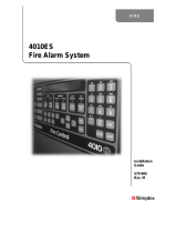
An aftermarket SLC option card is available to convert the three SLCs found on
the TrueAlert Addressable Controller system board to three Class A (Style 6)
hardwired SLCs. Each TrueAlert Addressable Controller supports one Class A
Adapter Option Card.
Figure 1 is an illustration of the Class A Adapter Option Card.
CLASS A CLASS A
4009T
TRIPLE-T
CLASS A
BD ASSY
565-992 B
CLASS A
Figure 1. 4009-9812 Class A Adapter Option Card
The Class A Adapter Option Card
Overview
firealarmresources.com

3
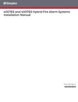
The Class A return wiring for system board SLC 1 is terminated at TB1 on the
Class A card. The other two SLCs must be terminated to complete the Style 6
loops (SLC2 to TB2 and SLC3 to TB3), regardless of whether or not those
circuits are used. Refer to the 842-158 Field Wiring Diagram for complete
wiring, compatible appliances, current, and line distance information.
Note: SLC wiring must be twisted pair (TWP).
Figure 2 is an illustration of the Class A Adapter Option Card wiring.
Figure 2. Class A Adapter Option Card Wiring
Wiring
Overview
SLC 1
Notes:
• All wiring must be 18AWG TWP
minimum (or to local code).
• All wiring is supervised and
power-limited.
4009-9812 CLASS A
ADAPTER OPTION CARD
(565-992)
firealarmresources.com

574-763
Rev. A
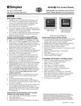
Install the 4009-9812 Class A Adapter Option Card piggy-backed onto the
Addressable Controller. Use the following steps and Figure 3 to mount the card.
1. Disconnect the battery and then AC power from the Addressable Controller.
2. Place one of the supplied insulating washers over the threaded end of each
of the three metal standoffs. Screw the three standoffs (Part No. 524-289)
into the threaded holes on the Addressable Controller system board.
3. Plug the two 6-pin headers (on the opposite side of P1 and P2 on the Class
A Adapter Option Card) into connectors P2 and P3 on the Addressable
Controller system board (see Figure 3). Check to verify the proper
alignment of P2 and P3.
4. Install screws (Part No. 440-008) to connect the Class A Adapter Option
Card to the three standoffs (see Figure 3). When you are done, reconnect
AC and battery power.
Figure 3. Class A Adapter Option Card Mounting
Mounting
Overview
HOLES FOR
524-289 STANDOFFS
P2, P3 6-PIN
CONNECTORS
firealarmresources.com
/