WaterWay 810-0067 User manual
- Category
- Above ground pool accessories
- Type
- User manual

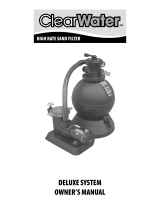
DELUXE SYSTEM
OWNER’S MANUAL
DE
CLEAR
WATER
TM

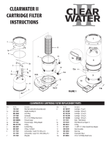
Our ClearWater II D.E. Filter System is shipped from Waterway complete
with everything you need right in the box. Assemble lter system only
after above-ground pool is installed. Fill pool with water. Do not raise
water level above pool return line.
The pool equipment should be located between pool skimmer and
return line. The ltration system should not be closer than 2 ft. and not
further than 5 ft. from the pool. The ClearWater II D.E. Filter System
needs to be on a completely at surface (e.g. patio block, cement slab,
etc.). The pump will require a 110 volt/20 amp service.
WARNING: A GFCI is required. Follow national and local
building and safety codes.
Before opening shipping carton, make sure box is in the upright
position. Inside the carton, you will nd:
1. One base
2. One pump (packaged in separate box)
3. One lter
4. Two lengths of 6 ft. hose
5. One bag with ttings
WARNING! READ ALL INSTRUCTIONS AND WARNING
LABELS BEFORE OPERATING FILTER!
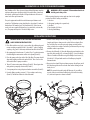
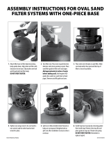
1. Place lter and base on a level, secure surface. Open ttings bag and
remove coupling assembly (Detail 2). Assemble 2" gasket, coupling,
coupling o-ring, and 2" union nut, and thread into inlet side of lter.
2. Open pump trap lid and remove 2" gasket. Place 2" gasket into union
nut. Hand tighten union nut to suction side of pump (Detail 2).
3. Place the pump on the base to the left of the lter. The pump should
align with coupling on lter side marked “Inlet”. There is no need to
disassemble lter or pump assemblies.
4. Thread 2" union nut to pump discharge (Detail 2). Thread gate valve
with gasket to pump trap suction side (Detail 2).
5. Secure pump to base using the pin and anchor assemblies (Detail 1).
6. From the ttings package, remove 1 ½" hose adapter and o-ring
(Detail 2). Thread into outlet side of the lter tank.
7. Remove 4 hose clamps from the ttings bag. Select one of the hose
lengths and slip one clamp over the end of the hose adapter. Place
the end of the hose on to the gate valve (pump suction) and the
other end to the hose adapter end of the pool skimmer. Repeat steps
with lter outlet to pool return.
8. Remove the lid handle, #1, from the ttings bag and attach it to the
top of the lid assembly, #12, as shown (Detail 3). Secure ClearWater
Filter to ClearWater Filter Base using #26a Phillips-head screws (2),
(Detail 4 & 5). Fill pool until water level is halfway up length of
skimmer throat.
9. Open air release knob. Plug in and turn on pump. Air will pass out of
the lter through the air release knob. Once water discharges from
knob, close it.
NOTE: To remove lid assembly, take o lter nut, #3, insert lter
wrench, #20a, in notch between lter body, #20 and lid assembly,
#12, twist and separate as shown in Detail 5.
CLEARWATER II D.E. FILTER SYSTEM OWNER’S MANUAL
INSTALLATION INSTRUCTIONS
30
31
DETAIL 1 DETAIL 2
21
21
29
25
27
28
22
24
23
29
39
23
24

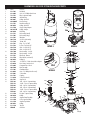
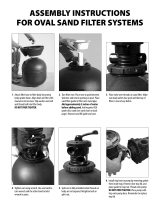
CLEARWATER II D.E FILTER SYSTEM REPLACEMENT PARTS
Item Part No. Description
1 519-7601 Lid Handle
2 819-9002 #12 x ¾" S/S Phillips Head Screw
3 718-7251 Filter Locknut Assembly
4 602-0200 Air Relief Plug
5 805-0207 O-Ring - Air Relief
6 830-4000SS Pressure Gauge
7 519-7451 Handle Assembly (2)
8 805-0224 O-Ring - Air Relief
9 519-7430 Gauge - Fitting Adapter
10 805-0117SD O-Ring - Adapter
11 805-0460 Lid O-Ring
12 519-7411 Lid Assembly (small)
519-7401 Lid Assembly (large)
13 519-7441 Wing-Nut
14 500-7310 Screen/Sock Assembly
15 718-7210 Tie Nut - D.E.
16 419-7241 Plug - 2" x 1 ½" MPT
17 519-7269 Locator - Top Grids - D.E.
18 550-7210 Grids - 12 sq. ft. D.E. (7)
550-7220 Grids - 18 sq. ft. D.E. (7)
19 550-7100 Base Assembly - 12 sq. ft.
550-7120 Base Assembly - 18 sq. ft.
20 515-7251 Filter Body - Bottom
20a 519-7470 Filter Wrench (see Detail 5)
21 805-0224 O-Ring (3)
22 417-6241 1 ½" MPT x 1 ½" Male Smooth Hose Adapter
23 872-0010 Hose Clamp - Stainless Steel
24 872-9002 Corrugated Hose - Black
25 500-5300 Drain Assembly
26 672-7401 ClearWater II Base
26a 819-0044 #10 x 1" S/S Phillips Head Screw (2)
27 415-5001 2" Union Nut
28 419-7241 Coupling
29 711-4010 2" Union Gasket (2)
30 429-7221 Snap Pin (4)
31 PSP1100 1 HP - 1-Speed - Supreme Pump
PSP1150 1 ½ HP - 1-Speed - Supreme Pump
PSP1200 2 HP - 1-Speed - Supreme Pump
PSP2100 1 HP - 2-Speed - Supreme Pump
PSP2150 1 ½ HP - 2-Speed - Supreme Pump
PSP2200 2 HP - 2-Speed - Supreme Pump
32 311-1520 Faceplate - Supreme Pump
33 805-0330 O-Ring
34 319-1510 Supreme Pump Trap Body
35 319-1540 C-Clip - Supreme Pump
36 319-1530 Supreme Trap Basket
37 805-0439 O-Ring
38 511-1310 Trap Lid
39 WV001H Gate Valve
DETAIL 4
3
12
20
20a
26a
26a
1
6
7
89
2
3
4
5
10
12
14
16
7
11
13
15
17
18
20
19
21 22 24
23
25
26
31
30
32
33
34
29
23
24 36
37
38
35
29 28
21
27
39
30
21
26a (2)
DETAIL 5
26a
DETAIL 3
1
2

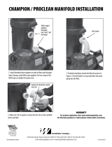
If the pressure gauge on your lter reads 5 PSI or higher than the
original starting pressure, the lter needs to be cleaned. The ClearWater
II D.E. Filter System features the exclusive 1-2-3 Safety Locking System
to ensure safe and simple lter maintenance.
1. Turn o pump. WARNING: Never attempt to clean lter while
pump is running. This is a pressurized vessel. It could cause
severe injury or harm to your person. Plug skimmer and pool
return lines or drain pool water level to below pool return line.
2. Slowly open the air release knob on top of lter until the pressure
gauge reads “0”. Open drain cap at bottom of lter and allow water
to ow.
3. Press the yellow safety latch on the underside of the locking nut and
turn the nut counterclockwise to remove the lid. Rinse the D.E. grids
with a garden hose. There is no need to remove the element from the
lter.
4. Reassemble lid and follow start-up procedures from original
instructions.
My Original Starting Pressure is ________ PSI (Pounds per
Square Inch). I should clean the lter at ________ PSI.
CLEANING INSTRUCTIONS
WARRANTY
For product registration visit: www.waterwayplastics.com.
For Warranty questions or claims please contact point of purchase.
810-0067.0323
©2023 Waterway Plastics
2200 East Sturgis Road, Oxnard CA 93030 • Phone 805.981.0262 • Fax 805.981.9403
www.waterwayplastics.com • waterway@waterwayplastics.com
Designed,
Engineered &
Manufactured
in the USA.
-
 1
1
-
 2
2
-
 3
3
-
 4
4


WaterWay 810-0067 User manual
- Category
- Above ground pool accessories
- Type
- User manual
Ask a question and I''ll find the answer in the document
Finding information in a document is now easier with AI
Related papers
-
 WaterWay 810-0074-HP User manual
-
WaterWay 522-5147-6S Owner's manual
-
 WaterWay 810-0176 User manual
-
 WaterWay 810-0064-C User manual
-
 WaterWay 810-0164 User manual
-
 WaterWay 810-0168 User manual
-
 WaterWay 810-0190 User manual
-
 WaterWay 810-0081 User manual
-
 WaterWay 810-0082-2 User manual
-
 WaterWay 810-0082-N2 User manual


Other documents
-
Pentair FullFloXF User guide
-
-
Pentair FNS Plus User guide
-
Pentair EC-180009 Installation guide
-
Pentair D.E. Cartridge Style Filter User manual
-
Pentair Swimming Pool Filter Quad D.E. User manual
-
-
-
Hayward W3EC50C93S Owner's manual
-